
Abstract
A multi-objective optimal model of a K-H-V cycloid pin gear planetary reducer is presented in this article. The optimal model is established by taking the objective functions of the reducer volume, the force of the turning arm bearing, and the maximum bending stress of the pin. The optimization aims to decrease these objectives and obtains a set of Pareto optimal solutions. In order to improve the spread of the Pareto front, the density estimation metric (crowding distance) of non-dominated sorting genetic algorithm II is replaced by the k nearest neighbor distance. Then, the improved algorithm is used to solve this optimal model. The results indicate that the modified algorithm can obtain the better Pareto optimal solutions than the solution by the routine design.
Keywords
Introduction
Cycloid speed reducers have some excellent characteristics, such as compact structure, wide scope of ratios, high transmission efficiency, low noise, and smoothness. Thus, they are widely used in all kinds of mechanical transmission. However, many design parameters and complex constraints in the reducer design bring more difficulty. At present, a lot of researches are available in this area. Chen et al. 1 established the equation of meshing for small teeth difference planetary gearing and a universal equation of cycloid gear tooth profile based on cylindrical pin tooth and given motion. He et al. 2 carried out optimum design and experiment on the double crank ring-plate-type pin-cycloid planetary drive to reduce its noise and vibration. Sensinger 3 presented a unified design method to optimize cycloidal drive profile, efficiency, and stress. Blagojevic et al. 4 introduced a new two-stage cycloid speed reducer, which was characterized by good load distribution and dynamic balance. Blagojevic et al. 5 found the friction between cycloid disk and housing rollers affected the contact force, friction torque, and transmission efficiency. Hsieh 6 proved the nonpinwheel design of cycloid speed reducer could effectively reduce vibration, stress value, and stress fluctuation.
In the engineering design, many multi-objective optimization problems (MOOPs) can be found. Some or all objectives often conflict with each other; in other words, all objectives cannot achieve its own best value simultaneously. 7 Thus, the policymakers need to choose the compromise design parameters according to the reality. For the last decade and more, many classical multi-objective evolutionary algorithms (MOEAs) were studied, such as the non-dominated sorting genetic algorithm II (NSGA-II), 8 the improved strength Pareto evolutionary algorithm (SPEA2), 9 and the multi-objective particle swarm optimization (MOPSO). 10 As an efficient algorithm, NSGA-II has been widely used to solve MOOPs.11–13 Some researchers used NSGA-II to optimize gear reducers. Deb and Jain 14 proved MOEAs can solve multi-speed gearbox design optimization problem with more than one optimal goal and different kinds of design parameters. Tripathi and Chauhan 15 applied NSGA-II to optimize the volume of gearbox and the surface fatigue life factor simultaneously. Sanghvi et al. 16 used NSGA-II to solve optimization design problem of a two-stage helical gear train, in which the bearing force and volume were optimized. Three optimization methods (MATLAB optimum tools, genetic algorithm, and NSGA-II) were compared. It was shown that NSGA-II obtained better optimization objective values than other methods. Li et al. 17 combined NSGA-II and fuzzy set theory to optimize dynamic model of steering mechanism and got the better result than the original design. However, far too little attention has been paid to the research about multi-objective optimal design of cycloid speed reducers. Yu et al. 18 and Yu and Xu 19 selected volume as the optimization objective. Xi et al. 20 selected volume and efficiency as optimization objectives, and the multi-objective optimization model was solved by transforming it into a single-objective problem, which ignored the relationship between objectives. Wang et al. 21 focused on reducing the volume and improving the efficiency of reducers, and the optimal model was solved by the MATLAB genetic algorithm toolbox.
In this article, a multi-objective optimization model of reducer is established to minimize the volume of the reducer, force of the turning arm bearing, and maximal bending stress of the pin. It is expected to provide a new way for multi-objective optimization design of cycloid reducer and similar structural optimization problems. Moreover, in order to improve the spread of the Pareto front, the density estimation metric of NSGA-II is replaced by the k nearest neighbor distance.
Optimization design model of the K-H-V cycloid driver
Figure 1 shows the typical structure of the cycloidal pinwheel transmission, which mainly consists of the following parts:
Planet carrier. It is composed of two parts, namely, the input shaft and the dual eccentric sleeves.
Pin gear (also called pinwheel). It is uniformly distributed over the circumferential direction. The pin gear consists of the pin and pin sleeve.
Cycloid gear. To keep the static balance of the input shaft and increase the loading capacity of the reducer, two identical cycloid gear structures are usually adopted. The cycloid gears are installed on the dual eccentric sleeves, and their position differs 180°. In order to reduce the friction between eccentric sleeve and cycloid gear, the turning arm bearing is installed between the two parts.
Output mechanism. This reducer often uses the output mechanism that called pin axle type. There are some cylindrical pin holes on the cycloid gear for inserting the cylindrical pins (the cylindrical pin sleeve is mounted on the cylindrical pin). Thus, the rotation motion of cycloid gears can be output by cylindrical pins.

Typical structure of cycloidal pinwheel transmission.
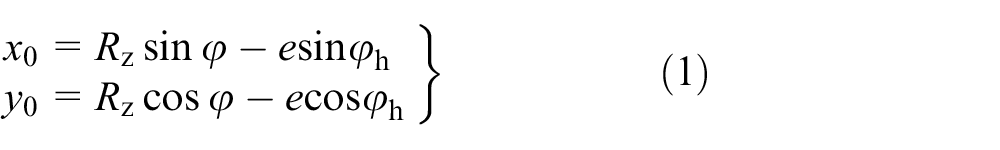
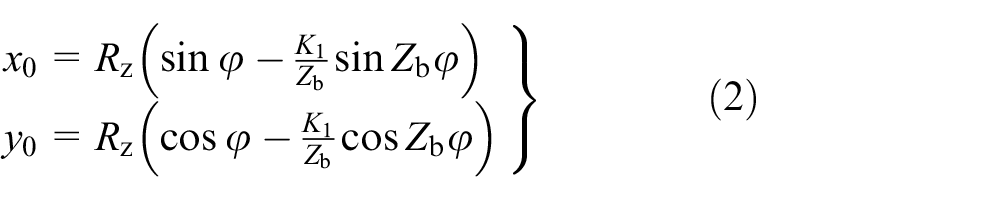
Theoretical tooth profile of cycloid gear
As shown in Figure 2, rolling circle 2 is the circumscribed circle of base circle 1, and the center of base circle 1
where

Theoretical tooth profile of cycloid gear.
According to the radius of curvature formula, the radius of theoretical tooth profile of cycloid gear can be expressed as

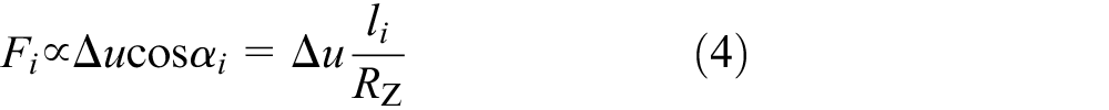
Meshing force of pin gear and cycloid gear
As shown in Figure 3, the angular velocity
where
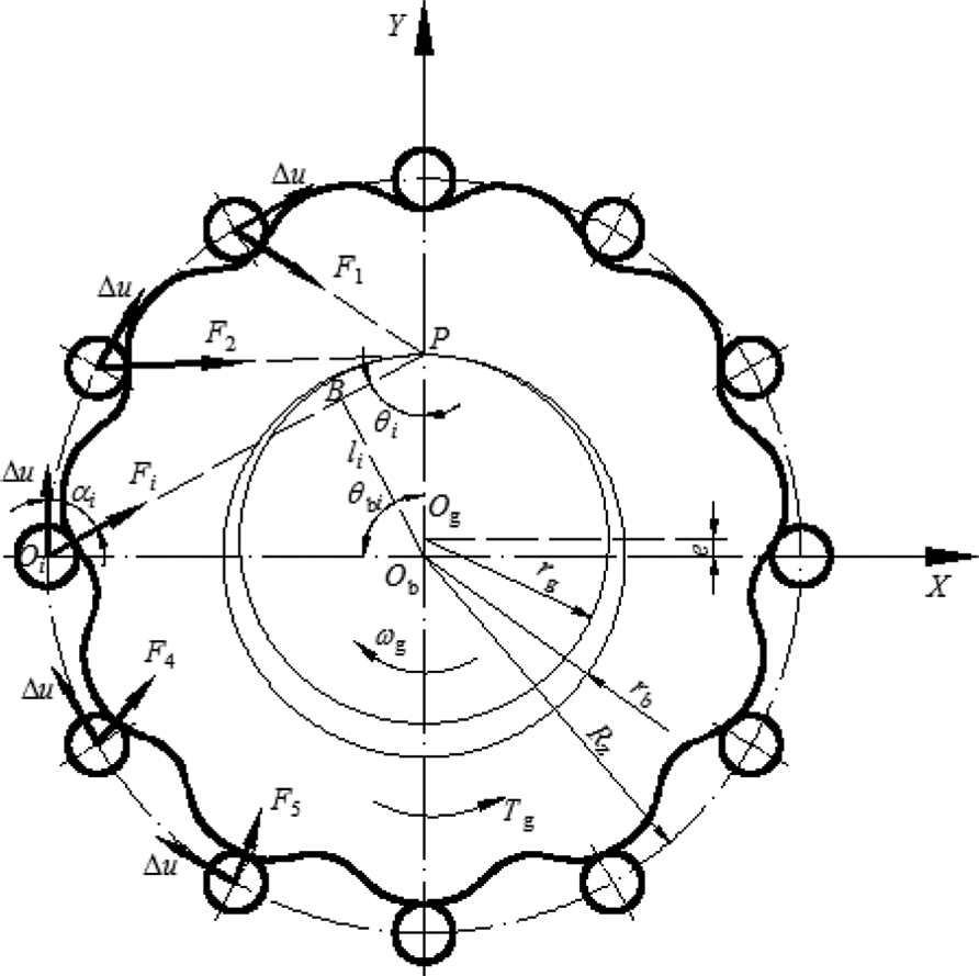
Meshing force of pin gear and cycloid gear.
In the triangle ObBP,

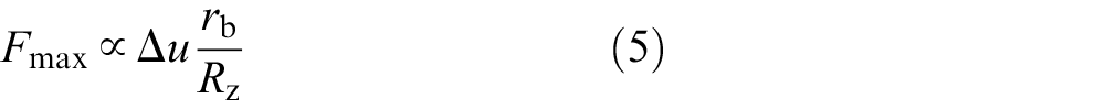
The maximum engaging force 22 is shown as
where
In the triangle PObOi, according to sine theorem,

Besides, according to cosine theorem,

Because
According to equations (6), (8), (9), and (11),

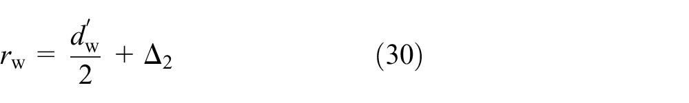
Design variables
A vector which consists of five design variables is expressed as
Objective functions
For the convenience, the input power, input speed, transmission ratio, turning arm bearing, and the number of cylindrical pins are given. Under these premises, the sub-objectives are presented as follows.
Volume of reducer
The radial dimension is affected by the diameter of the pin gear distributed circle
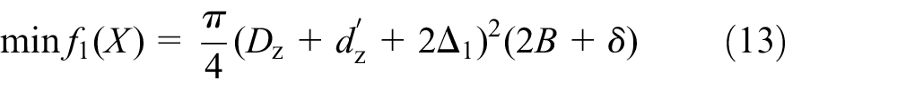
where
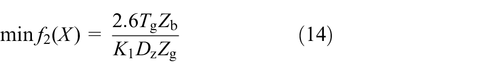
Radial load on turning arm bearing
The service life of turning arm bearing largely depends on its radial load. It further affects the service life of the speed reducer. Hence, minimizing the radial load of the turning arm bearing should be considered. It can be expressed as
Maximal bending stress of the pin
The break in pin is one of the main failure forms of this cycloid reducer. Hence, minimizing the maximal bending stress of the pin is the third sub-objection. For pin gear which has two fulcrums (in Figure 4), the bending stress of the pin is shown as follows

where


Typical structure of a pin gear with two pivots.
Constraint conditions
Short amplitude coefficient
If the short amplitude coefficient is bigger, the minimal radius of theoretical tooth profile of cycloid gear will be reduced, which will decrease the outer radius of the pin sleeve, that is, the contact strength of the cycloid gear and the pin gear increases. According to equation (16), the bending stress of the pin will increase with the decrease in the short amplitude coefficient. It suggests that the constraint range of the short amplitude coefficient is [0.45, 0.8]; 20 thus, the constraint equation can be defined by

Cycloid tooth profile
To prevent cycloid tooth profile from undercut and sharp angle, the ratio of an external diameter of the pin sleeve to a diameter of the pin gear distributed circle should be less than the minimum coefficient of the theoretical tooth profile curvature radius

where
Maximum diameter of the cylindrical pin hole
In order to guarantee the strength of the cycloid gear, there must be a certain thickness


where

where

where
Pin-diameter coefficient
In order to guarantee the strength of the pin gear housing and avoid the interface of pin gears, the value of pin-diameter coefficient


where
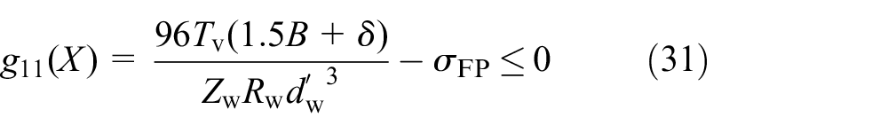
Contact strength of the cycloid gear and the pin gear
To prevent the tooth surface from scuffing failure and fatigue pitting, the meshing between the pin teeth and the cycloidal gear teeth should meet the contact strength. Using Hertz theory, the contact stress

where
where
Bending strength of the pin gear
According to equation (15), the constraint is as follows

where
Contact strength between the cylindrical pin and the cylindrical pin hole
According to Rao, 22 this constraint is as follows

where
where
Bending strength of the cylindrical pin
According to Rao, 22 this constraint can be expressed as
Life of the turning arm bearing

where
Improved NSGA-II (NSGAN)
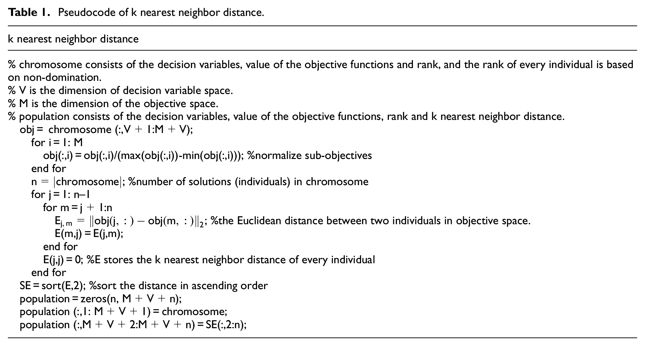
Non-dominated ranking and crowding distance are adopted in NSGA-II to control the evolutionary population size. The density estimation technique of the crowding distance calculates the average distance of two points on either side of this point along each of the objectives. Sometimes, this method cannot completely reflect the crowdedness between individuals. As shown in Figure 5, supposing that d represents the unit of a distance in objective space, the distance of solution A (12d) is equal to that of the solution B (12d) according to crowding distance. And, it can also be seen that B is more crowded than A. However, the density estimation metric of the k nearest neighbor distance
9
can avoid this case. Through the k nearest neighbor distance, the first nearest neighbor distance of B
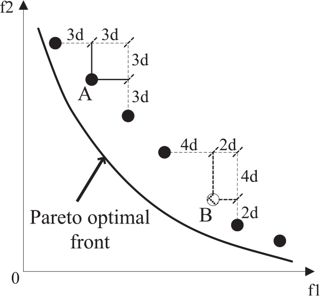
Pareto front.
Pseudocode of k nearest neighbor distance.
Optimization design example
GCr15 material is selected for pin, pin sleeve, cycloid gear, cylindrical pin, and cylindrical pin sleeve. The main model parameters 22 are shown in Table 2.
Model parameters.

NSGA-II and NSGAN are adopted to optimize this model, respectively. The parameters in algorithms are listed as following: population size N is 100, evolutional generation is 600, crossover probability pc is 0.9, and mutation probability pm is 1/n, where “n” represents the number of the design variables. The two algorithms run 30 times independently. According to Table 2 and Rao, 22 the range of design variables is shown in Table 3.
Range of design variables.

The optimization procedure is shown in Figure 6. At first, an initial population is randomly created in the range of design variables, and the solutions utilize real-number encoding. Second, compute the rank and k nearest neighbor distance for the every individual in population. Then, the binary tournament selection, recombination, and mutation operators are used to create an offspring population. In a binary tournament selection, a lower rank and bigger k nearest neighbor distance is the selection criteria. NSGAN uses simulated binary crossover and polynomial mutation. After that, the next population is selected from the offspring and previously population based on the rank and k nearest neighbor distance. If the maximal generation is reached, output the result; if not, keep on evolving.

Flowchart of optimization procedure based on NSGAN.
Spread test
There are three sub-objectives, and the spread indicator 23 is chosen to measure the spread of the Pareto front corresponding to obtained solutions. The smaller this value is, the more uniform the solutions distribute. The indicator is defined as

where


Three extreme solutions (i.e. these solutions have a maximal sub-objective value) are selected among the obtained solutions based on the two algorithms. Their objective values are shown as follows: E1 (3.11e–3, 4746.33, 34.44), E2 (1.49e–3, 10756.94, 94.89), and E3 (1.43e–3, 8444.82, 150.00). Among them, E1 and E2 come from NSGAN, and E3 comes from NSGA-II. Compute the spread indicators of the Pareto front obtained by two algorithms. The Pareto fronts obtained by the two algorithms are shown in Figures 7 and 8. Spread indicator statistical result is shown in Table 4.

Pareto front obtained by NSGA-II.
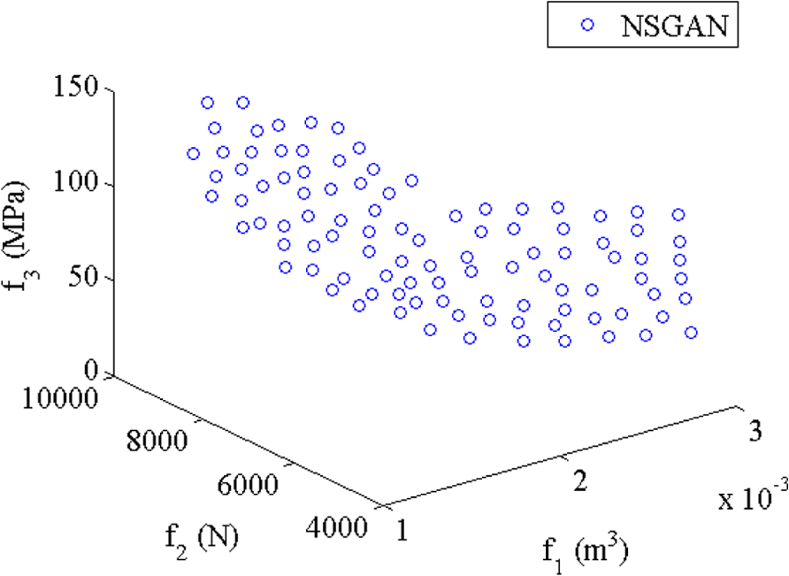
Pareto front obtained by NSGAN.
Average and standard deviation of the spread indicator.

From Figures 7 and 8, it can be shown that the NSGAN gets a more uniform Pareto front than that by NSGA-II. Table 3 shows a statistical result of the spread indicator. These data demonstrate that NSGAN obtains better result than NSGA-II in terms of the spread. In order to prove NSGAN has a significant role in the spread, a t-test is performed for the average of the spread indicator by software SPSS. The significance level is supposed as 0.05. The t statistic is 53.513, and the corresponding two-tailed probability is 0.000. Because the two-tailed probability is smaller than the significance level, the null hypothesis is refused. It shows that two algorithms have significant differences in spread indicator.
Results analysis
A total of 100 non-dominated solutions are picked out from 3000 solutions gained by NSGAN according to rank and k nearest neighbor distance. The minimal sub-objective solutions (volume, radial load of the turning arm bearing, or maximal bending strength of the pin) are selected out from 100 non-dominated solutions. These solutions are Solution 1 (1.37e–3, 9188.71, 149.93), Solution 2 (2.92e–3, 4741.87, 40.96), and Solution3 (2.82e–3, 4853.17, 33.50). From three extreme solutions, three sub-objectives cannot reach minimum together. Figure 8 presents the Pareto front of 100 non-dominated solutions. In addition, the sub-objectives of the routine design 22 are also shown in Figure 9.
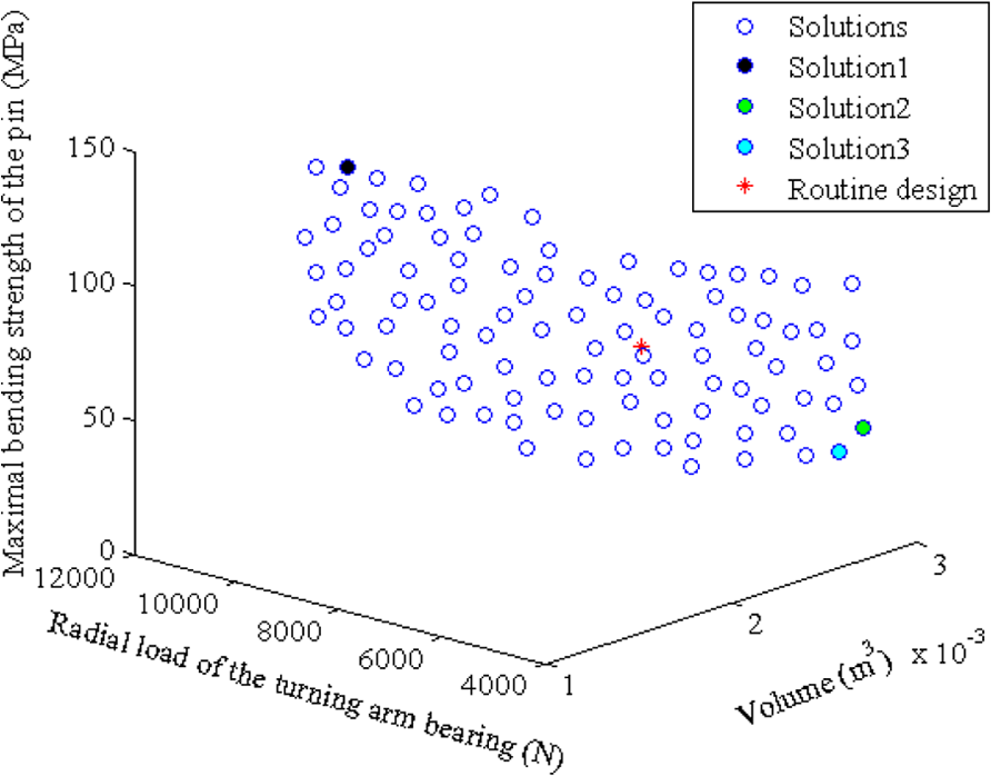
Non-dominated Pareto front obtained by NSGAN.
Next, the solutions for which the three sub-objectives are all smaller than that of the routine design are picked out from Figure 9, which are shown in Figure 10. There are eight total solutions whose three sub-objectives are smaller than that of the routine design. Table 5 presents the design variables and sub-objectives of these eight solutions and the routine design. Besides, the design variables are rounded under the premise of meeting the constraints.

Three sub-objectives are smaller than that of the routine design.
Design variables and sub-objectives.

Through the above analysis, NSGAN can obtain solutions for which the three sub-objectives are superior to that of the routine design. However, in the practical design, due to some sub-objectives conflict with each other, the designer has to make a compromise. For example, the designers can minimize the volume of the reducer and maximal bending stress of the pin, but appropriately increase the radial load of the turning arm bearing under the constraints, i.e., make a compromise. Depending on this situation, some preference solutions are selected from the 100 non-dominated solutions. For the better comparison, Figure 11 shows the relationship between volume and radial load of the turning arm bearing, and Figure 12 illustrates the relationship between volume and maximal bending stress of the pin. When the volume increases, the radial load of the turning arm bearing will be reduced. Moreover, according to equations (14) and (15), the f1 (volume) and f2 (radial load of the turning arm bearing) are conflicting. The increase of volume can reduce the maximum bending stress of the pin to a certain extent. However, the maximum bending stress of the pin is not entirely dependent on volume, and equation (16) shows that short amplitude coefficient can also have impact on maximal bending stress of the pin.

Volume of the reducer and radial load of the turning arm bearing.

Volume of the reducer and maximal bending strength of the pin.
In Figures 11 and 12, there are five magenta preference solutions. As shown in Figure 11, the second sub-objective (radial load on bearing) is bigger than that of the routine design, but the first sub-objective (volume) is smaller than that of the routine design. Meanwhile, the third sub-objective (maximal bending strength of the pin) is also smaller than that of the routine design according to Figure 12. These five preference solutions sacrifice the second sub-objective, but the first sub-objective is obviously improved.
Conclusion
A multi-objective optimization model of a cycloid pin gear planetary reducer with the goals of minimizing the volume, the radial load on turning arm bearing, and the maximal bending stress of the pin is considered in this article. The density estimation technique of NSGA-II is improved using the k nearest neighbor distance. The improved algorithm (NSGAN) is used to solve the multi-objective optimization design model. Although some sub-objectives conflict with each other, the MOEA can optimize these sub-objectives simultaneously. NSGAN obtains more uniform Pareto fronts than NSGA-II, and the Pareto front can present the relationship between sub-objectives, which is more convenient for the designers to select design solutions.
Footnotes
Academic Editor: Ismet Baran
Declaration of conflicting interests
The author(s) declared no potential conflicts of interest with respect to the research, authorship, and/or publication of this article.
Funding
The author(s) disclosed receipt of the following financial support for the research, authorship, and/or publication of this article: This work was supported, in part, by a grant from Natural Science Foundation of Zhejiang Province of China (Nos LY16G010013, LY17E050023, and LQ16E050012), National High-Tech R&D Program of China (No. 2015AA043002), and National Natural Science Foundation of China (No. 71371170).