
Abstract
The numbers of long-distance transport pipelines constructed in areas with relatively complex terrain and large topographic changes have increased in recent years. A water hammer can occur easily during operational processes, such as the starting and stopping of a pump station, the adjustment of the speed of a pump unit, and a shutdown due to an incident and failure of a regulating valve. These operations may cause fluid column separation and form a dangerous water hammer due to the collapse of air cavities. Water hammers due to the collapse of air cavities are a complicated two-phase (gas–liquid) fluid mechanics problem. This study carries out a theoretical study and a numerical simulation of water hammers that occur due to the collapse of flow interruption–caused air cavities and their prevention. This study establishes and solves a discrete model for air cavities caused by flow interruptions and develops a program to numerically simulate water hammers that occur due to the collapse of these air cavities. In addition, based on an actual pipeline incident in which the stopping of a pump resulted in water hammers at multiple locations due to the collapse of air cavities from fluid column separation, numerical simulations are used to plot the lowest and highest hydraulic head envelope curves and the transient curves of the water hammer at the major points, analyze the transient process of the pipeline system, and propose a preventive measure that can effectively control the water hammer pressure and reduce the occurrence of incidents.
Keywords
Introduction
Numerous researchers have performed extensive studies on the two-phase (gas–liquid) transient process that results from water hammers due to the collapse of flow interruption–caused air cavities and have examined the effect of gas release on the transient process of liquid column separation. 1
By calculating and measuring water hammer data from two water transport pipelines, Brown found that the dissolved gas in the water should not be neglected during the analysis of water hammers and showed that the higher the gas content, the higher the reverse rotation speed of the pump and the water hammer surge head during the water hammer process. 2 Through extensive experimentation, Wylie and Streeter et al. concluded that the gas released during a liquid column separation process would decrease the propagation speed of the water hammer wave and cause it to weaken rapidly.3–5 Based on a summary of previous research results, Kalkwijk and Kranenburg 6 proposed two methods to improve the accuracy of calculation results. One method is to correct the wave speed; the speed of a wave is considered to remain at its initial speed when the pressure is greater than the saturated vapor pressure, whereas the speed of a wave is considered to change constantly due to gas release when the pressure is less than the saturated vapor pressure. The other correction method is to divide the water hammer model into a cavity-free area, a cavity area and a transient area and develop a mathematical model for each area. 7
Researchers have mathematically described liquid column separation processes mainly using the separated flow model and the concentrated cavity model. 8 The separated flow model classifies pipeline flow during a water hammer process into a full flow and a nonfull flow based on whether the pipeline is completely filled with liquid. The concentrated cavity model treats a cavity caused by flow interruption due to liquid column separation as a cavity that is fixed at a certain preset cross section of the pipeline. In total, three methods can be used to treat this model: (1) When the cavity caused by flow interruption is a vapor cavity, only the vaporization of the liquid when the pressure decreases to below the saturated vapor pressure is considered, whereas the effect of the release of the dissolved gas in the liquid during the liquid column separation process on the water hammer process is not considered; in addition, the cavity is assumed to be filled only with vapor. Vapor cavitation is two-phase one component flow. (2) When the cavity is a mixed cavity, based on the treatment method for vapor cavities, the effect of the dissolved gas in the liquid on the transient water hammer process during propagation of the decompression wave is further considered. This method is suitable for water hammers that occur in long-distance transport pipelines because the gas release process in these pipelines is very slow, and the water hammer process in these pipelines is relatively long; thus, the dissolved gas in the liquid has sufficient time to escape. Gas cavitation is two-phase two-component flow. (3) Based on the treatment method for mixed cavities, the areas surrounding the two boundaries of a cavity caused by flow interruption are treated as transient areas; that is, the small bubbles of vapor and dissolved gas are evenly distributed in the liquid. This treatment method is most consistent with the actual conditions in operating pipelines. 9
Researchers have developed different mathematical models to describe liquid column separation processes.10,11 However, all of the calculation results differ from measured values because several unknown factors about the liquid column separation phenomenon still need to be investigated. Thus, there is still a lack of a universally accepted method for analyzing the liquid column separation phenomenon that occurs inside pipelines.
Theory and method
The pressure in some parts of a pipeline will decrease when the pipeline is affected by the decompression wave of a water hammer, which results in the escape of dissolved gas and the vaporization of the liquid. The bubbles then coalesce with the vapor to form large gas pockets that flow with the liquid. The gas pockets tend to stop and aggregate at the high points or sections of the pipeline and form relatively large bubble areas. After a bubble area forms, it will continuously grow until the pressures of the liquid columns on both sides of the bubble area reach equilibrium; 12 the bubble area may then occupy a very long section of the pipeline or even separate the liquid and block the entire cross section of the pipeline, which disrupts the continuity of the liquid and forms a complete flow interruption–caused cavity. This phenomenon is referred to as liquid column separation.13,14
During a water hammer process that occurs due to the collapse of flow interruption–caused air cavities, the curve that connects the minimum hydraulic head at each point on the pipeline is referred to as the minimum hydraulic head envelope curve. The minimum hydraulic head at each point does not occur at the same time. The curve that connects the critical hydraulic head value at each point on the pipeline at which liquid column separation occurs is referred to as the critical liquid column separation curve; it is determined based on the different boundary conditions on the pipeline and can be obtained through calculations based on the actual working conditions. According to the position relationship between minimum hydraulic head envelope curve and the critical liquid column separation curve can determine whether the liquid column separation will occur and the time and location of the occurrence.15,16
When the minimum hydraulic head envelope curve is higher than the critical liquid column separation curve (i.e. the two curves are neither tangent to each other nor do they intersect), liquid column separation will not occur along the pipeline. When the minimum hydraulic head envelope curve is lower than the critical liquid column separation curve, liquid column separation will occur in the pipeline.
To prevent the occurrence of liquid column separation and water hammers due to the collapse of flow interruption–caused air cavities and prevent damage to the pumps and pipeline system, it is necessary to implement effective, reasonable preventive measures.
Water hammer equation and its solution method
The equation of motion and the continuity equation for the changes in the flow rate and pressure head in the process of water hammer due to the collapse of air cavities are generally solved using the method of characteristics, which were adequately proved by Wylie and Streeter 4 in 1993


It is complex to determine the viscous force in the process of pipeline transient flow. In order to simplify the analysis, it assumes that the friction coefficient f remains constant in the transient flow (be equal to the value of the steady flow). Staggered grid of the method of characteristics and second-order numerical solution for frictional term could conform with the engineering practice better.
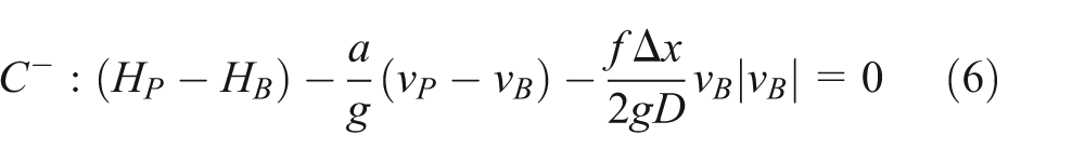
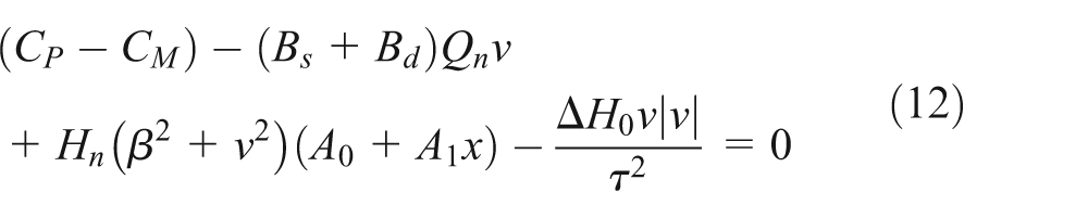
These two equations are a system of quasi-linear hyperbolic curve-type partial differential equations that can be transformed to systems of equivalent ordinary differential equations, which are expressed using
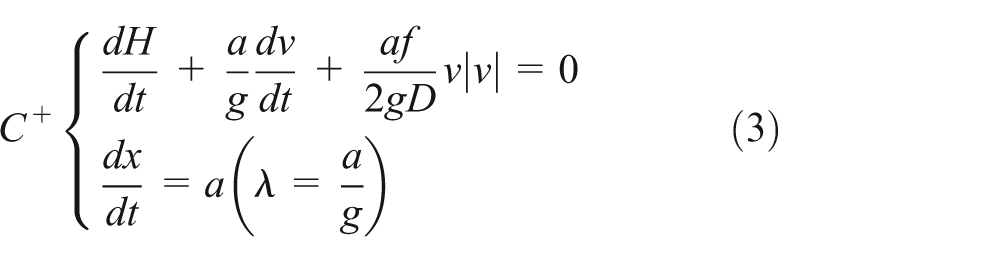

Equations (3) and (4) are collectively referred to as the characteristic system of equations of water hammers.
The model is solved using the finite difference method.
18
The entire pipeline is divided into N sections, each of which has a length of

Method of characteristics and its finite element solution method.
Therefore, the finite difference equations of equations (3) and (4) are

Let


Establishment and solution of boundary conditions
Boundary condition for a tank with a constant liquid level
An upstream liquid tank with a sufficiently large capacity is assumed to be a pump with a constant liquid level during a short-duration water hammer process:

The end of an oil pipeline is often connected to an oil tank. A pressure-regulating valve is sometimes placed on an oil pipeline before the oil tank to control the inlet pressure. The oil tank at the end of a pipeline can be treated as a tank with a constant liquid level. The boundary condition for a downstream tank with a constant liquid level is
where
Boundary condition for a centrifugal pump and the shutdown of a pump due to an incident
We set the inlet pressure of the pump station

where
Figure 2 shows the boundary condition for a centrifugal pump with a check valve installed at the outlet after it is shut down due to an incident.
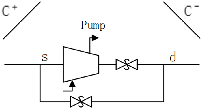
Boundary condition for a centrifugal pump.
Based on the principles of mass conservation and equilibrium between the upstream and downstream pressures of a deceleration pump, the pressure head equilibrium equation for a deceleration pump can be obtained
where
When a pump is shut down due to an incident, the active moment of the motor becomes 0, and the counter moment of the fluid exerted on the impeller (

where
The state parameters of the centrifugal pump,
Boundary condition for a two-stage slow-closing butterfly valve
The hydraulic head equilibrium equation (equation (14)) and the characteristic equation for deceleration (equation (15)) that corresponds to the two-stage slow closure of the butterfly valve at the outlet of a pump during a water hammer process caused by the shutdown of the pump due to an incident can also be established


where
Similar to the method used to solve the boundary condition for a centrifugal pump, the Newton–Raphson method is also used to solve the boundary condition for a two-stage slow-closing butterfly valve, but
A two-stage slow-closing butterfly valve is also installed at point


By simultaneously solving these two equations, we obtain
Development and solution of a discrete model for air cavities caused by complete flow interruption
In engineering practice, air valves are installed at points along a pipeline, such as humps, knees and peaks, to prevent negative pressure. When the pressure at a location in a pipeline decreases to below atmospheric pressure and liquid column separation begins to occur due to the effect of a water hammer wave, air is automatically injected via the air valves until the flow rates of the liquid columns on both sides of the air cavity are the same. At this time, the cavity is completely filled with air, and the pressure in the cavity is equal to atmospheric pressure.
Figure 3 shows the discrete model for air cavities caused by complete flow interruption, in which an air valve is assumed to be installed at cross section

Schematic diagram of the discrete mathematical model for air cavities caused by complete flow interruption.
The compatibility equations for cross section


When the pipeline is completely filled with a liquid or the pressure inside the pipeline is greater than atmospheric pressure (i.e. when the valves are closed),
When the hydraulic head of the piezometric tube at
The change in the air inside the pipeline is assumed to satisfy the isotherm law

where
The relationship between the absolute pressure inside the pipeline at cross section
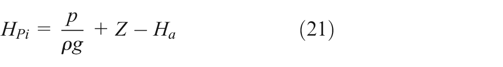
where
During the water hammer calculation process, the volume of air at

where
The mass of the air inside the pipeline is
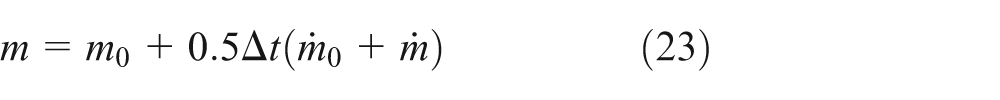
where
Substituting compatibility equations (22) and (23) into equation (20) results in
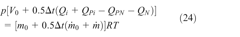

By substituting equations (18) and (19) into equation (24), we have

where
The heat exchange between the air and the pipe wall and liquid when the air enters and leaves the air valve is assumed to be negligible. The mass flow of air that passes through the cross section of the nozzle is 20

The pressure and rate of the airflow that passes through the cross section of the nozzle are defined as the critical pressure (

where
By substituting equation (26) into equation (27), the mass flow of air that passes through the nozzle in the critical state is obtained

This equation is used to calculate the mass flow of air that passes through the nozzle. For the air that enters and leaves the air valve, the atmospheric pressure state is its stagnation state, and atmospheric pressure is its stagnation pressure, that is,
The valve action is selected based on the actual engineering conditions. By selecting a proper boundary condition and substituting it into equation (25), the quadratic equation of the absolute pressure inside the pipeline (
Development of a calculation program for water hammers due to the collapse of air cavities caused by flow interruption and their prevention
The development of a calculation program for water hammers that occur due to the collapse of air cavities caused by flow interruption should be based on simple pipelines. By altering and adding different boundary conditions and selecting different mathematical models for the water hammers based on the actual working conditions, a calculation program can then be developed for complex pipelines. Algorithm 1 is the complete algorithm for the numerical simulation of bufferless complete flow interruption-type water hammers that occur due to the collapse of air cavities. To obtain the algorithm for the numerical simulation of buffered complete flow interruption-type water hammers, we only need to revise rows 1–4 and 9 of Algorithm 1.
Algorithm for the numerical simulation of bufferless complete flow interruption-type water hammers that occur due to the collapse of air cavities.

Case study
General information about an engineering project
Figure 4 shows a water transport pipeline has a total length of 19 km, and water reservoirs are located at the beginning and end of the pipeline. The pipeline has a nominal diameter of 1400 mm. The pipeline is mainly composed of prestressed reinforced concrete pipes. There are pump stations at the beginning of the pipeline to transfer water from the beginning to the end under normal conditions. The longitudinal section of the pipeline shows that the pipeline is constructed in areas with large topographic changes, so the water hammer due to the collapse of air cavities can occur easily during operational processes, such as the starting and stopping of a pump station and the adjustment of the speed of a pump unit. In the case of this article, the water hammer due to the collapse of air cavities in the pipeline is discussed when the pump unit is shut down due to an incident.

Longitudinal section of the pipeline.
Algorithm for the numerical simulation of buffered complete flow interruption-type water hammers that occur due to the collapse of air cavities

Main data about the pump station
In total, three 32SA-10JC centrifugal pumps are installed in the pump station, of which two are in use, and one is on standby. The pump station has a design flow of 1.91 m3/s. Table 1 shows the parameters of the pump station.
Relevant parameters of the pumps and pump unit.

Calculation and analysis
Data analysis
Based on calculations, the wave speed of the water hammer is 998.95 m/s.
The coefficient of frictional resistance along the pipeline is 0.023. Based on the longitudinal section of the pipeline, the pipeline is divided into 86 sections, that is,
Fluid column separation of water hammer usually occurs at points along a pipeline, such as humps, knees, and peaks. So, the computational reaches N should include these special points and distribute evenly along the pipeline. In total, 22 points on the pipeline are selected. The values of
Elevations and locations of the monitoring points.


Distribution of research points.
First, the pipeline is assumed to have no water hammer preventive measures for when the pump unit is shut down due to an incident, and the change in the pressure in the pipeline is assumed to follow the results that were obtained using the mathematical model. In addition, the effect of liquid column separation is not considered. While these assumptions are not consistent with the actual conditions, they facilitate a rough estimation and prediction of the change in the water hammer pressure.
When the pump unit is shut down due to an incident, very high vacuums occur along almost the entire pipeline (Figure 6). Based only on the data obtained from the calculations, 19 monitoring points have a vacuum value of >10.33 m. While this situation will never occur in reality, the purely theoretical calculation shows that liquid column separation will occur at multiple locations along the pipeline if no preventive measures are used. Therefore, it is necessary to perform precise calculations using the method of analysis for water hammers that occur due to the collapse of air cavities.

Lowest hydraulic head envelope curve obtained from the purely theoretical calculations.
Basic parameters of the discrete mathematical model for complete flow interruption-type air cavities
The longitudinal section of the pipeline shows that the pressure oscillations are most intense at the beginning and end of the pipeline. Therefore, controls are placed at the outlet of the pump unit and the end of the pipeline (before the water reservoir) to limit the pressure oscillations, water backflow, and reversal of the pump unit at the outlet and at the end of the pipeline (before the water reservoir). The two-stage (start and end) slow-closing butterfly valves are set to act at the instant that the pump unit is shut down. The valves close in two stages as follows:
Valve at the outlet of the pump unit: The valve first closes rapidly for the first 60°, which lasts for 4 s and then closes slowly for the remaining 30°, which lasts for 16 s. The total duration of valve closure (TC) is 20 s.
Valve at the end of the pipeline: The valve first closes rapidly for the first 60°, which lasts for 40 s and then closes slowly for the remaining 30°, which lasts for 200 s. The total duration of valve closure (MC) is 240 s.
The longitudinal section of the pipeline shows that liquid column separation can easily occur at high points 2, 7, 16, 34, 52, and 80, which are selected as the observation points. Large amounts of air that enter via the air valves cannot remain in the pipeline for long periods of time. In addition, if the air valves can allow air to freely flow in and out, an air cavity will have no buffering effect on a water hammer, and a water hammer with a very high pressure increase will occur when the air cavity collapses. Therefore, the air valves are first set to allow free inflow and outflow of air. Then, based on the simulation results, the air valve at each point with the maximum water hammer pressure increase is reset to only allow air inflow and prevent air outflow. During the simulation, the mathematical model for buffered complete flow interruption-type air cavities is used for these points, and the model for bufferless air cavities is used for the remaining points. Based on the values obtained for the discrete cross sections, the values of
Results and discussions
Using the numerical simulation, the values of
Figures 6 and 7 show that a relatively high water hammer pressure increase occurs at monitoring points 2 and 7. Therefore, the air valves at points 2 and 7 are set to only allow air inflow and prevent air outflow in order to use the air cavity to buffer the pressure increase caused by liquid column closing in the water hammer, the actions at points 16, 34, 52, and 80 remain the same. Figure 8 shows the simulation results.
Lowest and highest hydraulic head envelope curves of the discrete model for bufferless complete flow interruption-type air cavities.

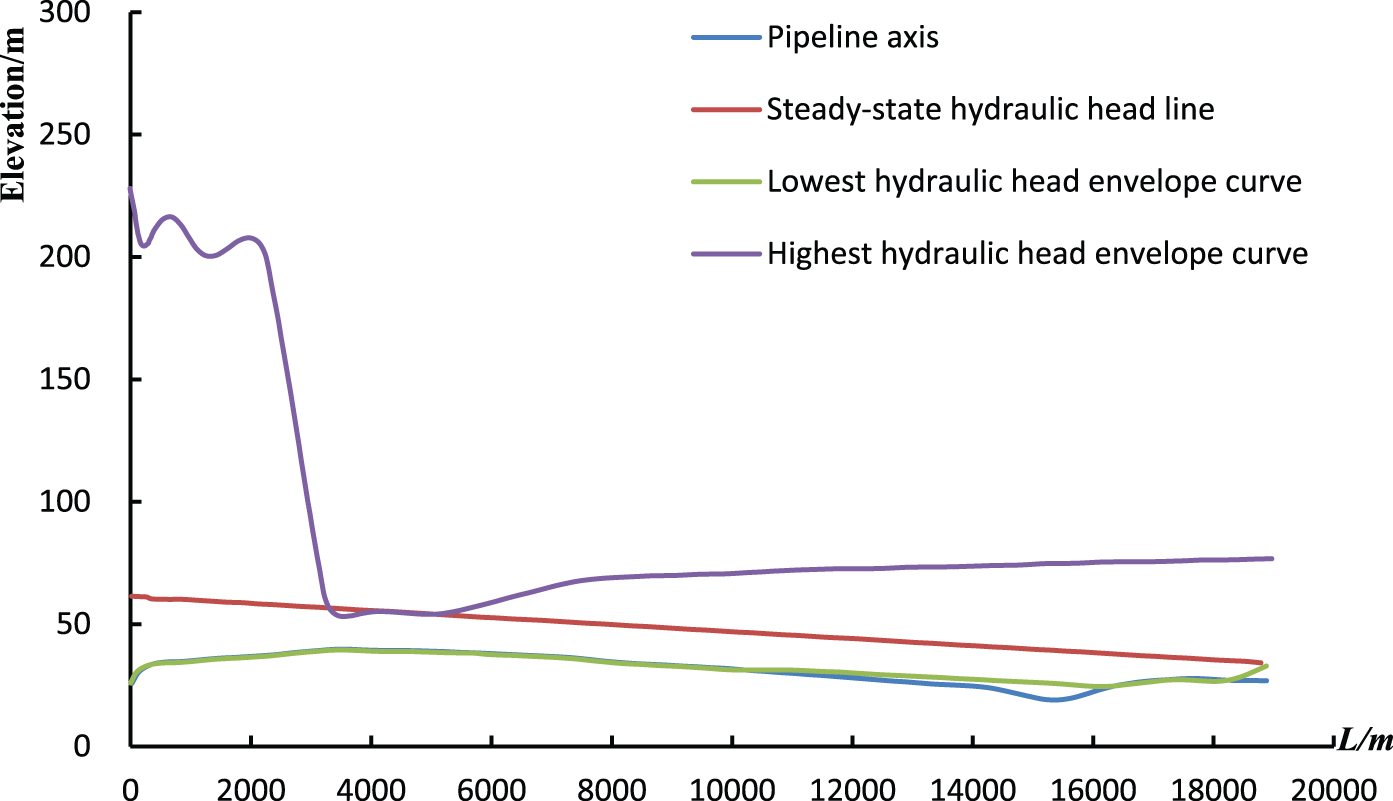
Lowest and highest hydraulic head envelope curves of the discrete model for buffered complete flow interruption-type air cavities.
Lowest hydraulic head envelope curve
The following observations can be made from Figure 8:
The lowest hydraulic head envelope curve generally coincides with the pipeline axis. The lowest water hammer value at most of the points along the pipeline is the elevation of the point, which indicates that liquid column separation occurs at most of the points on the pipeline due to the effect of the decompression wave. The lowest hydraulic head envelope curve of the pipeline section between 11,000 and 16,500 m is on the pipeline axis, which indicates that liquid column separation will never occur in this pipeline section.
Because the air valves automatically allow air inflow, the air inside a cavity that forms by liquid column separation remains at atmospheric pressure. Therefore, the lowest hydraulic head envelope curve of the pipeline will rarely be lower than the elevation of the pipeline axis, and few vacuum conditions will occur in the pipeline, which indicates that installing air valves at the high points of a pipeline is effective at controlling the vacuum values at each point along the pipeline.
Highest hydraulic head envelope curve
The following observations can also be made from Figure 8:
The maximum water hammer pressure head at the pump station is 61.35 m (maximum pressure head: 35.65 m), which is nearly identical to the steady-state pressure head; this indicates that the preventative measure for water hammers affects the transient pressure increase at the pump unit when it is shut down. Liquid column separation first occurs at monitoring points 2 and 7 due to the effect of the decompression wave, and air enters the pipeline via the air valves. The air cavities are then affected by the reflected water hammer compression wave, at which time the air valves are closed, and the air cavities have a buffering effect on the pressure increase that occurs due to the collapse of the air cavities.
Based on the maximum water hammer pressure head at each point along the pipeline, the pressure increases of each point in the pipeline section between the pipeline start and point 25 are effectively controlled, whereas the pressure increases at most points beyond point 34 are still relatively high. The increase in the water hammer pressure increases toward the end of the pipeline, and the excess maximum pressure head of the pipeline above the steady-state pressure increases. The maximum pressure heads of the pipeline are all greater than the stipulated 1.3–1.5 times the steady-state pressure head of the pipeline.
Transient data of the water hammer process at each monitoring point
The total calculation time is 400 s, and the time step is 0.22 s. The transient data at each monitoring point are stored every five time steps. Figure 9 shows the transient-state curve of the water hammer at monitoring points 2, 7, 16, 34, 52, and 80 during the water hammer process that occurs due to the air cavities.

Transient-state curve of the water hammer at each monitoring point.
Figure 9 and the longitudinal section of the pipeline (Figure 5) show that after the pump unit is shut down due to an incident, the pressure at each monitoring point begins oscillating. Liquid column separation first occurs at point 2 due to the effect of the decompression wave. The first liquid column separation continues for approximately 50 s. During this time period, air enters the cross section at monitoring point 2 via the air valve, and the pressure inside the cavity remains at atmospheric pressure. When the reflected pressurization wave acts on the air cavity, the air valve closes. The air cavity is compressed, and the pressure inside the cavity increases. The maximum water hammer value (61.4 m) is within the range of safe pressures of the pipeline and is also much lower than the increase in water hammer pressure caused by the collapse of the air cavity. Similarly, the maximum water hammer value at monitoring point 7 is 59.45 m, and the maximum pressure head is nearly identical to the steady-state pressure head value and is within the range of safe pressures of the pipeline, which indicates that the air cavity has a significant buffering effect on the pressure increase of the water hammer.
The water hammer pressure head at monitoring point 16 remains at the critical pressure head (40.1 m) for the entire process, which indicates that monitoring point 16 remains in the liquid column separation state after the pump unit shuts down. The water hammer pressure head oscillations at monitoring points 34, 52, and 80 are similar. No liquid column separation occurs at monitoring point 52. Separation only occurs at monitoring points 34 and 80 for relatively short durations in the initial stage after the pump unit is shut down. However, the hydraulic head is high, and the water hammer pressure increase is initially relatively significant at monitoring points 34, 52, and 80 after the pump unit is shut down; both far exceed the stipulated safety standards.
Conclusion
The water hammer preventive measure in which valves are installed at the beginning and end of a pipeline and air valves allow free inflow and outflow of air at each high point on the pipeline is effective at preventing the occurrence of vacuum conditions. Using this preventive measure, most of the lowest hydraulic head envelope curve will not be lower than the elevation of the pipeline axis. However, because the air valves allow free inflows and outflows of air, very large increases in water hammer pressure occur along the pipeline. The air valves are replaced by valves that only allow air inflow and prevent air outflow at monitoring points 2 and 7. This water hammer preventive measure is also very effective at preventing the occurrence of vacuum conditions. Most of the lowest hydraulic head envelope curve will not be lower than the elevation of the pipeline axis, and vacuum conditions will not occur along most of the pipeline. However, liquid column separation can still occur at most points because the increases in water hammer pressure along the pipeline are controlled by the buffering effect of the air cavities, and the increase in water hammer pressure near each air valve that only allows air inflow and prevents air outflow is within the range of safe pressures. However, the increase in water hammer pressure still exceeds the safe range at most points beyond the monitoring points. Therefore, the installation locations of the air valves and the setting of the valve actions should be based on the specific conditions. It is necessary to prevent the occurrence of new water hammers due to the collapse of flow interruption-caused air cavities that form by excessively rapid releases of air as well as to avoid residual air pockets that are caused by impeded air, which can also cause water hammers due to the collapse of air cavities in the pipeline.
Footnotes
Academic Editor: Jun Ren
Declaration of conflicting interests
The author(s) declared no potential conflicts of interest with respect to the research, authorship, and/or publication of this article.
Funding
The author(s) disclosed receipt of the following financial support for the research, authorship, and/or publication of this article: This work was supported by the special fund of Key Technology Project of safety production of major accident prevention and control (sichuan-0013-2016AQ), and Open Fund Project of Sichuan Key Laboratory of oil and gas fire fighting (YQXF201603).