
Abstract
Diagnosing rotor faults is considered as one of the most vital tools for health maintenance of rotating machinery. In this work, a smart diagnosis system based on automatic recognition of multiple rotor faults is developed. As rotor faults are comparatively complicated, the reasoning mechanism of composite nesting probability reasoning network knowledge expression and multiple reasoning methods are adopted. Besides, methods such as fuzzy pattern recognition and image analysis are also applied to conduct automatic recognition of fault symptoms like rotor vibration spectrum, shaft centerline orbit, and transient features. Also, this article attempted to propose artificial neuron network study and diagnosis methods on the basis of fractal features of faults, set up a smart diagnosis system based on automatic recognition of multiple rotor faults, and verify the feasibility of system diagnosis using a rotor practical fault diagnosis case.
Introduction
Rotors are key components or rotating machinery, and any failures in rotors may introduce unwanted downtime, expensive repair procedures, and even human casualties. As an effective component for condition-based maintenance, 1 the fault diagnosis has attracted much attention for rotor operations.
Rotor faults will result in abnormal changes in rotor vibration which can be spotted through monitoring and analyzing vibration signals.2–4 Li et al. proposed an order tracking technique based on local mean decomposition of the vibration signal. 5 Lei et al. 6 explored vibration characteristics in both time and frequency domains for the diagnostics of the planetary gearboxes. The vibration analysis under the condition of rotor faults can be comprehensively conducted from various perspectives such as vibration spectrum, phase, shaft centerline orbit, time-domain waveform, transient information, and statistical features. 7 These fault symptoms are usually shown in forms including spectral line, graph, or data, as well as determine diversified diagnosis knowledge forms. 8
To explore different symptoms for the fault diagnosis, Rafael et al. 9 combined acoustic emissions and vibration measurements to detect rotating machinery failures. Li et al. 10 developed deep learning method for the fault diagnosis. A criterion fusion approach was reported by Li et al. 11 for optimal demodulation of vibration signals. Chen et al. 12 proposed an intelligent diagnosis model including wavelet support vector machines and immune genetic algorithms.
Automatic recognition can be conducted on multiple knowledge forms in order to achieve useful driving information for smart diagnosis of system operations. Besides, complicated correspondence relations also exist between rotor faults and symptoms. Smart knowledge expression means must be adopted so as to express and comprehensively handle such complicated knowledge systems with multiples, factors, and forms as well as quantitative and qualitative perspectives.
Therefore, this work developed a smart diagnosis system based on automatic recognition of multiple rotor faults. At first, we introduce basic methodologies for the automatic fault recognition. The general structure and functions of the smart diagnosis system are subsequently developed. Then, the system is applied to a practical diagnosis. The last section is the part of the conclusions.
Methodologies
Systematic knowledge expression
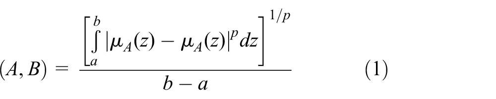
Due to the complicated relations between rotor faults and symptoms, a fault may lead to several symptoms, while a symptom can be caused by varied faults. 13 As a result, the system adopts the probability reasoning network based on such complicated cause–effect relations (as shown in Figure 1). Taking complexity of fault symptoms into consideration, symptom nodes are further divided to constitute a sub-network space which consequently can be deemed as a node in a larger space. In this way, a nested composite network expression pattern is established. For example, the sub-network of vibration spectrum features can be expressed in Figure 2 and it is composed of actual measure spectrum nodes, fault sample spectrum node, and converter. Actual measure spectrum nodes receive data. Compared with fault sample spectrum, proximity calculation can be adopted (as shown in formula (1)), and credibility is gained and delivered in order through converter. Besides, it is regarded as the credibility of vibration spectrum feature node spread to point to the credibility slot of fault frame node. 14

Network expression of rotor fault symptoms.

Sub-network of vibration spectrum features.
Automatic recognition of fault symptom
In this article, vibration spectrum, 15 shaft centerline orbit, 16 and transient 17 features are considered as representations for making the analysis.
Vibration spectrum features
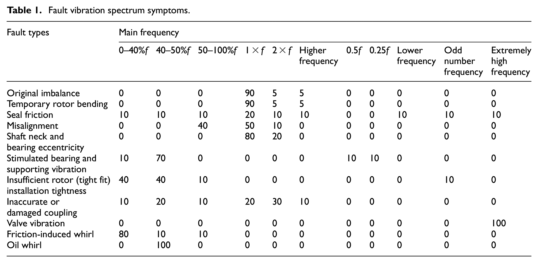
As the occurrence of rotor faults is demonstrated in certain spectrum distribution, the frequency range is divided into multiple characteristic frequency sections (or points). Calculated by the times of rotation frequency f, one may respectively obtain 0–40%f, 40–50%f, 50–100%f, 1×f, 2×f, higher frequency multiplication, 0.5×f and 0.25×f, lower frequency multiplication, odd number frequency multiplication and extremely frequency (the frequency greater than 10f). Maximum amplitude of all feature sections is calculated according to vibration spectrum analysis results of rotor vibration. The amplitude ratio is worked out and normalized (multiplied by 100) to obtain frequency feature vector Y = {y1, y2, …, yn}. Through comparing it with typical fault spectrum features, the affirmation of spectrum features for faults is obtained. Regarding the research works on typical fault spectrum feature distribution, a relative prominent case is shown in Table 1 (numbers in the table refer to the weight values of the amplitude distributions for vibration spectra of some typical faults in various bands).
Fault vibration spectrum symptoms.
In terms of spectrum feature recognition method, fuzzy pattern recognition 18 is applied and therefore the concept of proximity is introduced.
Suppose that F(Z) indicates the fuzzy set in discourse domain Z, and A and B are fuzzy vectors. A and B ∈ F(Z) and
where
Shaft centerline orbit
In rotating mechanical fault diagnosis, shaft centerline orbit of rotors is often regarded as one of important diagnosis bases. Pattern recognition and pattern analysis technology are used to realize automatic recognition of shaft centerline orbit of typical faults. Figure 3 shows the shaft centerline orbit features of some typical faults. 19
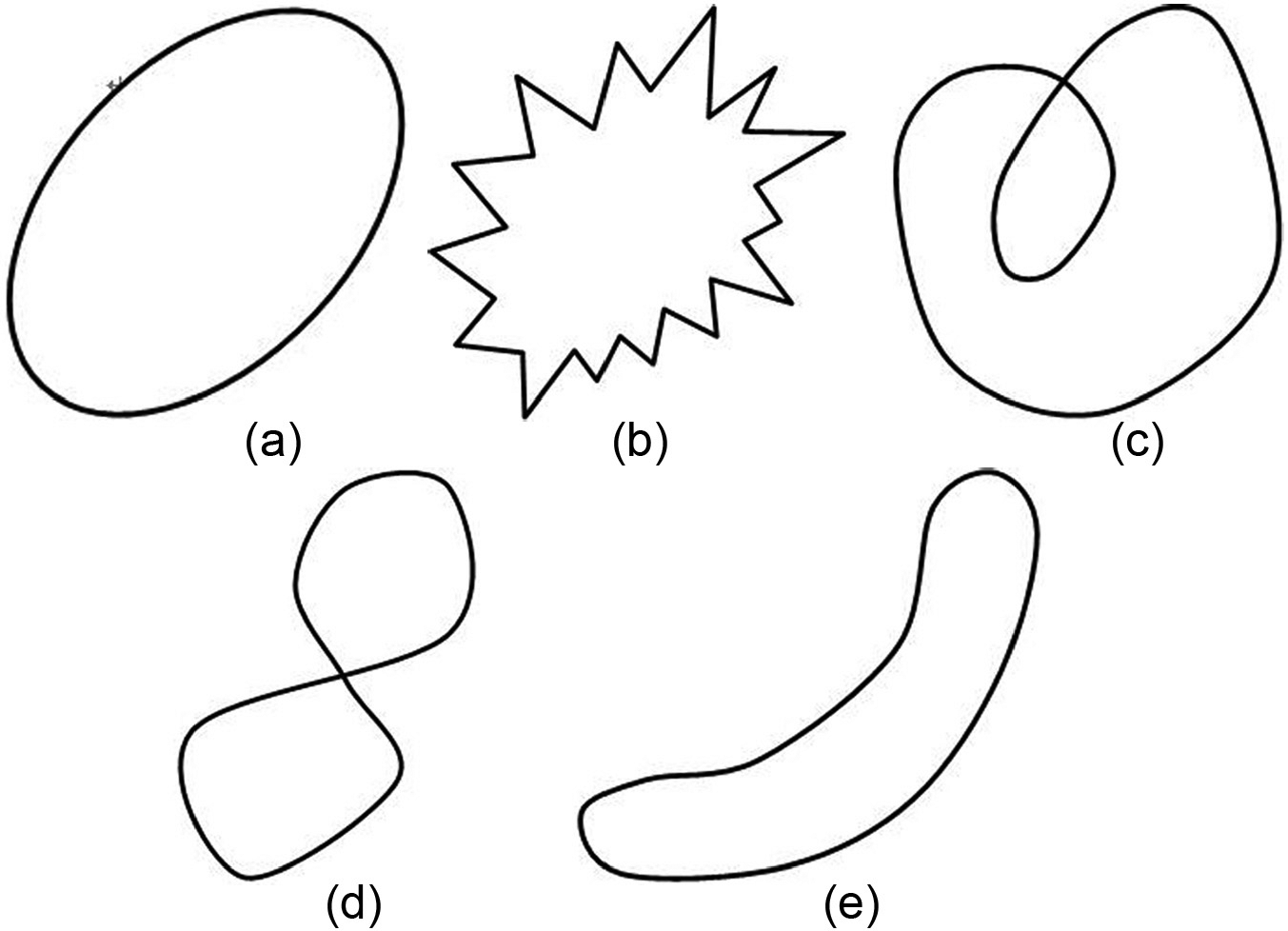
Shaft centerline orbit of several typical faults: (a) imbalance, (b) rub, (c) oil whirl, (d) misaligned, and (e) misaligned.
Hence, judgment factors are introduced:
Direction concavity. Direction concavity 20 Dφ is defined as the ratio between the total projection Ctφ of a curve in a certain direction φ and the projection width CWφ in the direction

In terms of Ctφ calculation, the curve can be divided into unit sections to calculate the project of a unit section in the direction line φ and sum can be solved. CWφ can be solved through calculating the maximum projection value of the curve in the direction line φ. Direction concavity can be used to describe the curve’s sunken degree in the direction.
Long axis. Long axis is defined as the direction section in which the maximum value of the distance between two points on the curve lies in. It can be solved based on search and comparison (set long axis distance is Dmax).
Short axis. The direction which is 90° with the long axis is defined as the short axis direction, and the maximum distance between two points parallel to the direction in the orbit map refers to the short axis (set short axis distance is Dmin).
Slender ratio (ovality) E. The slender ratio 21 is defined as ratio between the long axis and the short axis.
While judgment factors are used for pattern analysis, certain features of typical fault orbits should be concentrated on. For example, in Figure 3(b), there are a series of pointed points (acute angles) and pointed point calculation which can be conducted for judgment. There is a point of intersection in Figure 3(d), Dmin = 0 point can be searched in the direction parallel to the short axis direction; Figure 3(c) presents a dual-loop structure and the direction concavity at the long axis and short axis direction approaches 2 < Dφ < 4, and there is a point of intersection in the figure; in Figure 3(e), E >> 1 and Dmin > 0; the direction concavities at the long axis and short axis approach 2 as shown in Figure 3(a) and Dmin >> 0 and E > 1.
Differentiated recognition can be conducted in accordance with different features in the orbit. Besides, it can be judged whether its operation is stable or not based on different periods Dmax.
Transient features
Hereby, the amplitude change trend with the rotating speed in the process of switching on and off is taken as an example for explanation.
Besides, several basic features are categorized for amplitude change trend with the rotating speed, respectively, basically the same, gradual increase, gradual decrease, sudden rise in the amplitude, and sudden fall in the amplitude. Amplitude rate ξ is introduced, that is, change in unit rotating speed

Valve value range is set by tracking changes in ξ value during the process of switching on and off, and proximity calculation is conducted with change trend of typical faults, which can thus obtain belief factor.
Reasoning mechanism and system strategy
In terms of reasoning mechanism, the system adopts the plausible reasoning method based on “hypothesis test” in the diagnosis process. While dealing with multiple beliefs’ support or rejection for a certain conclusion, the system employs the theory of multiple beliefs’ support (or rejection) for the same fact being uncertain on the basis of the probability theory. 23 Besides, a lot of knowledge in the expert system 24 is based on experience, and experts need to diagnose and reason with incomplete knowledge. Therefore, the system uses default reasoning with incomplete knowledge. In addition, fuzzy reasoning is adopted for dealing with concrete information.
Plausible reasoning
In case of problem diagnosis, diagnosis hypotheses can be formulated according to characteristics of some initial information. These hypotheses can explain these initial information. Then, relevant features of these hypotheses can be further tested to gain more information until unanimous explanations are obtained for a certain conclusion to serve as a solution for the problem. It can be regarded as the circulating reasoning process of “hypotheses test.”
In the actual process of diagnosing the rotating machinery, it usually starts with frequency spectrum features to further instruct analyses of orbit feature, phase, waveform, and transient features, thus verifying and confirming the diagnosis in multiple aspects.
The theory of multiple beliefs’ support for the same fact being uncertain based on the probability theory
In the diagnosis process, it is inevitable to encounter belief integration due to multiple aspect analysis. This system employs the probability-theory-based approach to deal with multiple beliefs’ support (or rejection) for the same fact being uncertain.
Default reasoning
While diagnosing the rotating machinery, diagnosis reasoning is usually conducted without complete knowledge to obtain relatively reasonable conclusions. This requires processing or acceptance of incomplete information. For example, in the diagnosis, it is found that changes in the shaft centerline orbit of rotors basically take on an oval shape in the process of switching on and off. This phenomenon allows us to further cognize the imbalance failure of rotors. However, the fact, meanwhile, means that it is probably not the 8-shape or banana trajectory. caused by misaligned failure. Hence, it indicates a rejection belief for misaligned failure. Besides, we do not recognize the trajectory of some other failures, so we need to conduct default processing of their beliefs (such as approval of declining belief or constant belief).
In addition, the system uses other approaches such as fuzzy reasoning, like proximity calculation based on fuzzy pattern recognition.
Generally, the system provides different ways of reasoning for different tasks and is a reasoning mechanism which organically combines varied ways of reasoning.
System strategies mainly include reasoning strategy (direction), searching strategy, solving strategy, and limiting strategy. Regarding reasoning direction, the term produces a diagnosis conclusion through forward reasoning and then further verifies the veracity of the conclusion by conducting reverse test. Consequently, forward and backward reasoning strategy25,26 is applied. As for the searching strategy, the system goes for an inspiring searching strategy with breadth first and multiple goals. In order to solve the strategy, the system aims to work out a complete solution, given that there may be multiple faults. When it comes to the limiting strategy, in order to prevent excessive long reasoning from exceeding the time and space that can be afforded by computers, the system adopts a time–space limiting strategy.
Fault fractal feature study based on artificial neuron network
Vibration signal analysis is carried out on rotating machinery. Due to the influences of various nonlinear factors, the on-site signal is usually extremely complicated. All the time-domain waveform, shaft centerline orbit, and vibration spectrum of complicated vibration signals can be regarded as irregular graphs and can be studied using the method of fractal geometry. Fractal depiction 27 is quantitatively described on the basis of fractal dimension. Currently, proposed fractal dimensions include Kolmogorov’s capacity dimension, information dimension, correlation dimension, Hausdorff dimension, similarity dimension, box dimension, Fourier dimension, fuzzy dimension, and functional diagram dimension.
The sampling time sequence of vibration signals is taken for correlation dimension analysis.
Sampling time sequence is adopted as (X1, X2, …, Xi, …, XN), in which N can be deemed as the total number of sample points and Xi is the value measured at i moment. m sample points are taken out of the general sequence, that is, (Xi, Xi + τ,…, Xi + (m − 1)τ), where τ is time delay. In this way, K = N − (m − 1)τ dimension vectors can be obtained and these vectors support one embedding space.
The definition of correlation dimension 28 is as follows

where
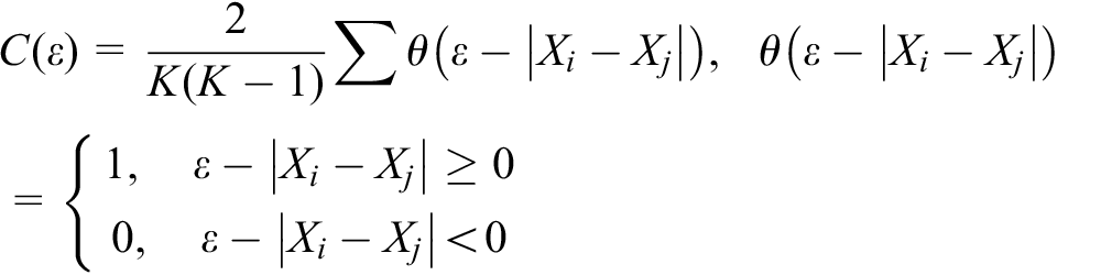
The distance of each two vectors in the embedding space is solved during concrete calculations. Each distance is regarded as an isodiametric ball which is let pass the “sieve” with a grid side length of ε. C value of balls “filtering” through the grids and C/NC are recorded (NC is the total number of balls). The number of ε is constantly changed to obtain a series of εi and Ci value. Besides, a coordinate system of lnCi/NC and lnεi is established. A straight line can be approximately obtained in the linear scale zone of εi (as shown in Figure 4). The slope of the straight line is considered as the correlation dimension D.

Correlation dimension fractal graph.
Complicated correspondence relations exist between rotor faults and symptoms. A fault might lead to multiple symptoms, while a symptom can be caused by multiple faults. Artificial neuron network is used to select fractal dimensions of fault symptoms as the input vector and target output is regarded as fault so as to investigate and diagnose. Hereby, the diagnosis issue is regarded as three-layer feed-forward network (Figure 5). BP algorithm 29 (back propagation algorithm) is used to study it.

Feed-forward BP network structure.
This is a forward network without feedback, and nodes in the network are one-way connected from the input layer to the output layer. Suppose that there is one input vector corresponding to any node in the network Uj. Node Opi in other layers is its input. Through the role of weight matrix Wji (multiply), the sum is solved to obtain the weight sum of node Uj (Figure 6)


Interconnection diagram of a certain node.
Then, action function is conducted to obtain the input of node Uj

That is to say, each input vector is imported into the network based on the input layer. According to the above methods, each node of each layer is calculated (usually for nodes in the input layer, signals directly pass without action function). In the end, an output vector is obtained in the output layer, which is the forward-propagating process. If expected output cannot be gained in the output layer, it will turn into backward-propagating process. Error signal will turn back layer by layer along the original connection access. Through revising the connection weight value of each layer of neuron, the output of the output layer can approach expected output to the utter most. Therefore, a square error function is introduced

where tpj is the expected output corresponding to the input vector and Opj is the actual output of output nodes. The error function of all input vectors being studied must be the minimum. The gradient descent method can be adopted to address this problem. BP algorithm flow chart is shown in Figure 7.
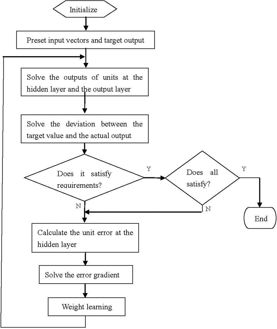
BP algorithm flow chart.
General structure and functions of the system
Figure 8 presents an expert system module structure chart for rotor fault diagnosis. The system mainly comprises four parts: pattern base, data base, process base, and rule base. Function modules such as fault diagnosis, conclusion verification, consultation and maintenance, knowledge self-study, fractal features, and diagnosis can be realized. Then, technical components and main function modules of the system are introduced as follows.

Expert system module structure chart for rotor fault diagnosis.
Technical components
Four technical components are described as follows:
Pattern base. It is also called pattern library, which is a basic unit with predicates as knowledge expression. Each predicate is regarded as an image (or pattern) and image matching is the basic way of reasoning. Besides, images are divided into predicate images and parameter images. The defined predicate image in pattern base is composed of a predicate and a group of (sequenced) formal parameter images. It regulates the number of parameters, sequences, and types for substitution of actual parameter images (in data base) as well as half-actual parameter images (in rule base). Parameter images are composed of image primitives.
Data base. It is used to define the data searching space of reasoning. There are two kinds: one is used for input, being the known prerequisite reserved knowledge of reasoning, and the other is used for output to store reasoned results. Besides, consultation data base is set to store transient input data. Images of predicates appearing in the data base must have been defined in the pattern base. Each data base is a world, and the same predicate can have different true and false values in different worlds. If a predicate P shows up in one data base, any predicate P′ which can be matched with P, the matched predicate has a true value in the world.
Process base. It is used to store to-be-called function bodies in the operation system.
Rule base. It consists of rules and each rule represents a reasoning step. Each rule base indicates the entirety of rules which are allowed to be used in a reasoning process (or sub-process). Each rule base has a level. The lower the level number, the higher the level. Advanced rule base can control the operation of low-level rule base through the control process provided by the system, which also plays the role of meta-rule. The level of zero-level rule base is the highest from which the entire system is launched.
Main function modules
Main menu. As a zero-level rule base, it plays the role of launching and controlling rule bases of lower level such as diagnosis reasoning module, consultation and maintenance module, knowledge self-study module, fractal features, and diagnosis module.
Diagnosis and verification module. The solving process of the system diagnosis is as follows: first, original information is used to work out preliminary diagnosis conclusions and further conduct induction test and hypothesis on relevant feature information of the conclusion until unanimous explanatory conclusion is reached as the solution of the diagnosis. In addition, relevant information can be further utilized to verify based on user demands until the knowledge library is emptied. During the diagnosis process, according to different on-site conditions, the system can provide two methods of online automatic diagnosis and offline manual input diagnosis, and the diagnosis process flow chart can be found in Figure 9.
Consultation and maintenance module. The consultation and maintenance module can provide consultation and maintenance suggestions for diagnosed faults so as to take action in time. Besides, it can also be considered as general consultation learning for system faults.
Knowledge self-study module. The module has functions such as displaying, deleting, revising, and adding system knowledge. The learning process can be conducted according to certain requirements of the system, thus providing a user-friendly man–machine conversation function.
Fractal features and diagnosis module. The module can conduct fractal feature analysis on signal sequence and calculate correlation dimension in the fractal scale zone, as well as establish a feed-forward neuron BP network for fault diagnosis of rotating machinery with dimensions and faults as the input and output vectors. The network is constantly trained to enrich the knowledge and obtain desirable diagnosis effect. Fractal features and diagnosis module structure chart is shown in Figure 10.

Diagnosis process flow chart.

Fractal features and diagnosis module structure chart.
The system can diagnose more than 10 kinds of faults. The inputs of the diagnostic network include the time-domain signal, shaft centerline orbits, and transient information.
C language and Tuili language programming are used in the system, which can be operated on common computers.
Diagnosis experiment
The diagnosis experiment is conducted on a double-span rotor experiment platform with four supporting structures (as shown in Figure 11). The middle part of a shaft far away from the engine has a horizontal crack (the crack is directly fabricated on the shaft based on a high-frequency fatigue machine, and the depths of cracks are observed microscopically by means of surface sanding tool, and the measurement is controlled at 1/4 of shaft diameter which is 12 mm). Gaskets are added on the 4# bearing block base, and the height of the gasket is 0.4 mm, thus changing the alignment status of the original rotor system.

Rotor experiment platform chart.
Electrical eddy current displacement sensors are, respectively, installed at the horizontal and vertical directions of the measurement points 1–6 along the rotor shaft. Vibration signals and photoelectric signals of all points are sent to the dynamic balance meter, CF500 frequency analyzer, and (TEAC, Japan) tape recording device. The engine is launched to exceed the critical speed of rotation (around 3200 r/min), that is, 4100 r/min. Then, the speed is lowered until stop.
The real-time frequency analysis in the experiment process is shown in Figure 12, and the time-domain waveform is indicated in Figure 13. The obvious “8” shape shaft centerline orbit in the launch and stop process is displayed in Figure 14, while the three-dimensional graphs of acceleration and slow-down of rotors can be observed in Figures 15 and 16.

1200 r/min vibration frequency chart at 5# point.
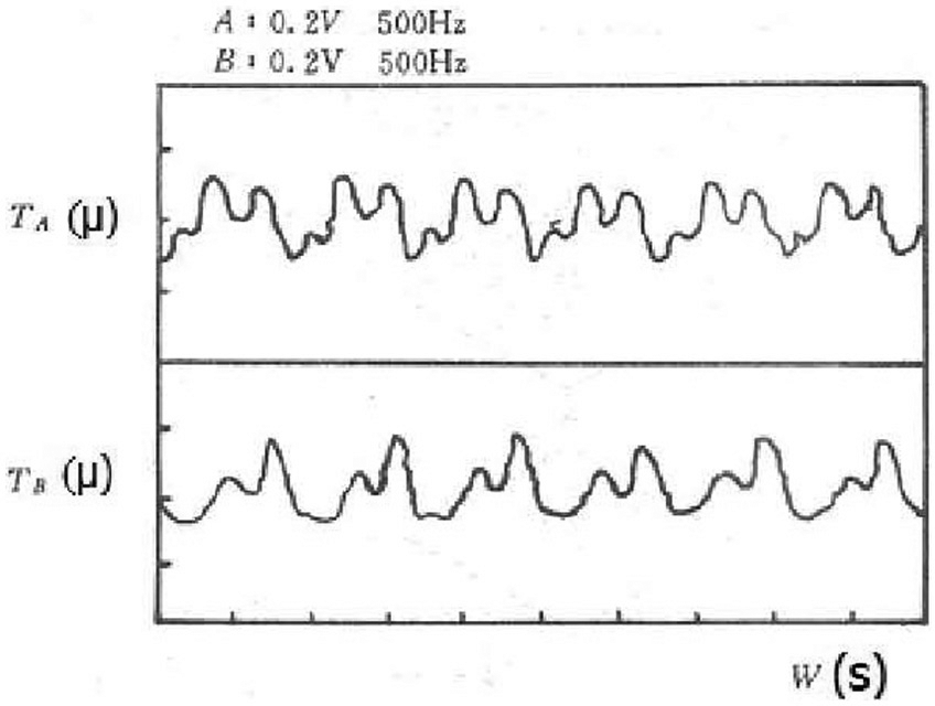
Time domain waveform with a vibration of 1200 r/min at horizontal and vertical directions at 5# point.
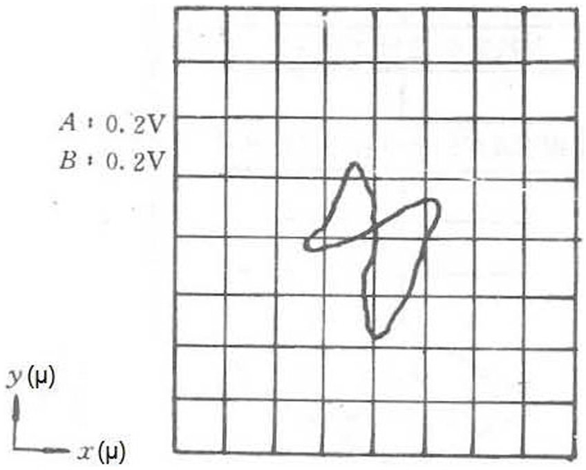
Shaft centerline orbit at 5# point.
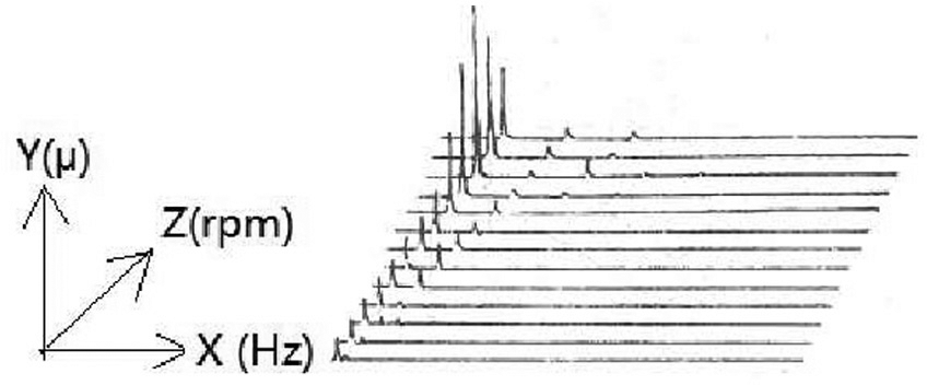
Three-dimensional acceleration spectrum chart at the vertical direction at 5# point. (The rotating speed rises from 500 r/min with an interval of 300 r/min.)

Three-dimensional deceleration spectrum chart at the vertical direction at 5# point. (The rotating speed rises from 500 r/min with an interval of 300 r/min.)
Comprehensive diagnosis results of the expert system are as follows: rotor crack fault, credibility 0.82; misalignment fault, credibility 0.77; initial imbalance, credibility 0.6.
Conclusion
Such nesting composite network has strong knowledge expression capability and can completely demonstrate correlations between knowledge.
Automatic recognition is conducted on multiple complicated knowledge forms of fault symptoms. Besides, it can automatize the diagnosis process and make it possible to realize online automatic diagnosis of the smart system.
The mechanism with coexistence of multiple reasoning methods and full system strategy makes the system better reflect the complicated thinking mechanism of the diagnosis process and also make the system control process more rigorous and orderly.
The fractal dimension description of fault symptoms provides an effective way of analyzing and diagnosing complicated faults. With the application of fault fractal feature establishment, the powerful study function of neuron network is used to keep training the network, enrich knowledge, and further realize favorable diagnosis effect.
The possibility of system diagnosis is verified through practical examination of varied concurrent faults.
Footnotes
Academic Editor: Dong Wang
Declaration of conflicting interests
The author(s) declared no potential conflicts of interest with respect to the research, authorship, and/or publication of this article.
Funding
The author(s) disclosed receipt of the following financial support for the research, authorship, and/or publication of this article: This work was supported by the International S & T Cooperation Program of China (2013DFG60080) and the Research Program of Higher Education of Guangdong (2016KZDXM054 and 2016KQNCX165).