
Abstract
The single-motor full hybrid electric vehicle tends to suffer drivability and excessive clutch wear issues during the mode transition from electric driving to hybrid driving because the single motor must simultaneously propel the vehicle and divert torque via clutch engagement to start the engine. In this study, a novel four-phase compound robust control method consisting of the feedforward–feedback technology and the robust compensation approach is proposed to address these problems during the mode transition. The whole mode transition process was divided into four consecutive phases according to the operating status of engine and clutch. In each phase, a nominal controller based on the feedforward–linear quadratic regulator feedback technology is first designed for the nominal linear model to guarantee a desired control performance. And then, the nonlinear uncertain part of the engine/clutch torque and the vehicle resistant torque as well as the model parameter uncertainties are all considered as equivalent disturbances, and a robust compensator is introduced to suppress the effect of equivalent disturbances. Simulation is performed to validate the effectiveness of the proposed control method. The results show that the four-phase compound robust control method can achieve better vehicle drivability and minimize clutch wear during the mode transition from electric driving to hybrid driving even in the presence of various torque disturbances and parameter uncertainties.
Keywords
Introduction
Due to strict emission regulation and high fuel economy requirements, the development of environment-friendly electric vehicles have become a priority in the automobile industry. Hybrid electric vehicles (HEVs) are widely considered to be a promising technology in addressing the strict regulation on fuel economy and greenhouse gas emissions. 1 HEVs have multiple power sources, and their fuel economy and emissions can be optimized by energy management strategy. As a result, under the supervision of the energy management strategy, HEVs frequently make transitions between different modes to achieve an optimal power distribution. However, HEVs tend to suffer some issues such as drivability and excessive clutch wear during mode transitions.2–4
For the single-motor full hybrid electric vehicle (SM-FHEV), there exists a special vehicle drivability deterioration issue during the mode transition from electric driving mode to hybrid driving mode (hereafter called EV-to-HEV). As the single motor must simultaneously propel the vehicle and divert torque via clutch engagement to start the engine. 4 The clutch friction torque introduces nonlinear dynamic to the powertrain, and a sharp torque fluctuation may occur due to the abrupt engine nonlinear torque transferring into the driveline when the clutch is locked up. Obviously, the vehicle ride comfort will be severely degraded. Moreover, the engine start and the engine-motor speed synchronization are implemented by clutch engagement. However, clutch slipping for a long time will produce a large amount of frictional loss. Especially in urban area, frequent EV-to-HEV mode transition will further aggravate the wear of clutch. In this study, we aim to propose a novel control method to coordinate the motor, engine, and clutch during EV-to-HEV mode transition in order to improve the vehicle drivability and minimize clutch wear for the SM-FHEV.
Several research projects have focused on the EV-to-HEV mode transition control for the single-motor HEVs. Kum et al. 4 applied dynamic programming algorithm to solve the optimal control strategies to achieve the balance between the vehicle drivability and quick engine start during mode transition for a single-motor parallel HEV. It was assumed that clutch torque can be accurately estimated and perfectly canceled by motor. However, there are errors of clutch torque control because of the nonlinear characteristics of the actual clutch torque response. Anthony et al. 5 investigated the EV-to-HEV mode transition of a single-motor parallel HEV, and they proposed a control strategy of motor torque feedforward compensation control based on constant clutch torque. However, the performance of the motor torque feedforward compensation is totally dependent on the clutch torque estimation. Liu et al. 6 also utilized the control method of motor torque feedforward compensation control based on constant clutch torque but added a proportional–integral–derivative (PID) feedback controller based on speed tracking in motor torque control to suppress the torque estimation error–induced disturbance for a single-motor parallel HEV. However, the effect of system parameter uncertainties was not considered. Dai et al. 7 proposed a coordinated control strategy using clutch pressure PID control and motor torque compensation to achieve a seamless EV-to-HEV mode transition for a parallel hybrid vehicle. Zhu et al. 8 designed a coordinated control strategy using fuzzy gain-scheduling PID control to regulate the mode transition of single-motor hybrid vehicle. Taking into account the uncertainties of controller area network (CAN) communication time delays between the vehicle control unit (HCU) and component control units during mode transition, Zhang et al. 9 presented a robust controller based on the mu-synthesis method to realize a smooth EV-to-HEV mode transition for a parallel hybrid drivetrain. In addition, Alt et al. 10 proposed a flatness-based feedforward and a feedback controller for the engine and motor to guarantee the good tracking behavior between the actual output torque and the demand torque during the mode transition.
Although the above-mentioned research studies give great insights for the EV-to-HEV mode transition control problem, there are still some shortcomings. First, it was assumed that the engine and clutch are well modeled and perfectly follow their torque commands, the nonlinear characteristics of engine and clutch torque were not considered carefully. Second, system parameter uncertainties were generally ignored in these studies. In fact, the system parameters are time variant because of the change of gear shift and the variation of the total vehicle mass caused by the change in the number of passengers and the weight of baggage. Thus, the nonlinear torque (engine and clutch) and the model parameter uncertainties will deteriorate vehicle drivability. Moreover, in the above studies, after engine was ignited, the clutch was still in slipping control until the engine and motor speed fully synchronize. However, clutch slipping for a long time will produce a large amount of frictional loss. Especially when single-motor hybrid vehicle is operated in urban area, the EV-to-HEV mode transition happens frequently, which will further aggravate the wear of the clutch. Therefore, the main purpose of this study is to propose a novel mode transition control method to address the issues of vehicle drivability and excessive clutch wear during the EV-to-HEV mode transition for the SM-FHEV.
The remainder of this article is organized as follows: the configuration of the investigated SM-FHEV is introduced in section “Configuration of the HEV.” And then, the system dynamic model, the engine model, and clutch model are described in section “SM-FHEV dynamic modeling.” Next, in section “Robust control design for mode transition,” the mode transition process from EV-to-HEV is divided into four consecutive phases according to the operating status of engine and clutch. The nonlinear characteristics of engine/clutch torque and vehicle resistance torque and the parameter uncertainties are taken into account simultaneously, and a novel four-phase compound robust control method consisting of feedforward-feedback technology and robust compensation approach is presented. Finally, simulation results and analysis are conducted in section “Simulations and analysis” to show the effectiveness of the proposed controller in improving vehicle drivability and minimize clutch wear under various nonlinear torque disturbances and parameter uncertainties.
Configuration of the HEV
Figure 1 illustrates the powertrain of the investigated SM-FHEV. This hybrid system is configured by removing the torque converter from a conventional automatic transmission and installing a one-way clutch (OWC), a wet multi-disk clutch (WMC), and a single electric motor (EM). The OWC is unlocked when the engine speed is lower than EM speed. Conversely, it is locked to ensure the engine and EM speed synchronization. The WMC is a key competent in hybrid powertrain. When the WMC is disengaged to separate the engine from the driveline, the vehicle uses only the EM for propulsion and regenerative braking with high efficiency, eliminating the friction and pump loss of the engine. When the driver depresses the accelerator pedal beyond the EM drive region, the WMC is engaged so that the EM can start the engine. After the WMC is locked, the vehicle is accelerated by adding the engine torque to the EM torque.

Schematic diagram of the single-motor full hybrid vehicle.
SM-FHEV dynamic modeling
System dynamic model
A simplified lumped parameter dynamic model of the SM-FHEV is developed, as shown in Figure 2. In this figure, Te is the engine torque (resistant torque in engine cranking and traction torque after ignition). Tm is EM torque. Tcl is the clutch torque. Tv is the vehicle resistant torque with respect to the drive shaft. Je is the equivalent inertia of the engine crankshaft, flywheel, and wet clutch driven plates. Jm is the equivalent inertia of the EM shaft, wet clutch driving plates, and transmission shaft. Jv is the equivalent inertia of the wheels and the vehicle mass acting on the wheels. ωe, ωm, and ωv are the rotate speeds of engine, EM, and wheel, respectively. ig is the gear ratio of the multistep automatic transmission, which is assumed as a constant during mode transition. ks is the equivalent torsional stiffness of the drive shaft, and ce, cm, cv are damping coefficients of engine, EM, and wheel, respectively. Note that the equivalent damping coefficient of the drive shaft is not considered in the SM-FHEV model because the stiffness of the drive shaft is much larger than the damping coefficient.
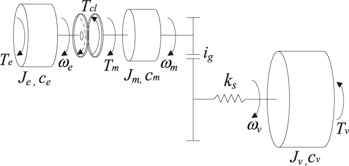
Schematic diagram of the SM-FHEV model.
According to the operating status of the wet clutch, the dynamic equations of the SM-FHEV can be expressed as follows:
1. Clutch slipping process
When the wet clutch is slipping, the dynamic equation of the drivetrain is given as

where θm and θv are the rotational displacements of the EM and wheel, respectively.
2. Clutch locked up
After the wet clutch is locked, the dynamic equation of the drivetrain is written as

The engine model
Engine subsystem has a nonlinear delay characteristic. An investigation carried out by Karlsson and Fredriksson 11 showed that the mean-value engine model (MVEM) is sufficient for use in powertrain simulations and for powertrain control design. In this article, a simplified MVEM is applied to represent the engine dynamic torque response. 12 The relationship between the engine torque request and the indicated torque in frequency domain is given as

where Tei is the indicated engine torque; Ter is the engine torque request from the HEV controller; τice is the engine speed-dependent time constant of the first-order lag, indicating the response from the throttle to the torque; and δice represents the engine speed-dependent time delay caused by air filling in the manifold and the fuel injecting.
Then, the actual engine output torque can be calculated as

where Tef is the engine frictional torque, and it can be approximated as a quadratic function of the engine speed 8

where a2, a1, and a0 are the engine friction coefficients, which can be identified from an experimental motored test.
The wet clutch model
The wet clutch is a key component to realize the EV-to-HEV mode transition for the SM-FHEV. The clutch model is applied to determine the transmitted torque of clutch in different operating states, which includes the clutch torque model and the hydraulic clutch actuator model.
In the dynamic process of clutch separation or engagement, its operating state can be divided into open, slipping, and locked phases based on the clutch pressure and speed difference between the driving and driven plates. The clutch torque in different operating phases can be expressed as 13

where A is the clutch piston area; Z is the number of clutch disks; Rm is the effective radius clutch disks; Pcl is the hydraulic pressure of clutch; Pth is the return spring pressure; Pcls is the locking clutch pressure; Tcli is the input torque when clutch is locked; sgn(·) is the sign function; ωrel is the rotational speed difference between the clutch driving and driven plates; µs is the static friction coefficient; and µd is the dynamic friction coefficient, which can be approximately expressed as 14

where µ0, µ1, and γ are the constant parameters governing the large slipping speed, the low slipping speed, and the rate of change of friction with changes in slipping speed, respectively.
According to equation (6), when the structure parameters of wet clutch are determined, the clutch torque is mainly determined by the hydraulic pressure Pcl. The hydraulic pressure of the wet clutch is controlled by the solenoid in the hydraulic actuator system. The clutch actuator dynamic from the pressure command Pclr can be simplified as a second-order system, 8 which is expressed as

where ωn is the natural frequency, which takes the value of 77 Hz, and ζ is the damping factor of 1.49.
Robust control design for mode transition
The control objective of the EV-to-HEV mode transition is quickly increasing engine speed to match speed of transmission input shaft (i.e. EM speed) using a coordination control of EM, engine and clutch, and avoiding torque disturbances transferred to the vehicle body. Owing to the dynamics of the hybrid powertrain system are changed during mode transition, the EV-to-HEV mode transition process can be divided into four consecutive phases according to the operating status of engine and clutch, including engine cranking phase, engine and EM speed synchronization phase, clutch engagement phase, and power sources (engine and EM) torque coordination phase.
Figure 3 illustrates the diagram of the four consecutive phases. 2 The vehicle is operated in EV mode at low speed, when the vehicle speed is greater than the threshold vehicle speed uth, the engine is cranked up by the friction torque of the engaging wet clutch (engine cranking phase). When the engine speed is increased up to its idle speed ωid, the wet clutch is disengaged quickly, and the engine is ignited and accelerates to synchronize with the EM speed (speed synchronization phase). When the speed difference ωrel between the engine and EM is less than the threshold speed difference ωth, the wet clutch starts to engage itself again (clutch engagement phase). When the wet clutch is locked, the engine and EM are controlled to follow their torque commands Ter and Tmr assigned by energy management strategy (torque coordination phase). When the engine and EM torque reach their respective torque command, the EV-to-HEV mode transition process is completed. The vehicle is operated in HEV mode.

Diagram of the operating phase.
Accordingly, the mode transition control algorithms should be independently designed in each phase. During the mode transition, there are three control input candidates, the EM torque Tm, the engine torque Te, and the clutch torque Tcl. The control inputs are determined by the operating state of the control element and the control feasibility in each phase.
In engine cranking phase, the engine is cranked up, and the control inputs are the clutch torque Tcl and EM torque Tm. In speed synchronization phase and clutch engagement phase, there are three controlled inputs (Te, Tm, and Tcl) and two outputs (ωe and ωm). Hence, the control system is over-actuated, and there are theoretically countless control solutions. However, if one of the three inputs is predefined, then the input combination of the other two has only one solution. Since the EM is the main power source of the vehicle during the mode transition of interest, the EM Tm is a necessary control input. The engine torque is usually small and tends to fall into a low-efficiency area of the engine operation in these two phases. The use of clutch torque control can avoid low-efficiency operation of the engine but cause higher clutch frictional loss.
In this study, the reducing clutch frictional loss is considered as more important than achieving high engine efficiency during the mode transition. One reason is that the large friction torque and long engagement durations may produce a large amount of frictional losses, which will aggravate the wear of the clutch. The other reason is that the two phases are completed in only a few seconds, and the time spent in transition is a relatively small fraction of the entire engine operation, and the influence of the mode transition on engine efficiency is almost negligible. 15 In addition, the speed synchronization based on clutch slipping control for a single-motor parallel HEV has been verified by bench test, but it is difficult to accomplish. 5 Therefore, it is reasonable to avoid the clutch torque Tcl and apply the combination of engine torque Te and EM torque Tm as much as possible in speed synchronization phase and introduce a small constant clutch torque Tcl to engage the clutch quickly in clutch engagement phase. In torque coordination phase, the clutch is locked, and the accuracy and response time of the EM torque control are much better than that of the engine. Therefore, the EM torque Tm is selected to be the main control input.
In order to improve the vehicle drivability during the EV-to-HEV mode transition, the torques of the EM, engine, and clutch need to be coordinated with each other in the four phases. However, owing to the nonlinear characteristics of the engine and clutch torques, there inevitably exist undesired torque fluctuations in the driveline. Moreover, the parameters in the dynamic model are time variant because of the change of gear shift and the variation of the total vehicle mass caused by the change in the number of passengers and the weight of baggage. The above characteristics of the investigated dynamic system increase the difficulty of controller design.
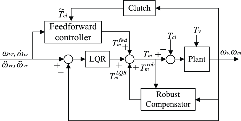
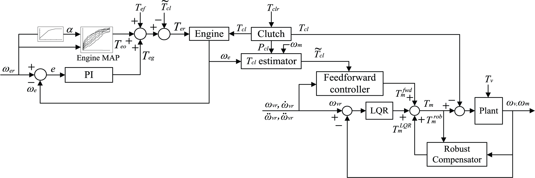
To address these problems, a compound robust control method consisting of feedforward–feedback technology and robust compensation approach is presented in this article. The principle of the compound robust control system is illustrated in Figure 4. In this method, the nonlinear uncertain part of engine/clutch torque and vehicle resistant torque as well as the model parameter uncertainties are considered as equivalent disturbances. The system model can be rewritten as a linear model with equivalent disturbances. A nominal controller based on the feedforward and linear quadratic regulator (LQR) feedback control technology is first designed for the linear model to guarantee a desired control performance. And then, a robust compensator is introduced to suppress the effect of equivalent disturbances.

Schematic diagram of the compound control method.
According to the structure of the controller in Figure 4, the control input ui can be expressed as

where ufw is the feedforward control input, ufb is the feedback control input, and urb is the robust compensating control input. The detailed control strategy of power sources and clutch in each phase is designed in the following.
Engine cranking phase
Because the engine is cranked up by wet clutch slipping in this phase, the clutch torque
will drag the hybrid drivetrain, leading to poor vehicle drivability. It is assumed that
the crankshaft rotate speed is uniformly accelerated in engine cranking phase, and the
engine starting time is about 0.4 s.
16
Thus, the required clutch torque is
equal to the sum of the engine frictional torque and the inertial moment of crankshaft,
that is
The EM not only propels the vehicle but also compensates for the clutch torque and suppresses the vibration in driveline caused by time-varying parameter perturbations and load torque uncertainties in engine cranking phase. In this study, the compound robust control method mentioned above is applied for EM torque control. Figure 5 illustrates the control structure of the EM in engine cranking phase. The detailed derivation process is described in the following.
Control structure of the EM in engine cranking phase.
From equation (1), the EM side plant can be rewritten as

In order to take into account the nonlinear torques and parametric uncertainties, the dynamic equation (10) can be described as follows

where ami and avi (i = 1–4) represent model parameters with uncertainties and take the forms

where Δami and Δavi
(i = 1–4) are the parametric uncertain parts.

where
Similarly, the nonlinear torques Tcl and Tv can be expressed as follows

where
Thus, the dynamic equation (11) can be rewritten as

where

where qmd(t) and qvd(t) are called the equivalent disturbances, which include the parametric uncertainties and the nonlinear uncertain parts of the clutch torque and vehicle resistant torque.
Differentiating both sides of the differential equation about the wheel speed

Further differentiating equation (17), we obtain

From equations (15), (17), and (18), a differential equation can be derived as follows

where

Define wheel speed tracking error as

And define state variable Xe as

where
Then, the error system of EM side plant can be described in a state-space form as

where

As shown in Figure 5, the EM controller is composed of three parts: a nominal feedforward controller, a nominal feedback controller based on LQR, and a robust compensator. Therefore, the control input Tm takes the following form

where
Nominal feedforward controller design
The nominal feedforward controller is given by

This controller is used to obtain a nominal linear error system in order to design the LQR controller and robust compensator.
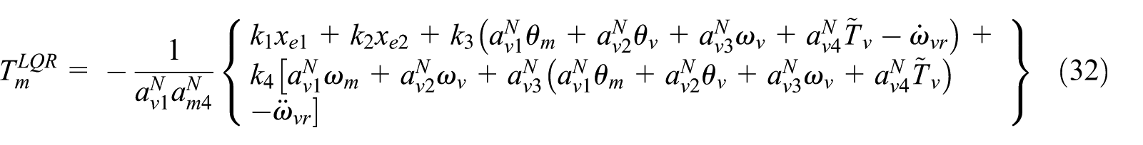
Nominal LQR feedback controller design
Ignoring the equivalent disturbance, the nominal LQR control input

If the cost function is defined as follows

where Q is a symmetric and positive definite matrix and R is a positive constant.
The LQR controller can be expressed as

where the state-feedback gain K can be written as 17

where P is the positive definite solution of Riccati equation as follows

Substituting equation (28), equation (26) can be rewritten as

However, the states
where
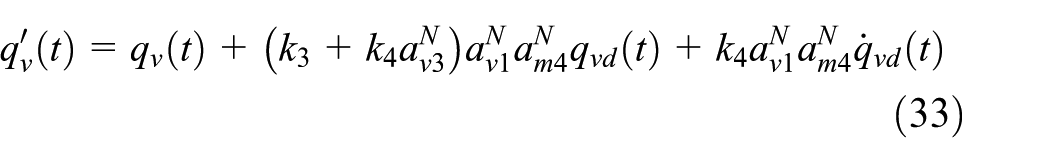
where
Robust compensator design
Considering the total equivalent disturbance

In order to suppress the influence of the total equivalent disturbance
where

where f1 and f2 are the positive constant values to be determined.
If f1 and f2 are sufficiently
large, one can expect that the robust filter F(s) can
have a sufficient wide frequency bandwidth within which the gain of the filter would
approximate to 1, and
Due to the states xe3 and xe4
cannot measured, defining

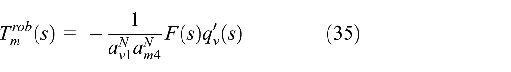
From equations (35)–(37), the robust compensator in frequency domain can be calculated as
Theoretically, the capability of robust compensator to suppress equivalent interferences is better with larger parameters f1 and f2. However, in practical application, if the parameters are too large, the more high-frequency noise can also pass the robust filter F(s). The ability of robust compensators to suppress equivalent interferences will be reduced. Therefore, the robust control parameters must be chosen according to the characteristics of nonlinear torques and system parameter uncertainties.
Speed synchronization phase
When the crankshaft speed reaches up to 800 r/min, the engine is ignited and accelerates quickly to synchronize with the transmission input shaft speed, which is equal to the EM speed. In order to reduce the abrasion of clutch friction disks, the wet clutch is disengaged before the engine ignition. Hence, the clutch torque Tcl drops quickly to zero. After ignition, the engine speed needs to be controlled to synchronize with the EM speed in a short time. 19 In this phase, control accuracy is less demand in engine side. Thus, a compound controller based on feedforward and proportional–integral (PI) feedback is designed to regulate the engine speed. The control principle is shown in Figure 6.

Schematic diagram of engine speed control.
In Figure 6, the feedforward control part first uses the engine no-load characteristic curve (as shown in Figure 7) 20 to obtain the throttle opening of the engine target speed. Then, the feedforward engine torque Teo can be obtained by engine static characteristic map. Meanwhile, a feedback controller based on PI method is added to produce regulated torque Teg. Thus, the required engine toque Ter can be written as


Engine speed curve under unload condition.
The EM still uses the compound robust control method shown in Figure 5. It should be noted that since the wet clutch is disengaged in this phase, the EM no longer compensates for the clutch torque.
Clutch engagement phase
When the speed difference between engine and the transmission input shaft is approaching
to a threshold speed
Control structure in clutch engagement phase.
The required clutch torque Tclr is the transferred torque at
clutch slip–stick point. The engine and EM angular accelerations are equal to each other
at this point, that is,

The engine is still in speed control, just as described in speed synchronizing phase. However, the engine speed is disturbed by the clutch torque. Thus, a feedforward control is added into the engine speed control to compensate for the clutch torque disturbance. Thus, the required engine toque Ter in this phase can be written as

The EM control in this phase is the same as in engine cranking phase, as mentioned before.
Power source torque coordination phase
After the slip–stick transition, the wet clutch is locked, and the vehicle enters into hybrid driving phase. The engine and EM will make the transition from the current torque to the required torque assigned by the energy management strategy. However, owing to the nonlinear characteristic of engine dynamic torque, the engine torque ripple will cause a large torque fluctuation in driveline. By contrast, the EM has the characteristics of fast torque response and high control precision. Therefore, the EM can be applied to suppress torque vibration fluctuation in driveline in this phase. The compound robust control method based on feedforward–feedback technology and robust compensation approach mentioned above is still applied for EM control in this phase. The control structure is shown in Figure 9.

Control structure in torque coordination phase.
The derivation of the control law of EM in this phase is the same as that mentioned in engine cranking phase. Hence, the detailed derivation process is omitted here, and the expression of the control law is given in the following.
The nominal feedforward controller is written as

where

The LQR controller can be expressed as

where
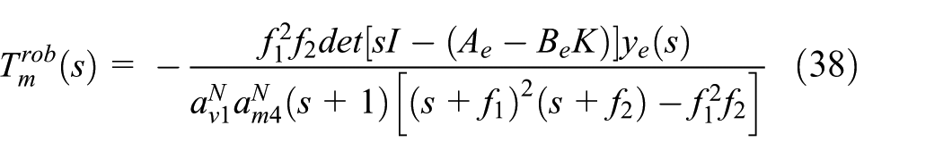
The robust compensator in the frequency domain can be calculated as

Simulations and analysis
In order to verify the effectiveness of the phased compound robust control method based on feedforward–feedback technology and robust compensation approach proposed in this article, a dynamic simulation model of mode transition from EV-to-HEV for the investigated SM-FHEV was established by use of MATLAB/Simulink software, as shown in Figure 10. The model consists of five submodels: HCU, engine model, and engine controller, clutch model, motor controller, and vehicle model. During the mode transition, the HCU sends control command to motor, clutch, and engine separately. When the wet clutch is in slipping state, the clutch model estimates the actual clutch torque Tcle, which is used to cranking engine. When the clutch is locked, it transmits engine output torque to the driveline. The vehicle longitudinal dynamic is determined by the motor torque Tm.

Simulink model of the SM-FHEV for mode transition control.
The nominal values of model parameters for simulation are listed in Table 1. Note that some parameters such as the gross mass, air resistance coefficient, frontal area, rolling resistance coefficient, rolling radius of wheel, and equivalent stiffness of drive axle are provided by Chongqing Changan New Energy Vehicle Company in China. The equivalent inertia of the engine, equivalent inertia of the EM shaft, the total inertia of the wheel and vehicle can be calculated by kinetic energy theory. In addition, the equivalent damping of wheel, equivalent damping of the EM shaft, equivalent damping of the engine are taken from Ye. 20
Parameters for the SM-FHEV.

EM: electric motor.
The parameters of nominal LQR feedback controller, the parameters of robust compensator, and the PID controller parameters are listed in Table 2.
Control parameters.

Nominal simulation
In this section, the simulations with the nominal system model were conducted to evaluate the performance of the proposed four-phase feedforward-LQR feedback nominal controller. All of the model parameters were set to their nominal values, taking into account the nonlinear characteristics of the engine and clutch torques as well as vehicle resistant torque in real applications.
In this study, the filtered Gaussian white noise was applied to imitate the nonlinear
uncertain part of the engine torque, clutch torque, and vehicle resistant torque, which
can be expressed as G(ΔTe),
G(ΔTcl), and
G(ΔTv). Since the nonlinear uncertain
part of low frequency and medium amplitude is focused in this study, the noise bandwidths
for G(ΔTe),
G(ΔTcl), and
G(ΔTv) are set to 20, 40, and 10 Hz,
respectively, and the corresponding noise variances are assumed to be 15, 10, and 30. In
addition, considering the steady error between the estimated torque and the actual torque,
the steady error

where i = v, e, cl.
In this study, a typical increasing vehicle speed profile obtained from the New European Driving Cycle (NEDC) is selected to reflect a typical accelerating process. The vehicle accelerates from 0 to 50 km/h in 25 s (hereafter called case 1), where the EV-to-HEV mode transition occurs.
In order to demonstrate the effectiveness of the proposed four-phase feedforward-LQR feedback nominal controller, a conventional three-phase mode transition control method presented in Liu et al. 6 is utilized to compare with the proposed controller under the same simulation conditions. The conventional three-phase mode transition controller consists of motor torque feedforward compensation control based on constant clutch torque and LQR feedback control. It should be noted that after the engine was ignited, the clutch was still in slipping until the engine and EM speed fully synchronize in the conventional three-phase mode transition control method.
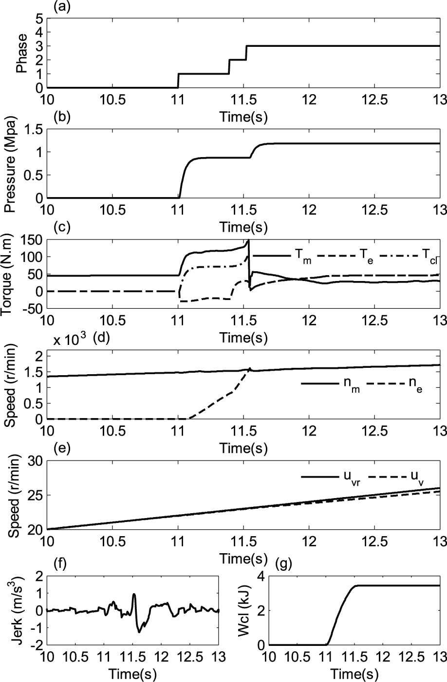
Figure 11 shows the simulation results of EV-to -HEV mode transition using the four-phase feedforward-LQR feedback nominal controller. It can be seen from Figure 11(a) that the whole mode transition is composed of four consecutive phases, corresponding to the engine cranking phase, speed synchronizing phase, clutch engagement phase, and torque coordination phase, which are denoted by the serial numbers 1, 2, 3, and 4, respectively. The clutch pressure; the torques of the engine, EM, and clutch; and the speed of engine and EM during the mode transition are shown in Figure 11(b)–(d), respectively. It can be seen from these figures that the clutch starts to engage at 11 s. As the clutch torque rises, the EM simultaneously provides torque compensation for clutch engagement. The engine starts to rotate at 11.09 s, which indicates that the clutch torque is greater than the engine static resistant torque. After 0.32 s, engine is cranked up to 800 r/min. And then, the clutch is quickly disengaged, the engine starts and accelerates to synchronize with the EM speed. At 11.65 s, the speed difference between engine and EM approaches to the threshold speed, the clutch starts to engage itself again. After the clutch is fully locked, the engine and EM torques are coordinated to their target values until 12.27 s. The mode transition is completed at this time.

Simulation results using the four-phase feedforward-LQR feedback nominal controller: (a) phase; (b) clutch pressure; (c) EM, engine, and clutch torques; (d) EM speed and engine speed; (e) target vehicle speed and actual vehicle speed; (f) vehicle jerk; and (g) clutch frictional loss.
The duration of the mode transition is 1.27 s. The actual vehicle speed tracks the target vehicle speed very well during the mode transition, as illustrated in Figure 11(e). The peak of jerk is 0.898 m/s3 at the slip–stick point, and the clutch frictional loss is 3.08 kJ, as shown in Figure 11(f) and (g).
Figure 12 shows the simulation results of EV-to-HEV mode transition using the conventional three-phase controller. It is clear from Figure 12(a) that the mode transition is divided into three phases, including engine cranking phase, clutch engagement phase, and torque coordination phase, as denoted by the serial numbers 1, 2, and 3, respectively. During the mode transition, the clutch transmits a constant pressure in phase 1 and phase 2, as illustrated in Figure 12(b). The EM simultaneously provides the driving torque and compensates for the clutch torque. When the clutch is locked, the engine and EM torques gradually transition to their target values. The torques of the engine, EM, and clutch and the speed of engine and EM during the mode transition are shown in Figure 12(c) and (d), respectively.
Simulation results using the conventional three-phase controller: (a) phase; (b) clutch pressure; (c) EM, engine, and clutch torques; (d) EM speed and engine speed; (e) target vehicle speed and actual vehicle speed; (f) vehicle jerk; and (g) clutch frictional loss.
The duration of the whole mode transition is 1.21 s. The actual vehicle speed follows the target vehicle speed very well during the mode transition, as shown in Figure 12(e). However, there is a sudden jerk of 1.275 m/s3 at the slip–stick point, and the clutch frictional loss is 3.43 kJ, as shown in Figure 12(f) and (g). Both of which are larger than those values attained by the use of the proposed four-phase nominal controller.
Therefore, it can be concluded that the four-phase nominal controller can achieve better vehicle drivability and minimize clutch wear during the EV-to-HEV mode transition.
In addition, another nominal simulation comparison of EV-to-HEV mode transition under a more sporty condition is also conducted. The vehicle accelerates from 0 to 32 km/h in 12 s (hereafter called case 2), which is also obtained from the NEDC. The simulation results are shown in Figures 13 and 14, respectively. By comparison of Figures 13 and 14, it can be seen that when the proposed four-phase nominal controller is activated, the peak of jerk is 0.793 m/s3 at the slip–stick point, and the clutch frictional loss is 2.75 kJ during the mode transition, as shown in Figure 13(f) and (g), respectively. However, when the conventional three-phase controller is applied, the peak of jerk is 1.55 m/s3 at the slip–stick point, and the clutch frictional loss is 3.02 kJ, as illustrated in Figure 14(f) and (g), respectively. Both the peak of vehicle jerk and the clutch frictional loss using the conventional three-phase controller are larger than those of the four-phase nominal controller.

Simulation results using the four-phase feedforward-LQR feedback nominal controller (a) phase, (b) clutch pressure, (c) EM, engine, and clutch torques, (d) EM speed and engine speed, (e) target vehicle speed and actual vehicle speed, (f) vehicle jerk and (g) clutch frictional loss.

Simulation results using the conventional three-phase controller: (a) phase; (b) clutch pressure; (c) EM, engine, and clutch torques; (d) EM speed and engine speed; (e) target vehicle speed and actual vehicle speed; (f) vehicle jerk; and (g) clutch frictional loss.
The nominal simulation results demonstrate that the proposed four-phase normal controller has better performance than the conventional three-phase controller under a more sporty driving condition.
Simulation with parameter uncertainties
In this section, the mode transition simulation with considering of the nonlinear torque disturbances and model parameter uncertainties is conducted to validate the effectiveness of the four-phase robust compound controller. The nonlinear uncertain part of the engine torque, clutch torque, and vehicle resistant torque is still imitated by the filtered Gaussian white noise, which is mentioned in the previous section. In addition, there are seven parameters (Je, ce, Jm, cm, ks, Jv, and cv) in the dynamic model that may have uncertainties. The nominal values of these parameters are shown in Table 1. In this study, the relative variation of the parameters Je, ce, and ks is set to δ1 = ±10% of the nominal values. The relative variation of the parameters Jv and cv is set to δ2 = ±20% of the nominal values, the relative variation of the parameters Jm and cm is assumed to δ3 = ±30% of the nominal values.
The performance of the four-phase nominal controller is used to compare with the four-phase compound robust controller in the presence of model parameter variation. When the model parameter variation is set to a positive value, the simulation results of EV-to-HEV mode transition under case 1 driving condition are shown in Figures 15 and 16, respectively.

Simulation results with positive model parameter variation using the four-phase compound robust controller: (a) phase; (b) clutch pressure; (c) EM, engine, and clutch torques; (d) EM speed and engine speed; (e) target vehicle speed and actual vehicle speed; (f) vehicle jerk; and (g) clutch frictional loss.

Simulation results with positive model parameter variation using the four-phase nominal controller: (a) phase; (b) clutch pressure; (c) EM, engine, and clutch torques; (d) EM speed and engine speed; (e) target vehicle speed and actual vehicle speed; (f) vehicle jerk; and (g) clutch frictional loss.
Figure 15 shows the simulation results of EV-to-HEV mode transition using the four-phase compound robust controller. It is clear from Figure 15 that the actual vehicle speed tracks the target vehicle speed very well during the mode transition. The peak of vehicle jerk is 0.731 m/s3 at the slip–stick point, and the clutch frictional loss is 3.09 kJ.
Figure 16 shows the simulation results of EV-to-HEV mode transition using the four-phase feedforward-LQR feedback nominal controller. It can be seen from Figure 16 that the peak of vehicle jerk is 0.806 m/s3, and the clutch frictional loss is 3.07 kJ. The peak of vehicle jerk is larger than those result described in Figure 15, while the clutch frictional loss is almost equal to the result in Figure 15. In addition, it can be found that the speed tracking performance in Figure 16(e) is not as good as in Figure 15(e).
When the model parameter variation is set to a negative value, the simulation results are shown in Figures 17 and 18. By comparing Figures 17 and 18, it can be found that both the peak of vehicle jerk and the clutch frictional loss in Figure 17 are smaller than those results described in Figure 18. And the speed tracking performance in Figure 17(e) is much better than the result in Figure 18(e).

Simulation results with negative model parameter variation using the four-phase compound robust controller: (a) phase; (b) clutch pressure; (c) EM, engine, and clutch torques; (d) EM speed and engine speed; (e) target vehicle speed and actual vehicle speed; (f) vehicle jerk; and (g) clutch frictional loss.

Simulation results with negative model parameter variation using the four-phase nominal controller: (a) phase; (b) clutch pressure; (c) EM, engine, and clutch torques; (d) EM speed and engine speed; (e) target vehicle speed and actual vehicle speed; (f) vehicle jerk; and (g) clutch frictional loss.
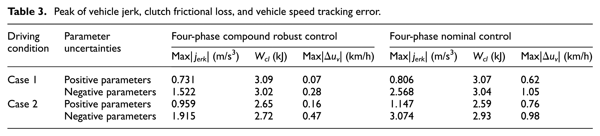
The peak of vehicle jerk |Jerk|, clutch frictional loss Wcl, and the maximum vehicle speed tracking error Δuv during the EV-to-HEV mode transition under case 1 and case 2 driving conditions are shown in Table 3. It can be seen from Table 3 that using the four-phase compound robust controller, the SM-FHEV has smaller vehicle jerk, less clutch frictional loss, and better vehicle speed tracking performance during the EV-to-HEV mode transition. The results indicate that four-phase compound robust controller is able to guarantee sufficient performance even in the presence of torque disturbances and parameter uncertainties.
Peak of vehicle jerk, clutch frictional loss, and vehicle speed tracking error.
Conclusion
In this study, a novel four-phase compound robust control method was proposed to address the issues of vehicle drivability and excessive clutch wear during the EV-to-HEV mode transition for the SM-FHEV. The following three points can be concluded from this study:
The EV-to-HEV mode transition process was divided into four consecutive phases according to the operating status of engine and clutch.
In each phase, considering the effects of the various nonlinear torques and system parameter uncertainties, the system model was rewritten as a linear model with equivalent disturbances. The equivalent disturbances include the nonlinear uncertain part of the engine/clutch torque and the vehicle resistant torque as well as the model parameter uncertainties. The four-phase feedforward-LQR feedback controller was designed for the nominal linear plant to guarantee a desired control performance, and the robust compensator was added to restrain the equivalent disturbances.
Moreover, in the speed synchronization phase, the engine adopts a feedforward-PI feedback controller to regulate engine speed synchronization with the motor speed, while the clutch is disengaged to reduce the wear of clutch.
Simulations were conducted to verify the effectiveness of the proposed control method. The results demonstrate that the four-phase compound robust control method can achieve better vehicle drivability and minimize clutch wear during the EV-to-HEV mode transition even in the presence of various torque disturbances and parameter uncertainties.
Footnotes
Academic Editor: ZW Zhong
Declaration of conflicting interests
The author(s) declared no potential conflicts of interest with respect to the research, authorship, and/or publication of this article.
Funding
The author(s) disclosed receipt of the following financial support for the research, authorship, and/or publication of this article: This work was supported by the Key Scientific Research Fund of Xihua University (project no. z1420307), the Youth Science and Technology Innovation Team of Sichuan Province (project no. 2015TD0021), and the National Natural Science Foundation of China (project no. 51575063).