
Abstract
Energy saving is important for the underwater gliders because they have limited onboard battery power. A novel optimal three-dimensional path planning method is introduced in this article, which has low energy consumption and is useful for the path planning of underwater gliders. The method is derived using optimization theory. In the planning process, the constrained control does not pass the zero point to obtain the turning path formed by the unidirectional arc. Then, the method is extended to three dimensions, which includes depth parameter. For the more complicated median-depth path, glider’s glide distance is increased by extending the turning radius, in order to achieve the end state. Compared with the traditional three-dimensional Dubins path, the simulation results indicated that the proposed optimal path leads to the glide with a lower energy consumption.
Introduction
Underwater glider is a type of buoyancy-driven, fixed wings underwater vehicle. It can run a long time in the water, sampling and detecting in certain water area. 1 The capability of long running time and low energy consumption is essential to achieve the set task in a large area. To reduce energy consumption and improve running range by reasonable planning of the movement and glide path, the low-energy motion control of the glider is generally achieved by reducing the operating frequency of the glider’s actuators and the operating time of the control system.2,3 The glider paths’ type needs to be considered in the path planning.
The steady glide path of the glider includes the zigzag movement in the longitudinal plane and the spiraling movement in the three-dimensional (3D) space. 4 The path length of the glider is long in the longitudinal plane, and the boundary condition of the path planning is mainly from the environment.5,6 A glider needs steering movement when adjusting its heading or performing a special task. Energy consumption and steering time need to be considered in the path planning of the movement. Excessive heading adjustment method will waste energy and time; meanwhile, a great 3D path planning for glider can further reduce energy consumption. An optimal turning path planning method for underwater gliders is presented in this article.
Dubins paths are the shortest path between two oriented points, which contain arc segments of minimum turning radius and straight-line segment. 7 Dubins paths are obtained based on geometrical methods in accordance with the optimization principle. Based on Pontryagin’s minimum principle (PMP), the optimum of Dubins paths is validated, and the form of path and the position of trajectory transformation point are fully explained using the singular arc theory. 8 Dubins paths have been widely used in the shortest path planning on many kinds of vehicles.9–12 Dubins paths are also applied on underwater gliders. Mahmoudian et al. 13 planned an underwater Dubins path especially for gliders by taking into account the control rate limit. Cao et al. 14 planned a glider energy optimization 3D Dubins path of the glider by considering the energy consumption of the executive parts. When the glider gliding in a steady state, it no longer consumes energy and is able to move continuously. This character is different from wheel-type robots and aircraft which need continuous driving. For which, the shortest path is the optimal path of energy consumption. The glider has steady state glide characteristics, which are similar to those of satellites. The optimal Hohmann orbit method for satellite fuels only requires the actuator to act twice. 15 Unlike the satellite’s unidirectional orbit, the glider’s turning orbit has two directions, either clockwise or counter-clockwise. It consumes more energy to ensure the control of orbit transfer between two different rotational directions in one control period. Referring the form of the satellite orbit, the position of the glider’s turning actuator is constrained so that the glider’s steering orbits are co-steered during a complete control period.
The dynamics model of underwater glider is the basis of motion analysis, and the model is a typical multi-body dynamics system, which adjusts the body posture by means of internal actuators rigidly connected to the hull. Leonard and Graver 16 first modeled a glider dynamics based on classical mechanic method. Considering the different driving modes, a variety of dynamics models of glider can be obtained.17–19 The 3D dynamic equations of underwater gliders are nonlinear, and the variety and the quality of the parameter increase its difficulty of gaining the solution. Mahmoudian 20 used the perturbation theory to obtain the analytical solution of steady state glide. Cao et al. 21 obtained the approximate semi-analytical solution by simplifying dynamic equations. Zhang et al. 17 proposed an iterative logic to obtain steady state solutions. Fan and Woolsey 22 used the Trust-region-dogleg to obtain numerical solution. In this study, the particle swarm optimization (PSO) algorithm is used to obtain the solution which can avoid to get a local optimal solution.
In this study, the optimal path of the glider is proved with PMP theory, and the construction method of the path is given. As the two-dimensional (2D) path is extended to the 3D space, the depth of the path needs to be considered. 23 The proposed path is extended to 3D space, and the application under different depths is investigated.
Optimal path of underwater glider
Model description
Consider a glider that moves in an inertial, horizontal plane at a unit constant forward speed and in some direction relative to a reference frame fixed in the plane. The glider performs a straight-line motion when the turn actuator of the underwater glider is at natural zero point, and the glider performs a turning motion when the turn actuator is on non-zero position. If the glider moves in the Dubins paths, which contain two arc segments of minimum turning radius, more energy is needed, and it is a disadvantage for glider’s endurance capacity.
For a further energy saving, the rotary actuator of the glider is limited only to move on one side of the zero position in one control period. In other words, in this study, the rotary actuator’s movement range is

Underwater glider coordinate system.
The above constructions on the control indicate that the heading rate is always greater than zero or constant less than zero in a control period. The rotation period of the rotating mechanism is very small compared with the glider’s turning period. Therefore, in this study, the limitation of the control rate is neglected, and the action of the rotating mechanism can be completed instantaneously.
The kinematic model of the underwater glider includes the glide angle and the roll angle in a form similar to the kinematics of the aircraft. In order to simplify the analysis, in the discussion of this article, the kinematic model of the aircraft is used to express the motion of the glider 24

where V is glide speed,
Optimal path of underwater glider
In 2D case, when the glide angle is 0°, the depth is not included in the equation of motion, and the heading rate is chosen as the control variable. The kinematics equation can be simplified from equation (1) as

where u is the offset of gliders’ turning actuator respect to the zero point, and k is a constant.
Set the unit glide speed. According to the optimization principle, the shortest path problem for a glider can be described as

Control constraint means that the glider can only turn in one direction during a control period. Based on the PMP, the Hamiltonian function of the system is

The adjoint system is

To minimize equation (4), have

Therefore, the minimum value of the above equation depends on the sign of

When
From the above analysis, the optimal turning motion control of the underwater glider is the bang–bang control problem. The paths consist only of the maximum and minimum turning radius arc, which converts state between two arcs at most one time in one control period. An underwater glider moves at minimum turning radius when
From the above discussion, only six forms of path may be obtained, which are
Geometric construction of optimal path
The shortest path of the underwater glider consists of two arcs of different turning radii. According to the Dubins paths construction method, set the initial and final states as
Step 1. Determine the state vector. From the given data, find the position vectors r and the velocity vectors V.
Step 2. Determine the minimum turning radius circle. Drawing two circles with minimum turning radius tangent to the velocity vector V at each end point, respectively, thus four circles
Step 3. Determine the maximum turning radius curve. As previously discussed, the path between the end points is composed of at most two kinds of arcs with different turning radii. Drawing a large circular arc tangent to the two circles selected in step 2 from either end point, the two circles are connected by the large arc. The connected two circles of minimum radius tangent to vector V for each end point in step 2 should be on the same side of each V to ensure the continuity. That is only one circle for each end point is selected. For example, circles
Step 4. Determine the optimum path. Comparing all the available paths, the path 2 is shorter, and it is selected as the optimum path.

Construction of optimal path of gliders.
The glider optimal path is longer than the Dubins paths because the straight-line segment is no longer included. As shown in Figure 3, path 2, labeled blue in the figure, is the glider optimal path and path 3, labeled green, is Dubins path.

Glider optimal path and Dubins path: path 2 is glider optimal path (blue) and path 3 is Dubins path (green).
The Dubins paths require that the distance between the starting point and the end point more than twice longer than the turning radius. Likewise, the application conditions of the glider optimal path proposed in this article are that the distance between the starting point and the ending point is more than twice longer than the turning radius.
Optimal path in 3D space
Because it contains information such as depth and glide angle, the motion path in 3D case is more complicated than in 2D case. Following M Owen and RW Beard, gliders’ glide depth is divided into three types: low depth, median depth, and high depth. 25 The three cases are briefly described as below.
The depth between the start and end point is said to be low depth, if
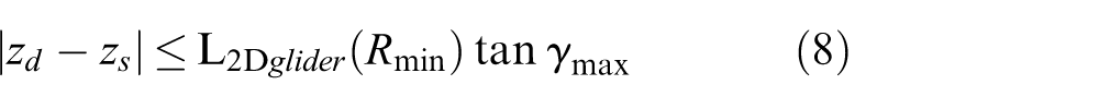
where

The depth is said to be high depth, if

Low-depth glider path
At low depth, the glider can reach its target at an unsaturated glide angle. The Hamiltonian function of equation (1) can be constructed as

where

The control law on the optimal path is
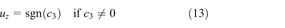
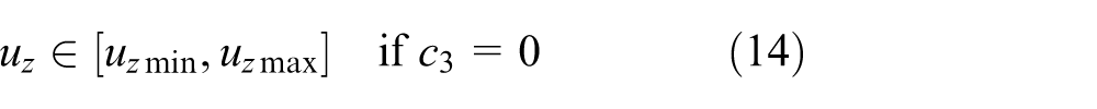

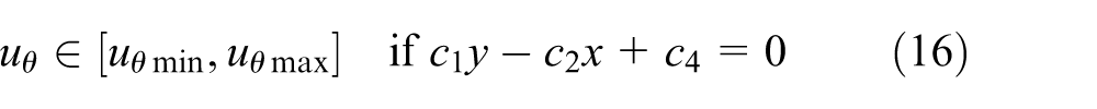
According to equation (14),

The optimal glide path length is

High-depth glider path
At high depth, the Dubins paths are too short to reach the target, and the path needs to be extended to the end by increasing the helical path. Corresponding to

and
where

The length of path is
Median-depth glider path
In the median-depth case, the Dubins paths are not sufficient to reach the target; if one spiral is added, the path is too long. Now, the path is extended to the end by extending the path. Owen and Beard extended the path by increasing the arc path. However, for gliders, another added arc means the glider needs to transfer orbit twice, and the actuator needs to move twice, which is not conducive to gliders’ endurance. In this article, the path is extent by increasing the minimum turning radius. The radius of turn after the increase is

The path length is

Case study
In this section, numerical analysis for the above three depth cases are studied.
For the three cases, set the minimum turning radius of the vehicle to 20 m, and in the north–east coordinate system, the initial point coordinates and direction were (20, 60) m and 10° north east, respectively. The terminal point coordinates and direction were (250, 250) m and 171° north east, respectively.
For the low-depth case, set the initial and terminal depths as −20 m and −70 m, respectively. The numerical results show that the maximum turning radius is 377.72 m, the optimal path length is 343.85 m, the glide angle is −8.27°, and the 3D path length is 347.46 m. The result path is shown in Figure 4, in which the green square marks the starting point and the red circle marks the ending point.

Low-depth glider paths.
For the high-depth case, set the initial and terminal depths as −20 and −1500, respectively. The iterative numerical results show that the minimum turning radius after fine tuning is 20.3 m, and the maximum turning radius is 379.27 m. The 2D optimization path length is 344.37 m, moving at the maximum glide angle of −60°. At the end of the path, four complete spiral movements are added to the terminal point, and the length of 3D path is 1709.10 m. The path is shown in Figure 5.

High-depth glider paths.
For the median-depth case, set the initial and terminal depths as −20 and −700, respectively. The iterative numerical calculation shows that the minimum turning radius after adjustment is 45.05 m, the maximum turning radius is 616.72 m, the length of optimal 2D path is 392.48 m, the glide angle of −60°, and the length of optimal 3D path is 784.97 m. The path is shown in Figure 6.

Median-depth gliding paths.
Simulation and discussion
In this section, the optimal method used on underwater glider is discussed based on the analysis above.
Steady state solution
The dynamic equation of the underwater glider includes nine parameters. Generally, parameters such as speed, glide angle, and heading rate are given to obtain the parameters as pitch angle, axial position of the slider, slide angle, angle of the actuator, body roll angle, and net buoyancy.
In this study, thermal Slocum glider is the research object, which is roll-yaw inverse coupling, during the downward gliding, the glider moves clockwise with the maximum turning rate around the z-axis when the turning actuator move about the x-axis to the clockwise largest position; otherwise, the glider will rotate anti-clockwise around the z-axis with the maximum turning rate. Parameters are defined as the same as in the literature. 4 The steady state gliding dynamic model is shown in Appendix 1.
The minimum turning radius of the Slocum was set to 20 m, and in the north–east coordinate system, the coordinates and direction of initial point were set to (20, 60, −20) m and 10° north east, respectively. The coordinates and direction of terminal point were set to (250, 250, −100) m and 171°north east, respectively. The iterative numerical calculation shows that the maximum turning radius is 377.72 m, the length of optimal 2D path is 343.85 m, the glide angle is −13.0975°, and the length of optimal 3D path is 353.03 m. The glide speed was set at 0.725 m/s and the angle of attack was set at 4.3°, in which configuration the glider reaching the maximum lift-to-drag ratio. When glider spirals, its parameters such as the speed, yaw rate, and turning radius need to satisfy the following equation
where
Set
As shown in Table 1, due to the coupling of the dynamic parameters, there are slight differences in
Underwater glider steady state solution in different heading rates.

Result analysis
As shown in Figure 7, the solid curve is the optimal path proposed in this article, and the glider is initially gliding at a straight line with no roll angle. First, the actuator rotates −1.1768° and glided 308.81 m by the turning radius of 377.72 m, then, rotates −22.3789° to −23.5557° and glided 44.22 m by the turning radius of 20 m, and finally, back to initial zero position by rotate 23.5557°. The total rotation angle of the actuator is 47.1114° and the total path length is 353.03 m. The dashed curve is the 3D Dubins path. At the beginning of the path, the actuator rotates −23.5557°, glided 12.54 m by 20-m turning radius, then, rotates 23.5557° to reach the straight-line state and glided 227.41 m, then, the actuator rotates −23.5557°, glided 44.20 m by 20-m turning radius. To achieve the end state, the rotary actuator rotation 23.5557° back to zero initial position. In the path, the total rotation angle of the actuator is 94.2228°, and the total path length is 334.15 m.
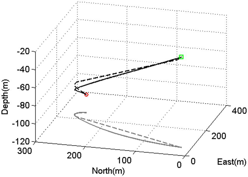
Comparison between optimal glider path and 3D Dubins path: the solid line curve is the optimal path
The path energy consumption was set as

where
The energy consumption of the Dubins car path is not always greater than the energy consumption of the optimal glider path. The energy consumption of Dubins car path is larger, mainly because of the movement of the actuator is more frequent. For typical Dubins car path consisting of two arcs and one straight line, the actuator executes four times in the path. For the proposed optimal glider path, the actuator executes two times in the path. When the length of the Dubins car path is less than half the length of the optimal glider path, the energy consumption of the Dubins car path will be smaller.
Conclusion
This article presents an optimal path planning method for underwater glider based on Dubins paths. The optimal path can be optimized by adjusting some restrictions based on optimization theory. The path can be composed by the maximum and the minimum turning radius arcs by constraint actuator’s movement position. The proposed method can be extended to a 3D space containing depth parameters. For the complex median-depth path, the method of extending the turning radius can effectively increase the gliding distance of the glider, so as to obtain the path optimization method to construct the shortest path. The application of the optimal path to the underwater glider is studied. And the results indicated that it has a lower energy consumption rate compared with the traditional 3D Dubins path.
Footnotes
Appendix 1
The 6-degree-of-freedom (DOF) steady state gliding dynamic equation of underwater glider
The meaning of each parameter is shown in Table 2.
The definition of the above coordinate system is the same as in Wang et al. 18 To solve the steady state solution of the above equations, the left side of the equals sign is zero. Get the solutions by least square form of evaluation function
When
Academic Editor: Haiping Du
Declaration of conflicting interests
The author(s) declared no potential conflicts of interest with respect to the research, authorship, and/or publication of this article.
Funding
The author(s) received no financial support for the research, authorship, and/or publication of this article.