
Abstract
A machine-vision method was used to build a three-dimensional measurement system using a measurement algorithm and a perspective transformation. The image data from a double complementary metal oxide semiconductor were transmitted to a notebook personal computer to calculate the parameters. A three-dimensional measurement system for obtaining its feature points in the world coordinate system was used to calculate the measurement data. The experimental results were verified with a more precise measurement equipment, automatic transformer observation system. The three-dimensional measurement system introduced here was applied to two case studies. The first case considered the measurement of hole diameters, such as those found in the cylinder head of an internal combustion engine. By summarizing various experimental results based on studies of three kinds of hole designs, the maximum error was 0.373 mm and the minimum error was 0.053 mm, which is within the general range of manufacturing tolerances (±0.5 mm) used in engineering schematics. The second case examined the measurement of certain key dimensions of an aggregate truck bed, and the results showed that the measured difference between the three-dimensional method and automatic transformer observation system is less than 1.2%. The proposed three-dimensional measurement system is inexpensive, offers an easy set up, and provides a certain amount of accuracy and stability.
Introduction
With the rapidly growing demand for industrial automation in the manufacturing sector, machine vision now plays an important role in many fields. Machine-vision technology is quickly becoming a widely applied measurement method toward the quality inspection of a wide variety of products. Geometric and size measurements are among the essential quality control processes that are performed to ensure that manufactured parts conform to specified standards in mechanical engineering. This type of inspection is normally done through the use of specialized instruments, such as a steel rule, micrometer, inside micrometer, vernier caliper, coordinate measuring machine (CMM), which all require direct physical contact. The advantages of a contact measurement are found in the high measurement accuracy and the general suitability for basic quantitative geometries. However, most contact measurement methods are usually limited by the size of the analysis and the high cost involved with time-consuming skilled labor. These drawbacks may be overcome by implementing a non-contact measurement method, such as the use of laser measurement devices, ultrasonic measurement methods, machine-vision systems, automatic transformer observation system (ATOS) scanning measurement equipment.
The machine-vision method is based on the human visual system which can detect the dimensions of objects by means of light passing through an individual’s cornea, pupil, and lens and then projecting images onto the retina. Then, the visual signals received through the optic nerve can pass into the brain. The analysis and integration within the brain can ascertain depth perception of those objects. The stereoscopic vision system of the human body can thereby determine the relative and absolute distance of observed objects, and even the thickness of the objects, as well as other features. A machine-vision system is analogous to the function of the human eye in that the complementary metal oxide semiconductor (CMOS)/charge coupled devices (CCDs) inside the cameras are comparable to the human eye’s cornea, pupil, and lens. The lens aperture in a machine-vision camera is approximately the same as a human pupil, in that they both regulate the amount of light received, and the CMOS/CCD internal sensors (image sensors) are equivalent to the retina of the human eye. With the machine-vision method, the visual information is transmitted to a personal computer (PC) through the signal line of a mainframe computer, and then the spatial position of the object to be measured; it is calculated according to its location in the world coordinate system. 1 A machine-vision system generally consists of five basic components: a light source, an image capturing device, an image capturing board (frame grabber), and an appropriate computer hardware and software system.
In recent years, many authors have studied using machine vision in many fields, such as agriculture, manufacturing, and medical-related sciences. For instance, Chen et al. 2 showed that machine vision can provide a non-contact measurement inspection process for measuring a wide class of objects. Kumar et al. 3 used machine vision to evaluate the surface roughness in manufacturing. With this method, they obtained a good linear relationship between the average surface roughness (Ra), and the average gray level (Ga), with a high level of accuracy. In addition, machine vision has been used to control the quality of products, for example, in estimating classifications of surface roughness, 4 and in measuring hot-formed products. 5 In agriculture, it has been used to detect defective eggs and fruit, as well as plant diseases. 6
Within machine-vision technology, the performance largely depends on calibration accuracy. Karaszewski et al. 7 presented a novel system for a three-dimensional (3D) digitization of cultural heritage objects, which allowed a completely automated shape measurement. The system was used for the digitization of a whole museum collection. An algorithm for the next best view calculation was presented, which contained an application that calculated the inverse kinematics and determined a collision-free path for the measurement probe to reach the next measurement position. Ivo et al. 8 proposed a robust 3D scanner based on structured light. Volumetric parameters of both an artificial object and a human body segment were obtained through 3D scanning. The analysis of large-scale scanning techniques using a laser scanner was investigated by Wang et al., 9 who performed both point measurements and surface measurements to minimize errors, and these values were used to calculate the uncertainty. The measurement deviation and the statistical values of variance were determined by Palousek et al. 10 for a 3D digitizing process of glossy surfaces coated with a titanium oxide coating or a chalk powder spray. A 3D optical scanner, ATOS III Triple Scan, was used for capturing and evaluating the data, which revealed a significant difference between the chalk and titanium matte coatings. C Lin et al. 11 proposed a novel 3D alignment method based on two-dimensional (2D) local feature matching. Their proposed method converted the point clouds into 2D bearing angle images and then used the 2D image-based matching method, SURF, to find the matching pixel pairs of the two images. Y Ji et al. 12 presented a novel design for an automatic and complete parameter calibration system, using information from a 3D texture map to construct an intelligent space data-acquisition method for camera sensor networks.
In this article, machine vision is used to establish a non-contact 3D measurement system using a measurement algorithm and a perspective transformation method. Double CMOS cameras are used to capture the images of the objects. A real pattern is used to calibrate the coordinates. After capturing the images of the objects and calibrating the camera, a linear transformation between the image coordinate system and the world coordinate system is performed, thereby determining the real-world dimensions of the objects. Two case studies are investigated as examples of this application process. The first case involves measuring the diameters of holes, such as those found in the cylinder head of an internal combustion engine, and the second case refers to measuring certain key dimensions of an aggregate truck bed, as is typical in construction and mining. The results are then compared with the results of other contact measuring methods and are further verified by more precise instruments, ATOS and CMM.
Research methodology
Stereo imaging
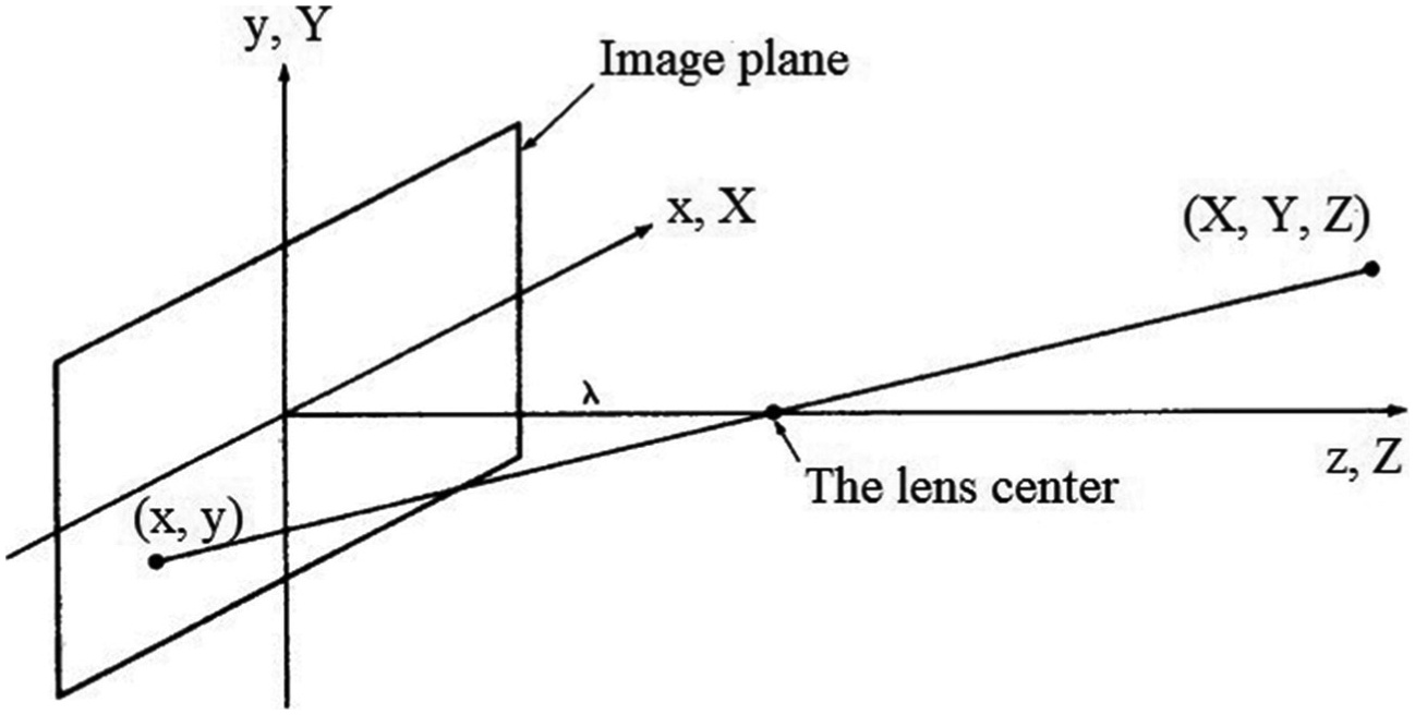
Two coordinates (x, y) are needed to represent a point on a 2D image plane, whereas in space, a point is specified by three coordinates (X, Y, and Z). The difference between an image plane and a stereoscopic visual is that the image plane cannot interpret the 3D coordinate information of objects, while the stereoscopic visual can. Thus, when a 3D scene is mapped onto an image plane, one dimension is lost, as it cannot identify a unique point corresponding to a position in space within a 3D field of perspective. Specifically, the depth information (along the Z-axis) in the 3D perspective projection is omitted from the photographed 2D image. Therefore, one of the important goals of the present machine-vision method is to recover this lost dimension in order to fulfill the purposes of the non-contact 3D measurement.
To solve the problem described above, stereo imaging is utilized. Stereo imaging involves obtaining two separate 2D image viewpoints of a 3D object in space, similar to how humans receive two slightly different images through two eyes. The goal of stereo imaging is to find the world coordinates (X, Y, and Z) of any point featured on the surface of an object, by combining the information about this image point from the two image planes within the left and right cameras. An inspection of the system, as shown in Figures 1 and 2, reveals that the lens center and the feature points are on a straight line known as a baseline, which represents the path of optical light transmission. The baselines go through the lenses of the two cameras and intersect at a feature point on the surface of the object. By changing the orientation of the baselines, it is possible to obtain multiple feature points of an object through the lens center, without changing the camera’s direction or relative position. Because the lens serves as a central point of baseline rotation, different feature points on the object can be coordinated with unique points on the image produced within the camera. The image data collected from the stereo-vision are used to calculate the missing dimension using the transformation algorithms. As a result, the 3D coordinates of the feature points can be determined and the geometry of the object can be digitally reconstructed. The stereo-vision diagram, the position of the lens center, and the image coordinates for feature points on the surface of an object are shown in Figure 1. Here, A and B are considered to be the two image points, respective to the left and right image planes.

The schematic diagram of a stereo-imaging system.
The specific perspective projection model. 13
The generalized perspective transformation
Whenever an image of a real 3D object is projected onto a 2D plane, the perspective transformation plays an important role in the machine vision. This work adopts a concept of optical projection known as the pinhole camera, or the pinhole projection method. Here, the camera is regarded as a pinhole, in the same way that light from an image is projected through a pinhole onto an image plane. The lens center is assumed to be a single point. The basic schematic model of the imaging process is shown in Figure 2. The Z-axis and origin coincide with the optical axis and optical center of the camera lens, respectively. The center of the image is at the origin and the lens center is at the coordinates (0, 0, and λ), where λ is the focal length, or the distance between the lens and the image plane. Normally, the coordinate system of the camera’s image plane is not properly aligned within the world coordinate system, and so a generalized perspective transformation is needed. The world coordinates (X, Y, and Z) are transformed into the camera coordinates (x, y), with respect to the projection. Figure 3 shows the generalized perspective projection model of a point in 3D perspective, defined in the world coordinate system (X, Y, and Z), and named wh, onto an image plane with the coordinates (x, y, and z), named ch.
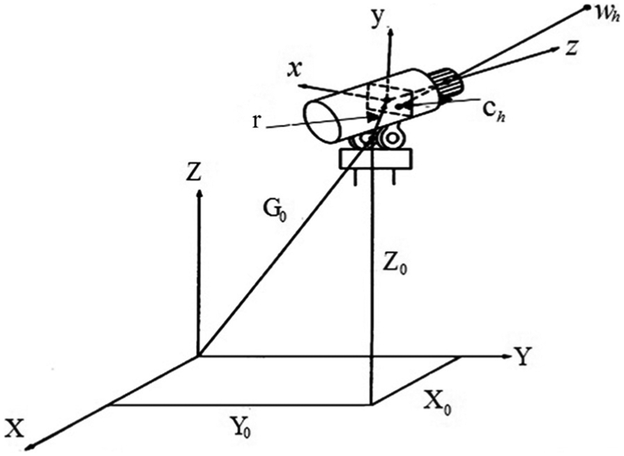
The generalized perspective projection model. 13
To begin with, a camera is mounted on a rotating shaft. The lens center is set at the coordinates (0, 0, and λ). The center of the base of the camera mounting shaft is at G0 (X0, Y0, and Z0) and is located at some distance from the origin of the world coordinate system. The center of the camera’s image plane deviates from the axis of the shaft and is denoted by the vector r, with the components, r1, r2, and r3. θ is the angle between the x-axis of the camera’s image plane and the X-axis of the world coordinate system, and α is the angle between the z-axis of the camera’s image plane and the Z-axis of the world coordinate system. θ and α are used to form a rotation matrix (R), which is used in the conversion. Here, ch is the camera coordinate, wh is the world coordinate, C and G are translation matrices, and P is a perspective specific transformation matrix. A generalized perspective transformation involving the two coordinate systems can now be expressed, as given in equation (1)

The PCRG component of the equation can be condensed into a single generalized perspective transformation matrix, T, and is therefore expressed by equation (2). The projection coordinates (x, y) can be obtained through equation (3)
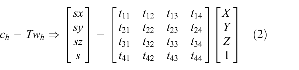

The T matrix includes 16 unknown parameters, but four parameters (t31, t32, t33, and t34) are not necessary for the calculation process, and are therefore ignored. So, we only need to find 12 parameters, which are tij (i = 1, 2, 4; j = 1,…, 4). From equation (2), we can form a mathematical relationship between the coordinates of the points in the image plane and the coordinates of points in the world coordinate system, as shown in equation (3). To find these 12 parameters, six calibration points in the world coordinate system are used. 14 These points correspond to the image points in each image plane. After these 12 parameters are determined, tij (i = 1, 2, 4; j = 1,…, 4), they are substituted into equation (3) to reconstruct the world coordinates. As yet, there are still three unknown variables (X, Y, and Z) remaining in equation (3), but with only two equations, a solution cannot be found. The missing information corresponds to the depth perspective, which is lost in the 2D projection.
To solve this problem, we take into account that two cameras are used, with each one contributing a set of data. With double cameras, we have two image planes: the left image plane and the right image plane. Six points on the sample are found on the left image plane, and six similar points on the right plane. When the camera calibration is completed, the spatial coordinates of the feature point will be obtained from two projections of the same scene taken from different perspectives, and the feature point can then be found in the world coordinate system. 14 In equation (4), superscript (1) represents the left image plane, and superscript (2) represents the right image plane

Experimental setup
The non-contact measurement system
The non-contact measurement system consists of a laptop with appropriate data processing software installed for the coordinate transformation, a calibration sample, and a double CMOS camera for the purpose of recording the images. The specifications of the CMOS cameras are described in Table 1. First, a double CMOS camera is mounted at two different positions. In order to measure the depth of a point, the point must be visible to both cameras, and the point must also be identifiable in both images according to the world coordinate system, as shown in Figure 4. In order to perform the conversion between the image coordinate system and the world coordinate system, the measurement system needs to determine six calibration points on each image plane of the sample, corresponding to the image coordinates. In measurement processing, the positions of the two cameras should not be changed. Therefore, the object to be measured should be interchanged with the calibration sample, in full view of the camera setup.
Specifications of the CMOS cameras.

CMOS: complementary metal oxide semiconductor; LED: light-emitting diode.

Basic components of the 3D measurement system.
Next, the coordinate values of the six calibration points in the world coordinate system are entered into the measurement system. Using the known world coordinates of the six calibration points, and the six calibration points projected onto each of the two image planes, the conversion between the world coordinate system and the image coordinate system may then be performed in the 3D measurement system, as shown in Figure 5.
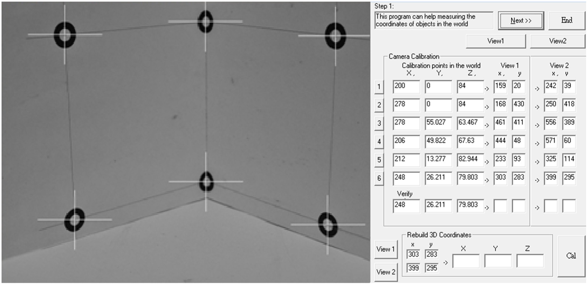
Interface of the 3D measurement software.
Camera setup and calibration
The cameras used in this study were identical, and the locations of the cameras were tested in order to obtain a suitable position for both the height and angle in relation to the object. Although the location of each camera’s origin was different, the coordinate systems of the two cameras were perfectly aligned.
In order to achieve the stereoscopic measurement required, it was first necessary to calibrate the camera. The purpose of the camera calibration was to improve the transformation results, which were, in this case, based on the coordinate measurements, rather than using a known transformation to map the coordinates from one coordinate system to another.15,16 The calibration was also used to construct the projection model that relates the two coordinate systems, and to identify the relative camera parameters, which include both internal and external parameters.
The internal camera parameters describe the camera coordinate system containing the projected image, following the pinhole model. Here, the camera is considered to be an integral part of the image formation, and so the parameters are characterized by the geometrical optics unique to the camera. The internal camera parameters are usually unknown, so manufacturers are not able to provide the relevant information. Thus, only using camera image correction technology, the necessary internal parameters of the camera can be obtained.
The external camera parameters pertain to the camera position and the absolute spatial coordinates between the two cameras. The camera’s coordinate systems and the transformation parameters between the coordinate systems include a rotation matrix, along with a parallel displacement matrix (a translation matrix). Here, it should be noted that θ and α are used to relate the image plane of each camera to the origin of the world coordinate system, and so each camera will have different values of θ and α.
Due to the effects of the focal length and light intensity factors, the two cameras must first be adjusted to the position and angle of the light source in order to obtain the appropriate brightness level. In doing so, a mobile or brightness adjustable light source apparatus may prove useful, in order to avoid moving the locations of the cameras later on. After the image of the pattern is clear, then the cameras should be calibrated before the image is captured. If the location of the workpiece should be moved, then both cameras will need to be recalibrated again.
Results and discussion
Case study 1: hole diameter measurements
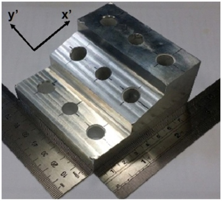
The first case study dealt with measuring the diameter of a hole, such as those typically found in the cylinder head of an internal combustion engine, as shown in Figure 6. Of note, these holes are oriented with the central axis normal to the surface plane. In this section, four measurement methods were used, including CMM, ATOS, a manual measurement using an inside micrometer, and the machine-vision measurement system using the double CMOS cameras. Three types of holes were verified: a drilled hole, which has a 90° edge, a post or guide-pin hole, which has a chamfered edge with a conical surface, and a counter bored hole, which is commonly used to sink cap screws. The positions of the holes were located on three separate planes, with one plane being inclined at 20°, as shown in Figures 7 and 8. The measured diameters of nine holes, using the four methods mentioned, were compared together, along with the errors. For the chamfered and counter bored holes, the outer edge was measured, and not the internal diameter of the hole. Here, the test object is not considered to be reflective. It was painted with white paint on its surface, having an average thickness ranging between 0.022 and 0.05 mm.
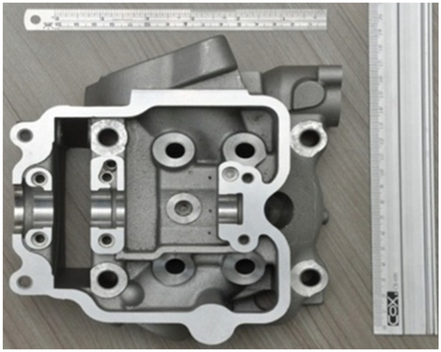
The cylinder head of an engine, containing various holes.
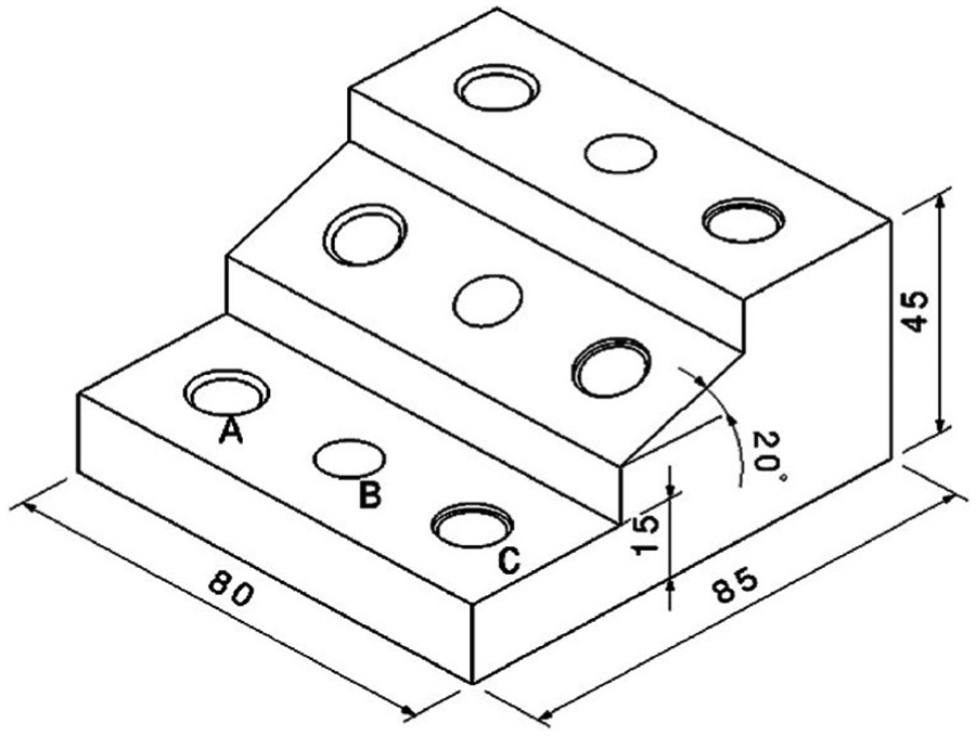
The CAD schematic of an entity sample.
The entity sample of a cylinder head with various holes.
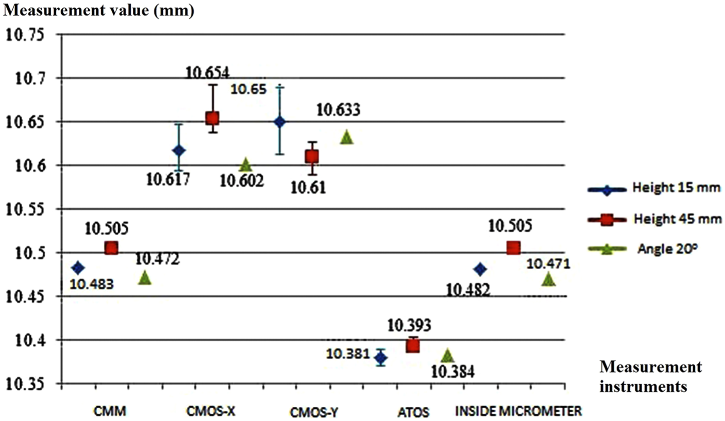
The whisker charts, displayed in Figures 9–11, show a comparison of the measured results for the drilled hole, the counter bored hole, and the chamfered hole, respectively, using the four measurement methods. The present machine-vision results are shown as CMOS-X and CMOS-Y, which are the measured diameters along the x′- and y′-directions, respectively, as indicated in Figure 8.
The whisker chart showing the measured diameters for the drilled holes, using four measurement instruments.

The whisker chart showing the measured diameters for the counter bored holes, using four measurement instruments.

The whisker chart showing the measured diameters for the chamfered holes, using four measurement instruments.
The maximum error displayed by the ATOS scanning measurement system was 0.147 mm, and the minimum error was 0.057 mm. The maximum error of the machine-vision method using the dual-CMOS camera system was 0.373 mm, and the minimum error was 0.053 mm. The maximum positive deviation was 0.041 mm and the minimum positive deviation was 0.014 mm. The maximum negative deviation was 0.039 mm and the minimum negative deviation was 0.014 mm.
Concerning the drilled holes and the counter bored holes, the ATOS scanning measurement system had the greatest precision among all the methods. The CMM and the inside micrometer had the least deviation for these two types of holes, followed by the ATOS method. For the drilled holes, the CMM method was the most accurate.
For the chamfered hole, Figure 11 shows that the ATOS method had the least deviation, followed by the 3D measurement system. With normal surfaces, the CMM equipment and the inside micrometer are the easiest tools available to measure objects with great accuracy. However, when measuring the diameter of the holes with the conical chamfered surface, a technical difficulty arose when using either the CMM or the inside micrometer, leading to these methods having the greatest measurement error. For the CMM, the error occurred because the spherical electron probe could only move along the X-, Y-, and Z-axes, whereas for the micrometer, it was difficult to place the jaws precisely on the tip of the obtuse edge during the measurement process.
Case study 2: aggregate truck bed measurements
The second case study investigates measuring the dimensions of an aggregate truck bed. In Figure 12, L1, L2,…, L6 and R1, R2,…, R7 are considered to be key feature points, and these were chosen for the measurement study. Here, only the 3D machine-vision method and the ATOS method were applied, and the results of the measured data are compared to each other in Table 2. The results showed that the maximum error is 1.2% and the minimum error is 0.032%. Moreover, the 3D measurement system can be used to measure the sizes of objects for which the allowable error is under 2%. These data may then be used with a suitable software in subsequent calculations to estimate the volume.

The aggregate truck bed model, showing the key feature points.
The measured distances between two feature points within the Y (horizontal) and Z (vertical) world coordinates, using the 3D measurement system and ATOS.

3D: three-dimensional; ATOS: automatic transformer observation system.
The relative error between the two methods is listed.
Conclusion
This study presented the development of a 3D measurement system, using a machine-vision method having a double CMOS camera setup, which could calibrate the coordinate values of various feature points on samples located within a world coordinate system. It was applied to measure the diameters of holes similar to those found in metallurgical castings, such as the cylinder head of an internal combustion engine, as well as certain key dimensions of an aggregate truck bed. The experimental results showed that this measurement system is simple, convenient, and fairly accurate. The required measuring equipment, such as the camera, is inexpensive, easy to obtain, and easy to implement. The respective conclusions for each of the case studies are described as follows:
In measuring the diameters of holes, such as those found in the cylinder head of an internal combustion engine: The holes in the test sample were verified using each of the four methods: CMM, ATOS, an inside micrometer, and the 3D measurement system. When measuring the drilled holes and the counter bored holes, CMM was the best method, primarily because CMM is a contact measurement method. When measuring all types of holes, ATOS is the most suitable choice. However, these measurement devices are expensive and skilled technicians are required for the measurement process, so the machine-vision method may prove to be a cost-effective alternative. The 3D measurement system is simple, easy to use, inexpensive, and suitable for measuring the three types of holes studied. It is suitable for applications where the general schematic manufacturing tolerances are within ±0.5 mm, or when the errors must be not greater than 2%. This non-contact measurement system is seen to be the basis of developing a more complex measurement system, suitable for future manufacturing applications.
In measuring the dimensions of the aggregate truck bed: This measurement system displays a certain degree of accuracy and possesses an inherent stability. The measured error among the different dimensions considered lies within a 2% tolerance. The size of the object can be measured with considerable range adaptability. This system can effectively be used by the Highway Administration to measure the size of vehicles within a 2% tolerance range. Its implementation should reduce the need for a manual-contact vehicle inspection, thereby improving both the working environment and the efficiency of the process.
In summary, the experimental results have shown that the 3D measurement system is suitable for measuring the dimensions of various objects having complex geometries and oriented at oblique angles.
Footnotes
Academic Editor: Stephen D Prior
Declaration of conflicting interests
The author(s) declared no potential conflicts of interest with respect to the research, authorship, and/or publication of this article.
Funding
The author(s) received no financial support for the research, authorship, and/or publication of this article.