
Abstract
Crane frame is one of the core components of the crane. Important performance indexes for the design of a frame include stiffness, manufacturability, and durability. Simultaneously, lightweight of the frame is also critical for decreasing the consumption of manufacturing and transportation. Crane is a complicated multibody structure, and therefore, using the traditional method to analyze will consume large amounts of computing time, and the accuracy cannot be expected. In order to solve these problems, a novel and effective method, super-element global modal parameterization, is employed in this article. The advantages of using this approach are that the complex models can be reduced, while the important effects are still taken into account. The design procedure consists of three steps: first, the finite element model is used to analyze the original frame. Then, the stiffness and von Mises stress obtained from the analysis are treated as the design constraints in the next topology and thickness optimization. Finally, a validation of the optimum design for durability is performed, and the results show that all the performances satisfy the requirements. The frame structure has a 15.12% reduction in total mass, while the performance is improved compared to the original.
Keywords
Introduction
Frame is one of the most important components of a crane which bears immense pressure during the working process. Hence, high stiffness and reasonable structural layout of the frame are of great importance in the optimal design. Simultaneously, minimizing weight is of primary concern which will decrease the total product mass and decrease the consumption of manufacturing and transportation. The crane model is a complicated multibody structure which contains large amounts of elements, and hence, using the traditional analytical methods will be time-consuming. In order to solve the problem, a novel and effective method, namely, super-element global modal parameterization (SE-GMP), is employed in this article. The advantages of using this method are that the complex models can be reduced, while the important effects are still taken into account. Moreover, without a reasonable design, lightweight design of the frame will directly reduce the structural performance. The problem of structure design of frame can be treated as seeking to minimize the structure weight under the premise of good mechanical performance and high structural stiffness in Zhao et al. 1 The crawl crane belongs to large construction machinery, and the frame is one of the core components of the crane. Traditional design is mainly based on components finite element (FE) simulation and test; however, the result is not reliable because the boundary condition cannot be accurately presented. In order to obtain a precise design result, the whole machine test is carried out in this work. The full-condition simulation and durability test are also performed to validate the validity of the design process.
In the past decades, finite element analysis (FEA) measure and related experiments have been carried out to investigate and optimize machine frame performance. For example, Lin et al. 2 proposed a method for topology optimization of compliance mechanisms based on multi-objective programming. Cho et al. 3 solved a lightweight design problem for an electric multiple unit (EMU) car body utilizing size optimization and material selection method. Lim et al. 4 performed the lightweight design of the metallic core sandwich columns and investigated its dynamic effects. Zhang et al. 5 improved the fatigue life of cylinder-crown using size optimization method. Huang and Xie 6 proposed a design scheme of periodic structures utilizing evolutionary topology optimization. Kim et al. 7 reduced the critical responses of a lightweight vehicle by sensitivity analysis. Park and Youn 8 proposed the topology optimization of shell structures by the method of adaptive inner-front (AIF) level set. These methods mentioned above could be utilized as guidelines for the design of crane frame to improve the stiffness and decrease the weight. In addition, the optimization design of the frame structure can be regarded as the topology optimization problem of continuum structures. Using topology optimization approach to design the crane frame will take less time than the traditional trial-and-error experiments and obtain structure with improved performance than the empirical ones.
The most notable feature of topology optimization is that a novel layout can be expected, which is different from the existing model. This is because topology optimization starts from a simplified initial model (namely, a design domain model) instead of modifying the existing model, and the final result is obtained from all possible solutions of the design domain model. 9
The purpose of topology optimization is to redistribute the material in the design domain and obtain optimal structural performance using minimal material. Topology optimization has great implications in preliminary design phases. Since the continuum topology optimization design was proposed by Bendsøe and Kikuchi 10 in 1988, the related research has been widely developed and applied until now. At present, the best-known optimization methods include homogenization method; density-based method; the method of independent, continuous, and mapping (ICM); and level set method. Among these optimization strategies, density-based method is the most widely used methods due to the fewer variables, better optimization affect, and more general applicability. He et al. 11 solved the lightweight problem of low-carbon product by structure optimization. Zhong et al. 12 researched a method to solve the discrete structure problem using topology and size optimization. Kim and Lee 13 designed the structure of a level-luffing crane by strength-based size and trajectory optimization. Edwards et al. 14 and Shobeiri 15 evaluated the effect for optimizing a cantilever tie–beam using evolutionary structural optimization (ESO). Ozturk 16 and Liu et al. 17 proposed an efficient method to solve the fatigue problem of structure. In their study, a complex model (which is called parent model) is divided into several simple models (which are called child model or submodel). And then the optimization objective is focused on the submodel. Considering the issue of shape optimization-based nonlinear elastic solids in contact, Herskovits et al. 18 defined equilibrium of the solid by minimized constraint method, where the body energy functional is the objective.
At present, the most popular interpolation modeling strategy in density-based method is solid isotropic microstructures with penalization (SIMP). The purpose of interpolation penalty is to make the intermediate density produced in the process of optimization converge to the boundary, namely that the density is converged to 0 or 1. If the intermediate density is equal to 1, the corresponding element is regarded as solid, whereas if the intermediate density is equal to 0, the element can be treated as void. However, when dealing with the complex model, the large amount of the elements will lead to time-consuming case and even the calculation does not converge in the optimization process if only using the SIMP method. In order to avoid this problem, a novel model simplification strategy is employed in this article.
In this article, a simplified model is used to replace the complex model by means of SE-GMP technique. Then, the processed structure of the crane frame is optimized based on SIMP method. After that, an experiment of the optimum design for durability is performed to ensure the validity of product structure. Finally, a new frame free from the original structure is obtained, which has a 15.12% reduction in the weight compared to the original model, and the performance is improved.
The remaining sections are organized as follows: in section “FEA of the original frame,” the original frame is analyzed with the FE method, and SE-GMP technique is employed to simplify the complicated model. Section “Topology optimization theory” briefly introduces the widely used SIMP method and proposes the mathematical problem of the crane frame optimization. Section “Topology optimization of the frame” indicates the optimization procedure: topology optimization and thickness optimization. Section “Validation of the optimization design” shows the durability tests for the optimum design, and the results indicate that the product meets the design requirements. Section “Conclusion” summarizes the study.
FEA of the original frame
The introduction to the frame
In this work, the aim is to optimize the frame of crane QUY450, which is produced by a famous Construction Machinery Group, as shown in Figure 1. The frame, adopted symmetric structure, is symmetric relative to the Y–Z plane and Y–X plane. In total, three different materials are used for the frame. As shown in Figure 2, the material used in component A and component B is Q690 and Q550, respectively. The material used in the remaining structure of the frame is Q460. The total mass of the frame is 21.732t, and the target of weight reduction is expected to be 14%.

Schematic diagram of the crane: (a) photograph of experiment and (b) the full model of the crane.

Configuration schematic diagram of the frame: (a) external structure of the structure and (b) internal structure of the frame.
Figure 2 indicates the configuration of the crane frame. The rotary support is one of the core components of the crane, which is used to transmit the force from rotating platform to frame. The component A is used to fix rotary support. The connection part to the frame and the crawler are considered fixed in the analysis. In order to obtain the optimum layout of the frame structure, the stress distribution of the frame should be studied. Hence, the FEA of the model is essential in this work.
In order to ensure the durability of the product, three requirements should be concerned:
The frame should have high global stiffness, which can be measured by transforming it into compliance index. In this article, increasing the global stiffness can be achieved by decreasing the compliance.
Having high local stiffness is as important as having high global stiffness, and high local stiffness can reduce local deformation, namely that the deformation can be controlled in an allowable range when the frame is subjected to a large load. According to the previous work, the deformation ratio to the length is defined as 1/3000 for the indenter at the vertical direction.
In order to prevent fatigue failure, the frame should have enough strength. According to Corten–Dolan’s theory:
Working condition analysis of the original model
In this article, the professional software Altair Hypermesh 13.0 is employed to establish the finite element model (FEM) for the crane, as shown in Figure 3. The model is characterized by 729,998 hexahedral elements, including 812,561 nodes. This model adopts linear elastic material properties. The frame contains three kinds of materials: Q550, Q460, and Q690. The properties of these materials are listed in Table 1, and the safety factor is set as 1.3 in the analysis.

The FE model used for the analysis.
The material properties used in the model.

The frame is mainly used to bear the load. The force and torque transmitted through the rotary support are applied on the frame and then transferred to the crawler by the ear-plate structure. The working conditions are complicated due to the rotation of the rotary support. In order to simplify the calculation, the rotation of the rotary support is not considered in the static analysis of the initial model (a total of seven angles are included in the analysis according to the designer’s experience as shown in Figure 4, and only 0° is considered). However, the full cases will be considered in the topology optimization of frame.

The working conditions (7 angles with 37 working conditions).
In this work, three assumptions are concerned in the analysis: (1) the material of the model is uniform, continuous, completely elastic, and isotropic; (2) the material is robust welded; and (3) welding residual stress is not considered.
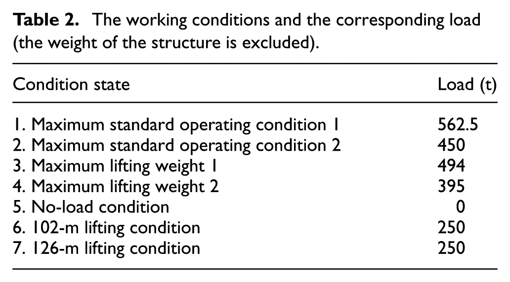
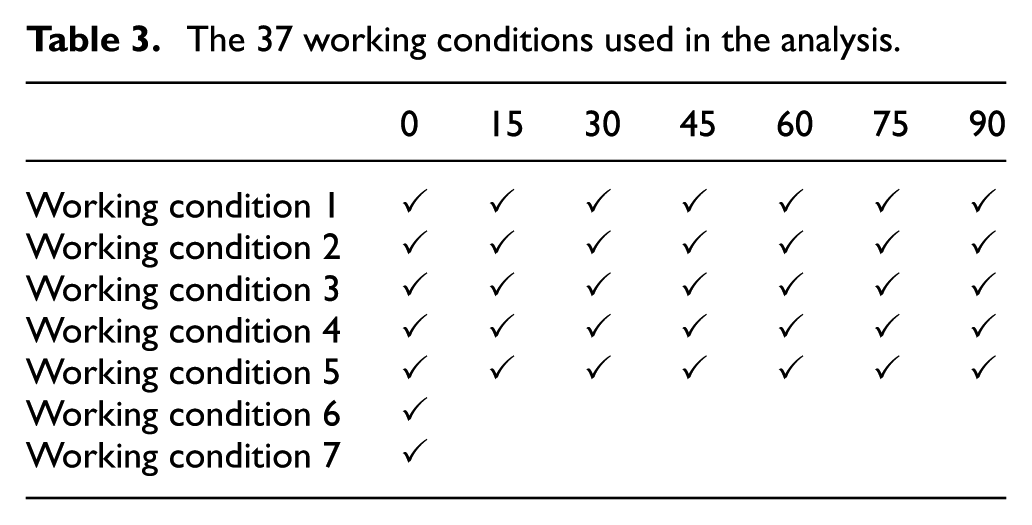
The frame is utilized to transfer the load generated from the rotary support to the chassis. The loads and constraints of the vehicle have great influence on the stress distribution of the frame, and hence, the full-model analysis should be executed at the primary stages of design. The process of defining working conditions is divided into three steps: (1) extracting the force and torque at the center of the upper surface of the rotary support, (2) transferring the results to the frame by REB2 elements, and (3) taking the rotary support shaft as the center of rotation and dividing the 90° angle into seven groups on average (as shown in Figure 4, the 0° angle has 7 working conditions which are listed in Table 2, each of other angle has 5 working conditions (conditions 1–5), a total of 37 working conditions in the design process). Table 2 lists the seven working conditions which are the guideline to the load application. Table 3 displays the specific working conditions used in the analysis of frame (working conditions 1–7 in Table 3 refer to condition states 1–7 in Table 2, respectively).
The working conditions and the corresponding load (the weight of the structure is excluded).
The 37 working conditions used in the analysis.
As shown in Figure 3, the frame is characterized by 268,134 hexahedral elements, and the crawlers include 461,864 elements, which cause a large burden to the computer due to the complicated structure and the huge number of units. Computation efficiency will be reduced, even cannot be solved. What is more, the crawler cannot be simplified into RBE2 structure because the direction and magnitude of the load of the domain connected to frame and crawler always vary with the change in working condition. In order to reduce the freedom of the FEM and improve the computational efficiency, parametric design strategy based on super-element (SE) technique is employed in the analysis.
Brief introduction to SE
The traditional method dealing with such an optimization problem is based on the full-model analysis. However, it will lead to calculation uneconomic due to the large amount of elements. In addition, simplifying the model structure by reducing the number of the elements will cause inaccurate results.
In order to address the two concerns of large computational load and low accuracy, a novel reduction technique for complex structure is employed in this article, namely, SE-GMP. By the method of SE-GMP, the complex models of nonlinear components can be simplified, while the important nonlinear effects will be taken into account. Simultaneously, the components processed by the approach can easily combine with other components in a multibody model. 19
Many academic studies can be identified which attempt to solve the computational efficiency of the large model. Ambrosio and Verissimo 20 proposed a method which permits capturing the global nonlinear behavior of bushing-type elements in an efficient mode. This approach is evolved from sub-system global modal parameterization (GMP) method which can be treated as a generalization of the SE method. 21 Brüls et al. 22 first put forward the idea of GMP method which is used to describe the rigid motion of the system and reduce the amount of degrees of freedom (DOFs).
Basic theoretical equations of SE
The purpose of the SE analysis approach is to replace the internal DOFs of the submodels with the boundary DOFs. Then combine these structures which without internal DOFs to the original model (master model) using the FE method and perform the analysis. For the corresponding mathematical formula, refer to Zuo et al., 23 which simulated the flexibility of joint using SE based on Guyan reduction method. The approach and result can be utilized as guidelines for the design of crane frame to simplify the model.
Figure 5 shows the modeling process of SE model which consists of several main steps: (1) specifying design domain and nondesign domain, (2) defining the boundary DOFs of the SEs, (3) deleting the component which will be retained in the subsequent optimization, (4) defining a parameter to write out the reduced matrices to an external file and then run the analysis, (5) re-retrieve the crane model and deleting the SEs, and (6) performing the topology optimization with SEs.

Schematic diagram of the super-element structure.
The most critical step in the process of modeling SE is to extract the components that need to be calculated from complex structures, and this involves the boundary simulation of the component. This problem can be achieved by direct matrix input grid (DMIG) method. Using DMIG approach, the external information of the component can be input into the Nastran calculation document in the form of equivalent matrix. Thus, the component can obtain the same boundary conditions as it in the overall FEM. The related mathematical formula can refer to Guyan reduction method. 23 Figure 6 indicates the flowchart of the parameterized software development program of crawler crane.

The flowchart of the parameterized software development program of crawler crane.
The results of working condition analysis
As discussed in section “Working condition analysis of the original model,” a total of seven working conditions are considered in the mechanics analysis (namely that when the angle of the rotary support is 0°). In working condition 1 (namely, the overweight lifting condition of the crane), the rotary support is prone to move forward and which leads to the case that the connection part to the frame and the front area of the rotary support is subjected to large load. The maximum von Mises stress under working condition 1 is 495 MPa. The computational accuracy needs to be further improved because the stress around the shaft which is connected with the frame and crawler is generally great, and such situation is considered inaccurate according to the engineering experience. Hence, in order to clearly express the stress distribution of the frame, the upper bound of the stress is set to 330 MPa as shown in Figure 7; thus, only the domain where the stress is greater than allowable stress is displayed. It can be seen from this figure that the stress distribution of the frame is quite irregular. Hence, topology optimization is employed to redesign the frame structure.

The stress distribution of the frame under seven working conditions.
From working conditions 2–7, it can be obviously found that the maximum stress is lower than that of working condition 1, and simultaneously, the high-stress area is also smaller. By comparing the stress distribution of frame under seven working conditions, it can be found that the overall stress level of the frame is prone to concentrate on both extremes. Namely that the stress is very high in high-stress area, and in the contrary, the stress is very low in the low stress domain. In this article, due to the unreasonable stress distribution, many important design requirements should be concerned when the lightweight design of the frame is carried out, such as the compliance, stiffness, and durability. Typically, stiffness is the most important boundary condition among the targets mentioned above. Hence, the stiffness is chosen as the design objective for the following topology optimization, while leaving other performance parameters as the design constraint.
Table 4 lists the FEA results of the frame. It can be noted that the performances meet most of the design requirements. Hence, the results can be set as the constraints in the topology optimization. For this analysis, a total of 50 iterations are required until convergence with the central processing unit (CPU) time of 15.4 h on the personal computer (PC) platform (WINDOWS Opteron Processor, 16 cores, 128-gigabyte memory), which has a 70% reduction in total computation time.
The FEA results of the frame under seven working conditions.

Topology optimization theory
Structural topology optimization is a simple and effective design tool for obtaining lighter structures. Various interpolation functions and penalization techniques for density-based method have been proposed such as the SIMP method,24,25 the ESO method,26,27 and the rational approximation of material properties (RAMP) method. 28 Due to the maturation of these classical topology optimization techniques, they have been widely used for the lightweight design of structure. For example, Zuo and Saitou 29 present an ordered multi-material SIMP to solve multi-material topology optimization problems.
In order to obtain clear images of optimized structures, the intermediate values of density design variables must be removed during the process of topology optimization. For this purpose, the method of SIMP is employed in this article. In this method, the design domain is discretized, and the special physical density ρi is chosen to represent distribution of material

where E and ρi denote Young’s modulus and the relative density of the ith element in the design domain, respectively; E0 represents the real physical quantity of the base material; and p is the penalty factor, which is used to make the intermediate densities unfavorable in the optimized solution.
For the SIMP method, the constraint conditions and objective function can be converted to each other, namely that the compliance, mass, volume, and stress can be set as the constraint conditions or the objective function.
In order to describe the process of optimization better, the design procedure is divided into two steps: topology optimization and thickness optimization. The concerned performances during the two optimization steps are different. In topology optimization, a new layout of crane frame is obtained with the maximize stiffness and the minimize stress. The most distinctive feature of utilizing topology optimization is that a new design completely different from the existing structural can be obtained. This is because topology optimization starts from a simplified initial model instead of modifying the existing models and then searches for the best structure among all possible solutions within the design domain model. In the thickness optimization step, the layout of the model remains unchanged, while the thickness of each plate is adjusted. Finally, an optimal design of the frame can be obtained.
Topology optimization of the frame
Topology optimization of the original model
From the analysis of the frame, it can be found that working condition 1 is most crucial. Its maximum stress is greater than that of all the other cases, and simultaneously, the corresponding high-stress region contains all the other high-stress areas. Therefore, working condition 1 will be seriously concerned during topology optimization.
As shown in Figure 8, the full model of the crane frame is divided in two parts: a design domain and a nondesign domain. The dark areas, namely, the design domain, are utilized for the topology optimization. It can be seen that the design domain is large enough, and the original frame structure is completely embraced in it. A total of 664,219 hexahedral solid elements are employed in the design domain. The bright areas are excluded from the topology optimization, namely, the nondesign domain and which will keep the structure unchanged during the optimization. The parts in the nondesign domain are utilized for fixing and installing of other components of the crane. The loading conditions and parameters used for the topology optimization are the same as the FE model in section “FEA of the original frame.”
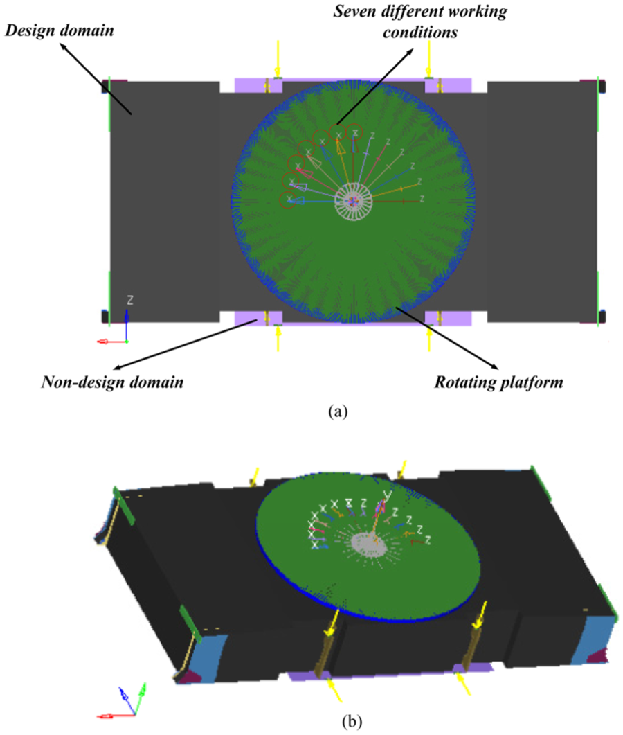
Design domain of the crane frame: (a) top view and (b) isotropic view.
The topology optimization of the crane frame is solved using professional software OptiStruct, which is a powerful solver, and it can perfectly interface the software Altair Hypermesh. The advantage of using OptiStruct is the constraint screening technique which can greatly improve the efficiency of calculation. Stress screening is one of the functions of constraint screening and which is active by default in OptiStruct. The main design features of OptiStruct include topology optimization, shape optimization, and size optimization.
In this work, the topology optimization design of the crane frame is carried out utilizing SIMP method. The purpose is to minimize the mass of the structure. With this aim, important constraint conditions that must be considered through the whole design process are the compliance, maximum stress, and displacements of load-bearing surfaces. The optimization problem for the crane frame can be mathematically stated as


where M is the mass fraction; M and M0 are the volume after and before optimization, respectively; N denotes the total number of elements; νi represents the volume of the ith element; ρi is the corresponding density of the ith element; ki and k0 are the current stiffness and initial stiffness of the material for the ith element, respectively; p is the penalty factor, and it was set to 3 in this work; c denotes the compliance; U is the vectors of nodal displacement; F represents the force; K denotes the global stiffness matrix; C is the upper bound of compliance;
Result of the topology optimization
Figure 9 indicates the schematic diagram of optimized topology. For the optimization of the frame, the density threshold is set to 0.3, namely that the elements whose density values are <0.3 are not illustrated. Three design concerns are revealed from the result of topology optimization: (1) ribbed slab structure, (2) hollow inside part, and (3) arc-shaped plate. Ribbed slab structure is generated due to the transmission path of the load, namely that the domain around the ribbed slab structure is subjected to more load. Hollow inside part indicates that the elements in the region are completely removed because their density values are smaller than 0.3. However, such structure is prone to buckling phenomenon. Arc-shaped plate belongs to thin plate structure which has benefits on load bearing, but it will cause problem such as manufacturing difficulty.

Geometry extraction from the result of topology optimization.
In order to address all these concerns, a post-processing model is proposed, as shown in Figure 10. A total of eight obvious changes are displayed compared to the original model. In this figure, the character “S” denotes the shape of design variables. As the problems mentioned above, the ribbed slab structure is replaced by two bending plates, namely, S1 and S7. The distribution of stress and layout of the pipeline are of two significant concerns for the design. The purpose of S2 and S5 is to enhance the plane stiffness of the circle plate and avoid the occurrence of buckling. The rib installed on the connection part to the circle plate and bending plate (shown as S3 and S6) can decrease the local stress and eliminate the stress concentration phenomenon. The circle structure, due to its simple manufacturing process, is utilized to replace the original semicircular structure. The appearance of the bottom plate of the frame varies from quadrilateral to oval shape. The advantage of the new structure is that it can reduce the stress concentration. The optimization history of the compliance and stress is shown in Figure 11.

Detailed design of the frame which will be used as the thickness design variables.
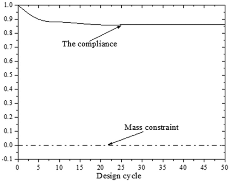
The optimization history of the compliance with the mass constraint.
The von Mises stress of the cover plate should be considered separately due to different materials and load modes. Figure 12 shows the stress distribution of different materials of the frame under seven working conditions. It can be noted that high-stress areas are within the scope of a single element, and hence, their values cannot be considered in the analysis.
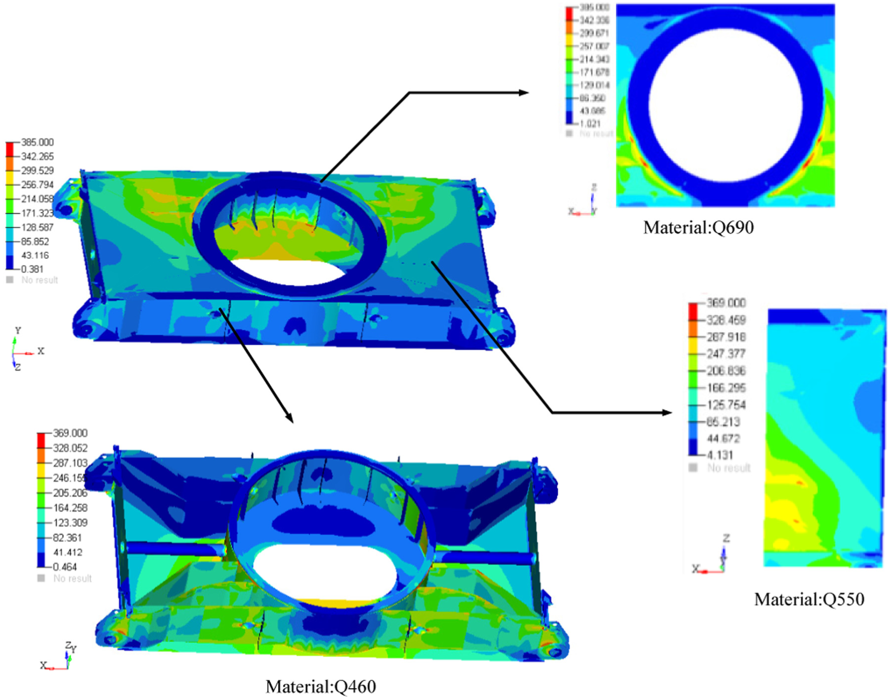
The stress distribution of the frame after topology optimization.
Considering that different materials have different fatigue strength, Table 5 lists the performances of the post-processed frame. Compared to the original model, the compliance decreases to 12.142%, and the von Mises stress of the structure also declines to an allowable value.
The comparison of the performance of different materials for the original model and post-processed model.

Thickness optimization
The performances of the optimized structure have improved compared to the original model. However, as the post-processed model is based purely on the engineering experience of the designer, it can be further designed using thickness optimization. At present, topology optimization is usually used as the conceptual design, and shape and size optimization is used in the detailed design stage to further minimize the mass. 30
The design variables for thickness optimization are shown in Figure 10. The post-processed frame structure consists of 8 plate members (in fact, a total of 28 plates are divided into 8 groups due to the symmetric structure of the frame), each of which has its corresponding design variables for thickness optimization.
The formulation for the proposed thickness optimization can be defined as


where Ai denotes the area of ith plate of the frame and ti represents the thickness, the design variable for the optimization. Hence, the objective of function Gs(t) is to minimize the total mass of the frame. In equations (5) and (6), the characters C0 and σ0 refer to the compliance and stress of the frame in Figure 10, respectively. So, equation (5) constrains the stiffness of the frame to be at least equal to that of the post-processed frame-based topology optimization in the thickness optimization process, and simultaneously, the stress of the structure is subjected to the same constraint by equation (6). Thus, the target of the lightweight design is to reduce the mass of the frame as much as possible while maintaining the performances of the topology optimization result.
In order to save manufacturing cost, the values of the plate thickness after optimization are chosen from the samples which can be mass-produced. The optimized thicknesses are listed in Table 6, and the corresponding optimization history is shown in Figure 13. The performances of the frame after thickness optimization are listed in Table 7. It can be noted that the mass decreases to 15.12% compared to the original frame structure, while the performances of the frame improved.
The optimized thickness of variables of the frame (

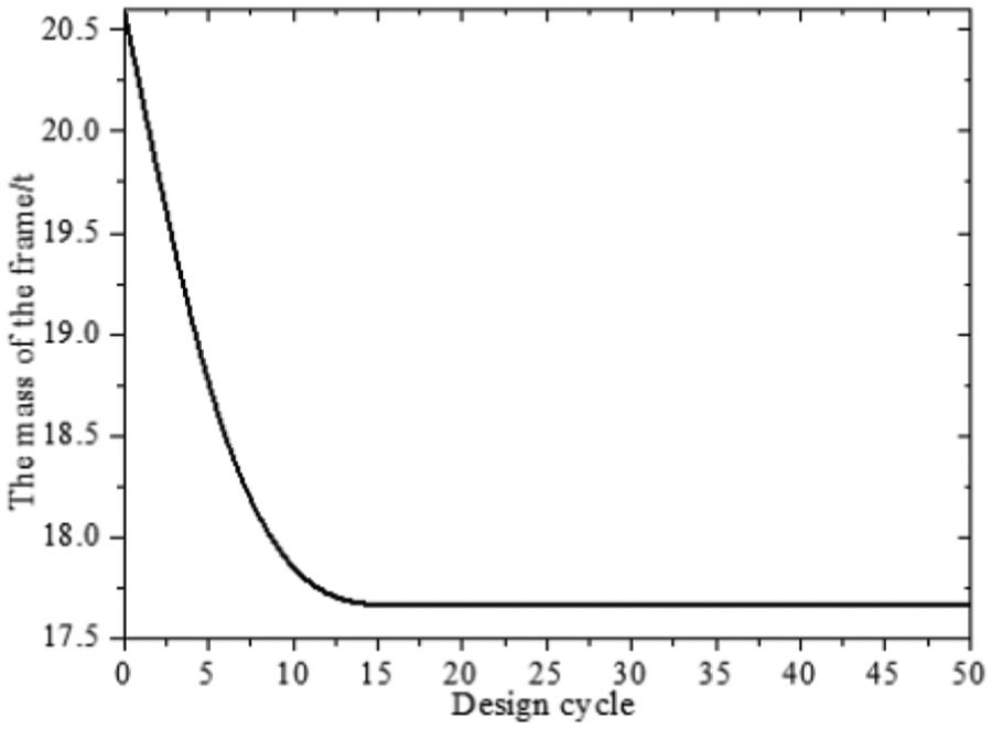
The mass iteration curve of the frame.
The comparison of the performance of different materials for the original model and thickness-optimized model.

Validation of the optimization design
In order to ensure the validity of the optimized structure, two verification means are performed: (1) the FEA of the model is carried out under 37 working conditions and (2) durability tests are performed based on the different working conditions.
Figure 14 shows the final FEA results of the frame. As discussed in section “Working condition analysis of the original model,” a total of 37 working conditions are considered in the analysis. Three different materials Q690, Q550, and Q460 are used in the model, and obviously, their performances satisfy all the design requirements.
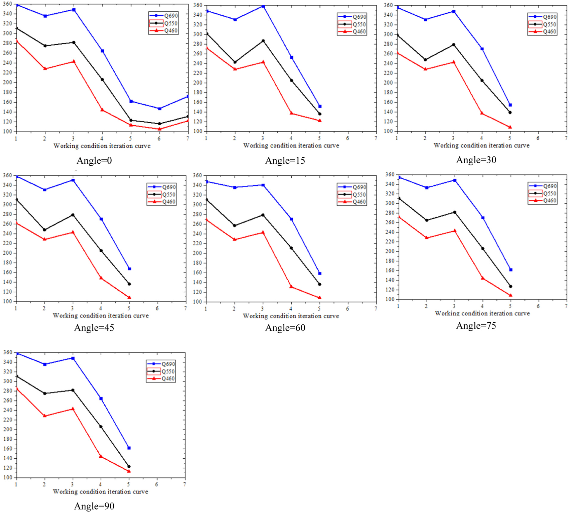
The final FEA results of the frame under 37 working conditions (the numbers from 1 to 7 represent the seven working conditions which are listed in Table 2).
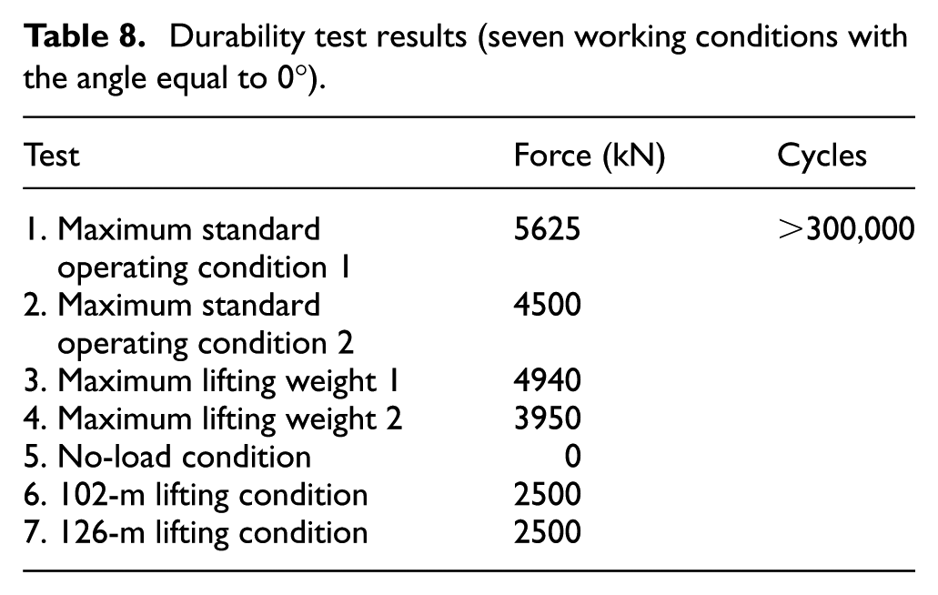
The product integrity should be ensured during the lifetime, and therefore, durability is also an important index. Durability tests are performed by applying the loads (Table 2) on the optimized structure, and the corresponding results are listed in Table 8. The performance requirement for durability is >300,000 cycles. Obviously, the product satisfies the durability requirement.
Durability test results (seven working conditions with the angle equal to 0°).
Conclusion
This article proposes an effective design strategy for the lightweight design of crawler crane frame, including two major design steps: conceptual design (topology optimization) and detailed design (thickness optimization). In this work, topology optimization which is based on SIMP method is employed for conceptual design, and SE-GMP algorithm is used to reduce the complex model. Based on the result of topology optimization, thickness optimization is introduced to further minimize the weight of the structure. In order to validate the validity of the FEA, a full-condition simulation and anti-fatigue test are carried out. Finally, the crane frame has a 15.12% decline in the weight compared to the original model, which is more than the required 14%.
According to the whole analysis and optimization process, several important conclusions can be drawn:
SE technique is a novel and efficient method to deal with the complex structure. Using SE technique, the complicated multibody structure can be divided into several reduced models of components. Moreover, these simplified models can be efficiently coupled with the original models. The most attractive feature of SE technique is that it can improve the computational efficiency without destroying design accuracy.
The thickness design is used to further optimize the frame, which is more accurate than only using topology optimization. This is because post-processed model from topology optimization is based purely on the engineering experience of the designer.
Through topology optimization, a novel frame structure can be obtained which is different from the existing one. This is because topology optimization begins from a simplified design domain instead of modifying the original model. Finally, a best layout among all possible solutions is obtained which achieves the purpose of lightweight without losing the frame performance.
The full-condition simulation and anti-fatigue test are carried out to validate the validity of the whole design.
Footnotes
Academic Editor: Byung Sun Kim
Declaration of conflicting interests
The author(s) declared no potential conflicts of interest with respect to the research, authorship, and/or publication of this article.
Funding
The author(s) received no financial support for the research, authorship, and/or publication of this article.