
Abstract
This study investigates the characteristics of helical abrasive brush filaments and aims at developing a mobile robot system to perform rust removal and polishing tasks. A finite element model that can analyze the filament deformation and force characteristics is presented. From the model, the relationships between the brushing force and other operating parameters can be predicted, which are essential for developing an autonomous brushing control system. The modeled results are compared with experimental results carried out on a specifically designed test rig, leading to considerably well converged comparisons. Many later studies can be carried out to develop optimal brush control strategies for autonomous rust removal or polishing tasks.
Introduction
Metal abrasive brushes are widely used in industries for deburring, finishing, polishing, and rust removal processes.1–6 Automatic finishing or polishing machines are often large workstations that require operators to handle materials at specific locations. For many remote applications such as bridge and vehicle shell refurbishment, handhold tools such as angle grinders are often equipped with abrasive brushes for labor works, as shown in Figure 1(a). These are not only time-consuming but also labor intensive. It will be a significant enhancement to develop a mobile robot system using a compact robot arm and abrasive end effectors to accomplish these tasks. Similar equipments are still rare in the market7,8 due to difficulties of controlling the end effectors; thus, it is necessary to investigate the characteristics and effectiveness of the brush tools.

Cup type abrasive steel brush and its application: (a) rust removal with an angle grinder and (b) structure of cup type abrasive brush.
There are several variations of the abrasive brush tool structures such as circular type, roller type, and cup type. This study is focused on the cup type brush as shown in Figure 1(b) that is currently widely used on handhold grinders. The brush filaments are often helical steel or copper wires instead of straight wires. Studies on brush tools have been limited to a few areas such as nylon tooth brushes or industrial brushes on road sweepers or polishing stations. In the former cases, many investigations have been carried out by testing and clinical statistics rather than engineering analysis. 9 In the latter cases, some earlier studies have been focused on modeling brush filament deformation and force analysis,10–15 and more recently, studies have been shifted toward magnetic assisted grinding effects that can only be applied to large polishing workstations.16–18
This study is more interested in brush force characteristics similar to those for metal brushes on road sweepers.10–15 Studies on the sweeping brush aspect have been mainly based on finite element (FE) modeling brush deformation, dynamic modeling brush vibrations, and statistically investigating brush characteristics from FE modeling results. These studies involve analyzing the deformation of straight rectangular brush tins using FE beam elements under complex loading conditions. By changing brush tine geometric parameters and loading conditions in the model, such as length, thickness, aspect ratio, rotational speed, compression displacement, different results have been obtained and the regularities have been presented. 15 These contribute a good basis of methodology for the current study, although a major difference is that the abrasive brush filaments are helical in this study; thus, a different modeling approach has to be adopted.
Theoretical analysis
The helical brush filaments are often steel with typical diameter of 0.2–0.3 mm and length between 20 and 30 mm, as shown in Figure 2(a). The steel brush is quite strong and stiff for its short filament length and suitable for rust removal or deburring. In some other cases, copper brushes with smaller diameters are used for refined surface treatment.

A helical steel filament and its idealized model: (a) a helical steel filament and (b) a helical spring model.
Omitting the geometrical irregularities, an idealized model of a helical filament can be a spring, as shown in Figure 2(b), with one end fixed and another end mainly subjects to contact force from the target surface. The vertical contact force Fv can be resolved into a lateral force Ft and an axle force Fx, and the former causes a bending moment similar to the effect on a helical cantilever beam. Assume such a helical cantilever beam is compressed onto a target surface, and the distance from the brush to the target surface remains constant, then the vertical contact force Fv is constant. In such an equilibrium state, the deformation caused by Ft can be expressed as

where φ is the angular rotation of the two ends of the spring, M is the bending moment due to Ft, x is the length per circle, G is the shear modulus, and Ip is polar moment of inertia. When a spring is straight, the deformation caused by the axel force Fx can be written as

where λ is the axle displacement; D, d, and n are the spring diameter, wire diameter, and number of circles, respectively; and the division term can be represented by the well-known spring stiffness k. This applies to the helical filament when the deflection due to tip contact is not significant. When the deflection is large, however, the force Fx is not along the spring axle, which makes it difficult to carry out conversional mathematical analysis.
In an actual brushing process, there are many other factors involved, such as friction at the tip, centrifugal force due to large rotational speed, and large deflection due to complex loads, which are difficult to investigate using mathematical methods. Therefore, a FE model has been developed to analyze the situation.
Finite element modeling
It was assumed that the brush filaments are equal in geometry and can be investigated using one example, although this limit may be overcome in further studies. Mathematically, a helical line can be described by the following equation

where r is the coil radius, θ is an angular parameter, and h is the distance between neighboring two circles. The above was used in FE software ANSYS to produce a series of key points to represent a helical line. In order to produce an actual helical line, these key points cannot be linked directly with L commend since this leaves sharp corners at each key point. Instead, SPLINE command was used to fit every six neighboring key points, and then a LGLUE command was used to merge all the segments into one helical line and then meshed by three-dimensional elements BEAM189. Some examples of mashed helical line models with varying radii and coil distances are shown in Figure 3.

Meshed helical line models: (a) three circles, r = 1 mm; (b) five circles, r = 1 mm; and (c) three circles, r = 2 mm.
The loading conditions applied to a helical filament include position constraints at the top, support force Fv from the target surface, frictional force f on the tip, and centrifugal force Fc on the filament body, as shown in Figure 4. Since large deformation occurs on the filament, the location of a specific point on the filament body will not be the same as that before deformation, which may affect the directions and parameters of the centrifugal force and the frictional force. This means conventional loading and solving approaches will not be suitable.

Loading conditions on a helical filament when the brush is compressed and rotating.
To deal with the above issue, a ramped loading approach has been used to solve the deformation equilibrium in multiple steps. The calculation starts from nonrotating state above the target surface. Then, rotational speed is increased and the brush is pushed down to make contact with the target surface. This procedure is implemented in multiple steps, and in each step, the geometry results from the last step are retrieved using *GET command in order to calculate force direction and parameters for the next step. The centrifugal force on a specific node in the ith step in the ANSYS global coordinate system as shown in Figure 4 can be written as

where m represents the mass of an element containing this node; ω is the brush rotational speed;

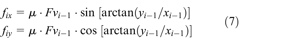
The frictional force on the target surface is complex and it is the major contributor to the brush abrasive effects. In this study, it is assumed that the friction can be described by a coefficient u while more complex abrasive effects should be investigated in the future. The frictional force on the filament tip in the ith step can be given by

where
Following the above methods, the helical filament is loaded and solved in multiple steps until the final deformation results are produced.
Modeling results
Using the above modeling and loading approach, many results can be obtained from ANSYS. This study investigates a typical helical steel filament with parameters, as shown in Table 1, and discusses the results afterward.
Parameters of an example helical steel filament.

The deformation results can be obtained and viewed in ANSYS, and the stress distribution due to complex loads can be viewed to help identify the mechanism of brushing. Figure 5 respectively shows the tensile stress along filament central axis SX, the shear stress in filament cross-section in two directions SXY and SXZ. Comparing with straight filament in which the stresses are concentrated at the clamped top end, the stresses in helical filament distribute separately at different circles and locations where the curvatures are large. This suggests that in helical filament, the loads are better distributed than straight filament.
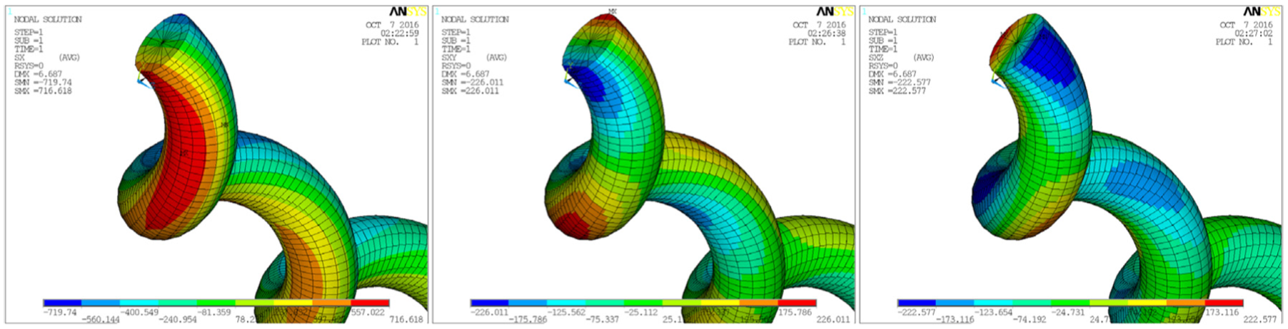
Deformation and stress distribution results.
The study is more interested in the force results obtained on the filament tip since this reveals the load applied to the target surface and is associated with the abrasive effects. The vertical contact force against increasing vertical displacement is shown in Figure 6, subjected to varying conditions of other factors. From Figure 6(a), it can be seen that large rotational speed reduces the force, since the centrifugal force pre-deflects filaments in a radial direction. However, the filament stiffness has not been much affected since the curves are nearly parallel. Small rotational speed does not affect brush force and geometry very much due to short length and small weight of the filaments. The contact mechanism between filament tips and metal surface is complex and beyond the scope of this article. A coefficient of friction is used in this study to describe the relationship between the contact force and the friction. Later investigations will be focused on the contact and abrasive effects.

Effects of rotational speed and friction on the filament force and displacement relationships: (a) effects of varying rotational speeds and (b) effects of different frictional coefficients.
However, the frictional coefficient does affect the geometry of a deformed brush since the frictional force drags filament in a tangential direction, which can be described by a friction angle ψ in Figure 4. The variation of friction angle due to different frictional coefficients is shown in Figure 7.
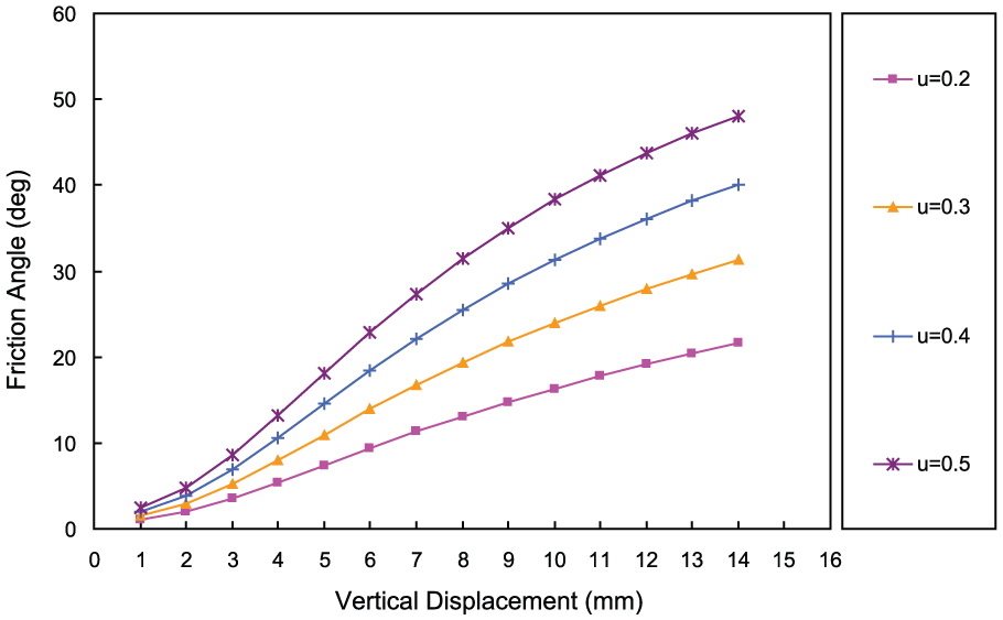
Variation of friction angle due to different coefficients of friction.
In the case of different filament geometries, such as different numbers of circles and different coil radii, the relationships between the vertical contact force and displacement are shown in Figure 8. It can be seen that increasing number of coils reduces the vertical contact force, and larger radius of the coils also reduces the force.

Effects of helical geometry on the filament force and displacement relationships.
The FE modeling approach can give many useful results, however currently it still can not reflect all the complex effects during brushing, such as the interactions between neighbouring filaments. These should be included in later studies. Nerveless, there are still several imperfections in the FE model, for example, the neighboring helical filaments may be locked together to form a nested effect, which should be investigated more thoroughly in the future.
Experiments
A test rig as shown in Figure 9 has been constructed in the lab to verify the FE modeling results. The test rig consists of a base plate, a top plate, four guiding rails, a sliding mechanism that can move up and down along the guiding rails, a lead screw to push and drag the sliding mechanism, and a direct current (DC) motor mounted on the sliding mechanism to provide brush rotation. The lead screw accurately provides 5 mm displacement when it is rotated 360°, and a turning wheel is mounted on the top of the lead screw to control degrees of rotation and thus the displacement in the vertical direction.
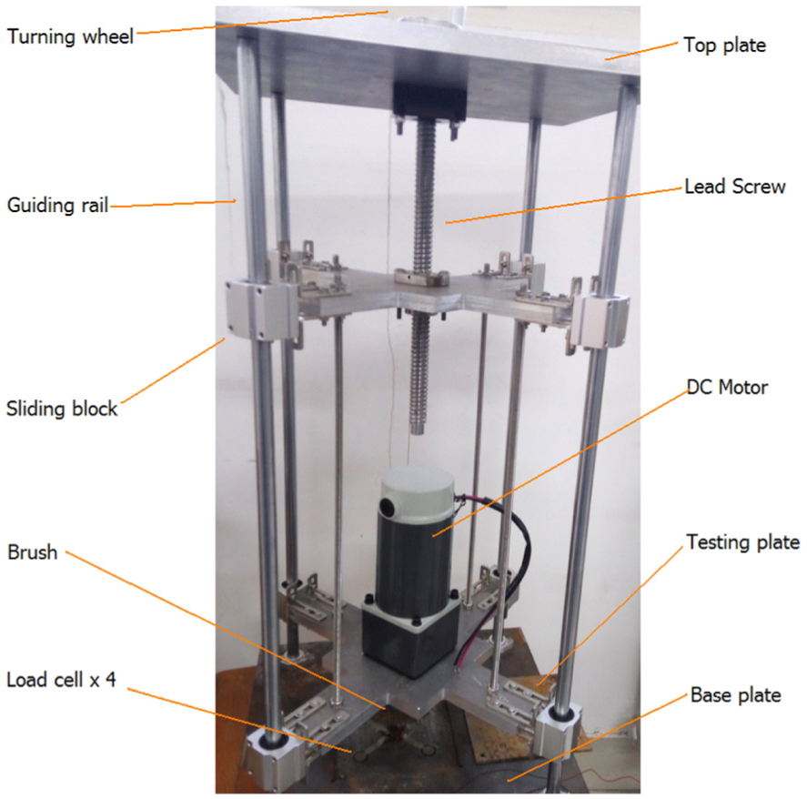
A test rig for testing abrasive brush load on metal plate.
A square groove is left in the bottom base plate in order to hold replaceable testing plates for experiments. Four identical film type load cells are attached on the groove surface, beneath the testing plate, which can measure the average load that the testing plate has experienced during brushing tests. The status of a brushing test and the surface state of the testing plate after a number of heavy load tests are shown in Figure 10. The test plate has undergone many experiments for force measurement. Long duration and large force has left scratches on the testing plate which is not successful in terms of rust removal purpose. This from another side indicates that a proper contact force and duration should be maintained in brushing. The optimal control strategies will be investigated in later studies.

Brush testing status and the effects on testing plate after the experiments.
The brush forces measured with 200 r/min rotational speed and varying penetration displacement are compared with the FE modeled results in Figure 11. The FE model assumes that the total brush force is simply a sum of all the forces over totally 1400 filaments, which likely cannot fully represent the actual situation. In reality, the filaments are not completely installed in the same manner, and helical wires may be locked onto neighboring wires and form a nested lattice. The difference projected onto the 200 r/min results is more obvious. When the vertical displacement is small, the actual measured force is lower than the FE modeled force, probably because the filaments are not identical in length and some are not in contact with the target. When the vertical displacement is large, the actual force appears to be higher than the FE modeled force, likely due to the nested effects. Therefore, when use the current FE model to predict force, a correction factor should be used to adjust the differences.

Comparison between modeled and measured brush forces at 200 r/min.
In order to measure brushing force with high rotational speed, a 1 kW DC motor has been installed which can maintain 4000 r/min rotational speed and 2.4 N m torque, or up to 10 N m torque when a gear box is added. Typical handhold grinder uses constant high speed motor up to 10,000 r/min to drive the abrasive brush, which limited by the rated power can not withstand large torque. This study intends to investigate the effects of rotational speed and torque in order to find the optimal operating method, therefore a DC motor with adjustable speed was used. From Figure 12, it can be seen that at 4000 r/min, the brush force correlates better with the FE modeled results, likely because the centrifugal force pre-deflects the filaments in a more symmetric manner, thus reduces the odds as shown in Figure 11.

Comparison between modeled and measured brush forces at 4000 r/min.
At present, the test rig is only employed to verify the brush characteristics simulated in the FE model. In further studies, many investigations can be carried out to fully understand the abrasive brush operating principles and ideally produce optimal control strategies for different tasks.
Conclusion
This study investigates the characteristics of helical abrasive brush filaments for developing a mobile rust removal and polishing robot system. A FE model has been developed to investigate the deformation and force characteristics of the filaments. The model first produces variable-controlled helical wire model in ANSYS and then applies multiple constraints and loads on the model to obtain deformation and force results. From the results, the relationships between brushing force and other operating parameters can be predicted, giving the following conclusions:
The rotational speed adds centrifugal effects to the filaments and lowers the contact force when the brush position remains unchanged. However, the centrifugal effect is not obvious when the rotational speed is below 2000 r/min.
The filament stiffness is not significantly affected by the frictional coefficient, as indicated in Figure 6(b). This means the applied brushing force may remain the same in different operating scenarios, however the lateral frictional force on the target surface may present different effects.
The helical geometry has large effects, for example, more circles in the wire lead to lower force, and large radius of the coil leads to lower force.
The comparison between modeled and experimental results suggested that there are odds at low rotational speed, likely due to unsymmetrical brush geometry and nested effects, while the results with high rotational speed are better converged.
In the future, many investigations can be carried out, such as the abrasive effects on different target surfaces, theoretical and experimental studies on surface treatment mechanisms, effects of filaments interactions and optimal brush design, optimal brush control strategies for different tasks. These outcomes can assist the development of an advanced mobile robot polishing system.
Footnotes
Academic Editor: Filippo Berto
Declaration of conflicting interests
The author(s) declared no potential conflicts of interest with respect to the research, authorship, and/or publication of this article.
Funding
The author(s) disclosed receipt of the following financial support for the research, authorship, and/or publication of this article: This study is supported by the Scientific Research Fund of Liaocheng University, China (grant no. 3180500/318011519), Shandong Higher Education Institutions Science and Technology Program (grant no. J17KA028), Collaborative Innovation Center for Shangdong's Main Group Production Equipment and Mechanization, and Shandong Province Natural Science Foundation (grant no. ZR2016FL13).