
Abstract
Recently, cable-driven parallel robots have been used in many industrial fields. Especially, cable-driven parallel robots have been used in specialized industrial fields where dynamical features such as high accuracy in systems requiring quick transitions. In this article, Dahl friction model was proposed to predict the tension during quick transitions in cable-driven parallel robots. And the Dahl friction equation for a combination of pulleys connected in series was derived. From their relationships, a modified kinematic equation was developed for redundant actuation cable-driven parallel robot systems. Because Dahl friction has non-linear characteristics, the actual tension set problem was solved using the Newton–Raphson method combined with the constrained non-linear multivariable optimal method. Finally, the tension profiles were simulated using both Dahl and Coulomb friction models with fast and slow velocities. In conclusion, according to simulation, Dahl friction model expressed dynamic characteristics such as pre-sliding in the transition range. Thus, it was in better agreement with the experiments than the Coulomb friction model. In particular, Dahl friction model was more accurate in the case of slow motion in the pre-sliding range.
Introduction
Cable-driven parallel robots (CDPRs) have been used in many industrial fields such as disaster rescue, test rigs, construction, and broadcasting.1–4 Because of high sensitivity, low inertia, and large workspace,5,6 they have been even used in specialized industrial fields where dynamical features such as high speed and accuracy are required, 6 as well as in systems requiring quick transitions between moving states and high positional accuracy, for example, surgical robots and pick-and-place robots.7,8
General CDPRs include an end-effector, cables connected to a winch, and pulleys.5,9 However, the end-effector is negatively affected by non-linear dynamics and uncertainty in the behaviors of some components, resulting in cable elongation, winch friction, and pulley bearing friction.10–13 That prevents high-accuracy control. CDPRs requiring high position accuracy have a number of pulleys guiding each cable; thus, pulley bearing friction from cable tension introduces significant error, reportedly 11% 14 and 10% 15 in some cases. As such, researchers have tried to measure and compensate for pulley bearing friction. Kraus et al. 14 measured the tension using a load cell in conjunction with a pulley and proved experimentally that friction is the predominant factor affecting tension; they then proposed an algorithm to compensate for the friction using the Dahl model. Miyasaka et al. 15 showed that Coulomb friction significantly affected the accuracy of the RAVEN-II surgical robot. Because the dynamic friction of pulleys affect dominantly the cable tension, these dynamic characteristics are essential for developing highly accurate models such as the control and determination of workspace.16,17 Although there have been some researches into the pulley bearing friction of CDPRs, there have not been any study to calculate the tension accurately using a dynamic friction model combined with kinematics. In our previous research, 18 we predicted the tension accurately using the relationship between tension and pulley bearing friction with a kinematic Coulomb model in a static equilibrium. However, the pulley bearing friction cannot be expressed simply in terms of Coulomb friction in dynamic status; in practical system, the quick transitions that occur during direction switching have non-linearity and affect the micro-displacement (i.e. pre-sliding) ranges of friction.19,20 And it significantly has a bad impact on the accuracy of CDPR system because errors caused by change of friction in pre-sliding range are continuously accumulated during the operation. Therefore, the kinematics with Coulomb friction model is not suitable enough for highly accurate control.21,22 The numerical friction model requires the appropriate dynamic representation that accounts for non-linear friction models, such as the Dahl23–25 and LuGre models.26,27
In this article, a Dahl friction model was proposed to predict the tension during quick transitions in CDPRs. Dahl friction equation for a combination of pulleys connected in series was derived. From their relationships, the modified kinematic equation was developed for redundant actuation CDPR systems. Because Dahl friction has non-linear characteristics, the actual tension set problem was solved using the Newton–Raphson method combined with the constrained non-linear multivariable optimal method. Finally, the tension profiles were simulated using both Dahl and Coulomb friction models. And for two cases of velocities of 0.26 and 0.026 m/s, the actual tension profiles were measured and compared with the calculated tension profiles of CDPRs moving along a pre-programmed route.
Model of redundant-actuated CDPR system
The CDPR system consisted of a frame (2 × 2 × 2 m3) and an end-effector (0.03 × 0.03 × 0.30 m3). The mass of the end-effector was 0.4 kg. For simplicity, the one condition is assumed that the geometrical center is identical to the mass center. Figure 1(a) shows the composition of the CDPR and the distribution of the cables and pulleys. The pose of end-effector is controlled by eight cables with diameter of 3 mm. Each cable was connected to five pulleys in series as Pulley1–5 (Figure 1(b)). Table 1 shows the position of first cable from end-effector. Each number of n means the pulley guiding each cable n. To avoid interference from each cable, the coordinates of Pulley1 are different upper and bottom sides. To reduce the moment of the end-effector, the upper side of the end-effector was connected to the bottom of the frame by a cable, and the bottom side was connected to the upper frame. 1 The wrapping angles from Pulley5 to Pulley2 are 90°, 90°, 14.50°, and 75.32° respectively. The wrapping angle of Pulley1 has a variable value to allow the end-effector to move along a specific trajectory. Using kinematical vector analysis, this system can be represented as follows
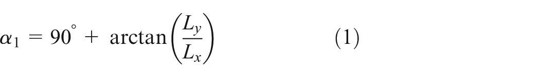
where α1 is the wrapping angle of Pulley1 and Lx and Ly are the x- and y-components of the cable length, respectively. The tension was measured using a force sensor (load cell, UMM-K200). The cable was made of Dyneema polyethylene, capable of withstanding 2000 N loads. 28

Model of a 6-degree-of-freedom (DOF) redundant actuation of cable-driven parallel robot (CDPR) system: (a) cable distribution and (b) pulley configuration connected in series. 16
Coordination of each pulley.

Kinematics and modification of the kinematics including the dynamic friction model
Kinematics of the 6-degree-of-freedom CDPR system
Because CDPRs consist of flexible cables, not rigid arms, it is important to predict the tension. Figure 2 shows the vector diagram used to derive the cable length; the derivation was based on inverse position kinematics (IPK).

Kinematic diagram of the CDPR system.
The general length vector equation describing the kinematic diagram in Figure 2 is given below
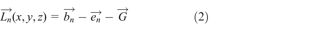
The vector from the bottom of the frame to the center of the end-effector is denoted as


where
where
Modeling the pulley bearing friction
As mentioned earlier, accurate predictions of tension require that pulley bearing friction be considered in the model. The normal force can be derived from the both of each tension applied to pulley and using the second law of cosines (Figure 3). The Coulomb friction in the static model can be described as follows 14


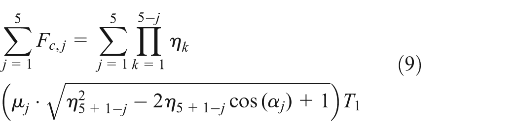
where the number of the pulleys connected in series is denoted by j,

where ηj is the loss factor of Pulley j . From equation (8), we see that the pulley bearing friction depends on the cable tension. Thus, the loss factor is introduced to decouple the cable tension and the friction factor as presented at our previous research. 18 Using equation (8), all of the five pulleys are described by
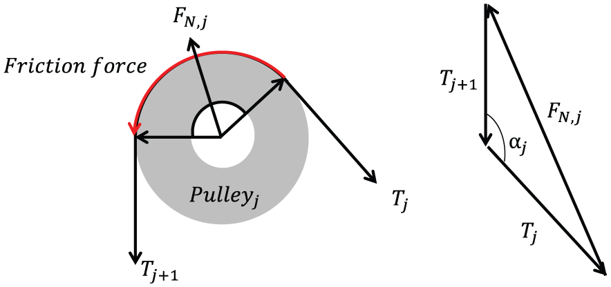
Free-body diagram of the pulley and the associated vector configuration.
Also, both Coulomb friction and viscous friction should be considered for higher precision. 29 However, because our CDPR system operates at a velocity below 10 m/s, the viscous effect is too small according to Miyasaka et al. 15 Thus, in this analysis, viscous friction is ignored. Additionally, we can take advantage of the simplicity of the Coulomb friction term to control the pose.29,30 However, Coulomb friction has limitations in that it does not take into account pre-sliding dynamics at low velocities.24,31 For this reason, Dahl friction is proposed. Using Dahl friction, we can model pre-sliding dynamics; these dynamics are non-linear when the velocity is close to zero. Dahl friction is presented as first-order non-linear ordinary differential equation. The general form of the Dahl friction model is given by the following 23

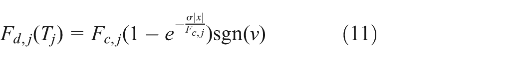
where

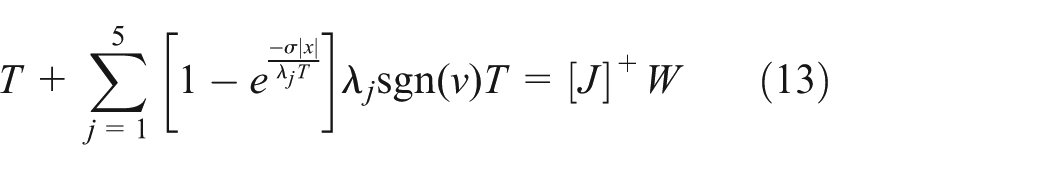
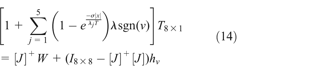

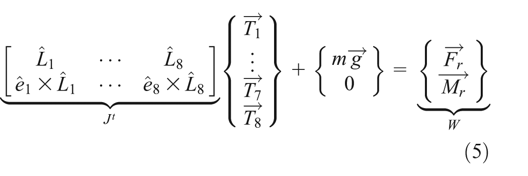
where [J]+ is the pseudo inverse matrix of J. By considering Dahl friction, equation (12) can be rearranged as equation (13) using the pseudo inverse matrix. To obtain the optimal value, the constrained non-linear multivariable optimal method
18
using equation (15) was applied as shown in equation (14). hv is an arbitrary vector (hv ∈
Analysis of cable tension including Dahl friction
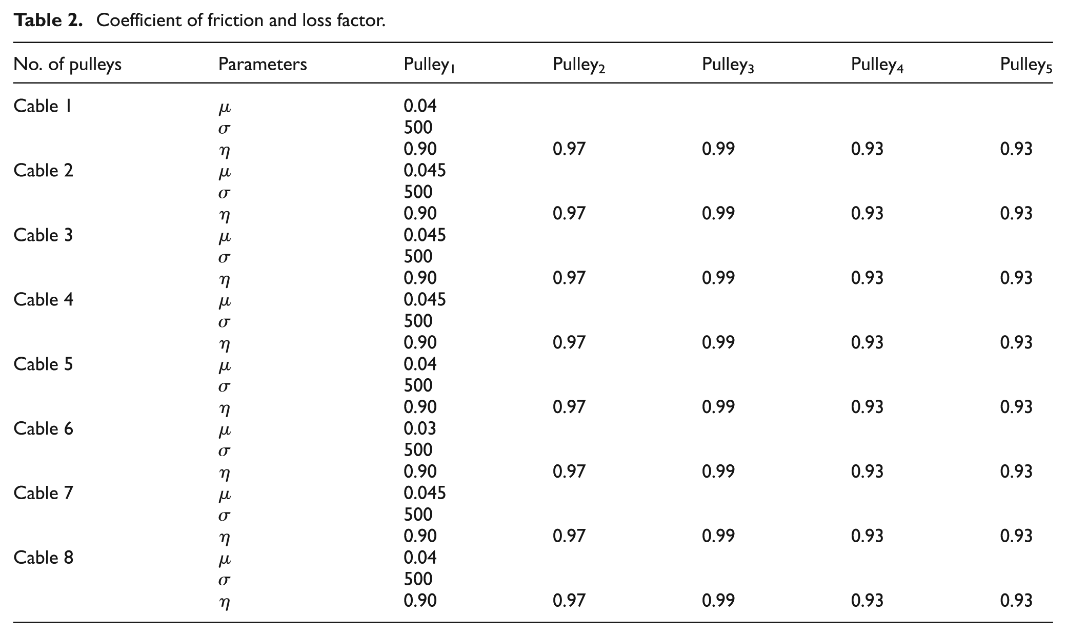
To assess our model, simulated results were compared to results measured while the end-effector moved along a pre-programmed route (see the lower part of Figure 4). In the experiment, the end-effector moved 0.2 m with velocities of 0.26 and 0.026 m/s in the x- and y-directions, respectively. The instantaneous acceleration of the end-effector is 10 m/s2. The friction parameters used in the simulation are summarized in Table 2. The details of the parameter choices are discussed in a previous study 18 and in many other publications.25,32 The friction parameters of the CDPR system may vary as the motion varies between slow and fast. In our simulation, for simplicity, the same parameters were used for both slow and fast motion. σ is the parameter that has the most significant effect on the pre-sliding range; it also reflects the dynamic friction characteristics. Therefore, we first varied σ to study the effects of changing the parameters. As σ is varied, so does the cable tension, including the dynamic friction. Figure 4 shows the variation of the tension profile with σ, and the red, green, and gray lines indicate the tension profiles for values of σ = 100, 400, and 700, respectively. At the transition range in the red circle in Figure 4, as σ increases, the gradient of tension increases. This is because the pre-sliding range decreases. As the pre-sliding range decreases, the Dahl friction arrives at a steady state more quickly. As σ increases, the tension profile considering Dahl friction meets tension profile including Coulomb friction. Based on these results, we selected σ to be 500 when tuning the experimental processes in this research.
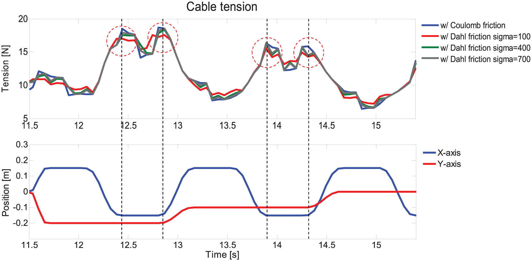
Effect of σ on the tension profile (velocity = 0.26 m/s).
Coefficient of friction and loss factor.
In the experiment, as the tension profiles were measured at Pulley4, the tension data were compensated. 14 Figure 5 shows the tension data obtained experimentally and by simulations in the case of fast motion.
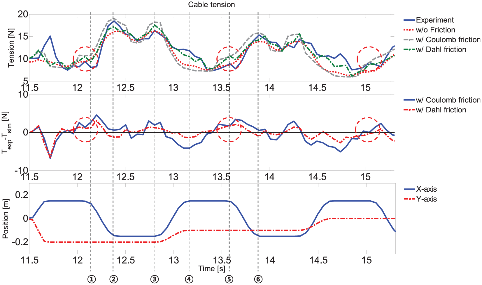
Tension profile and error for fast (velocity = 0.26 m/s) pre-programmed motion.
In the upper plot of Figure 5, the blue line indicates the measured tension profile; the red, gray, and green lines show the tension profiles when calculated with no friction, Coulomb friction, and Dahl friction, respectively. The tension profiles including Coulomb and Dahl friction are more accurate than the profile where friction is not considered, as shown in Figure 5. The middle graph of Figure 5 shows the differences between Coulomb and Dahl friction; the error over the entire range of movement decreased significantly with the Dahl friction model which was used as opposed to the Coulomb friction model. The total error over the entire range of movement was calculated; the mean and standard deviation of the error for the Coulomb and Dahl models were 1.89 ± 2.57 N and 1.23 ± 1.37 N, respectively. Moreover, the Coulomb friction profile showed a big difference in the transition section (points ①–⑥, Figure 5); Dahl friction model was in good agreement with the experimental data in this section. In the transition range, Coulomb friction is discontinuous where the velocity is nearly zero. In contrast, Dahl friction is continuous in the transition range as it can model the pre-sliding; Dahl friction is particularly susceptible to motion transitions like red circles in Figure 5. Besides, the pre-sliding part of the transition is dominant at the relative velocity between each surface. Table 3 shows the errors at points ①–⑥ for the Coulomb and Dahl cases; the mean error in the case of Dahl friction was 35% smaller than that of Coulomb friction during transition and the standard deviation also decreased 47% at the case of Dahl friction.
Errors at each transition point and total error (fast motion = 0.26 m/s).

Figure 6 shows the tension profiles for slow motion. The velocity is 0.026 m/s and the motion is similar to the fast motion. As shown middle plot, the case of Coulomb friction is less accurate than it was when modeling the fast motion case. The total error in the case of Coulomb friction is 2.06 ± 1.76 N. In the case of Dahl friction, it is 0.95 ± 1.12 N. There were 9.5% more errors when using the Coulomb friction model in the slow motion case than in the fast motion case. However, for Dahl friction, the error rate decreased by 22% in the slow motion case compared to fast motion case. This is because the pre-sliding range in the Dahl friction model is more dominant at velocity when the motion is slow. Moreover, the experimental data from the transition section displayed the increase more gradually in tension in the case of slow motion. Thus, the Coulomb friction error increases more in the transition range in the slow motion case, as shown in Table 4. The mean error at each point was more than 1.90 N greater in the Coulomb model than in the Dahl model. In other words, the case of Dahl friction has more accuracy at slow motion.

Tension profile and error during slow (velocity = 0.026 m/s) pre-programmed motion.
Errors at each transition point and total error (slow motion = 0.026 m/s).

Figure 7 shows the tension set of each cable under both fast and slow motion conditions; the blue lines show the experimental data, and the red and green lines show the tension calculated using the Coulomb and Dahl friction models, respectively. The simulations based on Dahl friction are in good agreement at each cable. In particular, the simulation shows that in the transition section, the tension is better modeled by Dahl friction than by Coulomb friction. There are some differences in Figure 7; these were attributed to the difference between the control algorithm (TwinCAT) and the constrained non-linear multivariable optimal method. As mentioned above, if the system requires high positional accuracy and many movement transitions, the most important aspect of the dynamics to consider is the pre-sliding. By including Dahl friction in the proposed model, the level of control over the system improved significantly. Thus, for high precision control, tension should be modeled using Dahl friction.

Comparison between the experimental and simulation data for both fast and slow motion.
Conclusion
In this article, we propose a new form of statics equation, derived based on the concept of Dahl friction, to predict the tension during quick transitions in CDPRs. The statics equation includes kinematics and Dahl friction. Here, because Dahl friction has non-linear characteristics, the actual tension set problem was solved using the Newton–Raphson method combined with the constrained optimal non-linear multivariable method. Based on the results of our calculations, a simulation was performed over a pre-programmed route. The results of the simulation were compared to experimental data under both fast and slow motion conditions. In the simulation, the Dahl friction model expressed dynamic characteristics such as pre-sliding in the transition range; hence, it was in better agreement with the experiments than the Coulomb friction model. In particular, the Dahl friction model was more accurate in the case of slow motion in the pre-sliding range. These results lead to the conclusion that if the system requires high precision control and many moving transitions at low velocity, then the Dahl friction model should be used.
Footnotes
Appendix 1
Academic Editor: Crinela Pislaru
Declaration of conflicting interests
The author(s) declared no potential conflicts of interest with respect to the research, authorship, and/or publication of this article.
Funding
The author(s) disclosed receipt of the following financial support for the research, authorship, and/or publication of this article: This work was supported by the Korea Institute of Energy Technology Evaluation and Planning (KETEP) and the Ministry of Trade, Industry & Energy (MOTIE) of the Republic of Korea (20174030201530).