
Abstract
To better understand the local failure of ultra-high-pressure vessels, the ductile fracture behavior of a gun steel, PCrNi3MoVA used for ultra-high-pressure vessel in China, was studied through experimental and numerical investigations. Tests on smooth and notched specimens of different notch radius values were performed, and the stress–strain states of specimens in the loading history were obtained through finite element analysis. Fracture was identified by means of comparing the engineering stress versus the strain obtained from tests with the finite element analysis results. The effect of triaxiality on the ductile fracture behavior of PCrNi3MoVA was discussed. Finally, a new plastic design-by-analysis method considering triaxiality effect was proposed to protect against local failure of ultra-high-pressure vessels.
Introduction
Pressure vessels with a pressure greater than 100 MPa, known as ultra-high-pressure vessels (UHPVs), are widely used as critical process equipment for man-made crystal production, food sterilization applications, low-density polyethylene plants, and other chemical industries. Due to the extreme operating pressure, UHPVs typically involve a structure of a thick-walled cylinder with a closure end. To optimize the structure, high-strength steels with tensile strength of approximately 1000 MPa have been developed for the construction of UHPVs. Most of these steels are originally from steels used for gun barrels, known as gun steel, such as AISI4340 and the ASTM A723 series.
There are two fundamental failure modes considered in pressure vessel design by analysis (widely known as DBA) under static loading, defined as plastic collapse and local failure. 1 Plastic collapse is prevented by limiting the primary stress in the stress classification procedure through elastic DBA or by limiting the load applied to the vessel through plastic DBA. However, protection against local failure is primarily provided by material selection, rather than by analysis.1,2 As strength increases, the local failure of pressure vessel requires more consideration. Gun steel used for UHPVs has almost the highest strength level in the pressure vessel field. “Supervision Regulation on Safety Technology for Stationary Pressure Vessels” in China gives a minimum elongation of 14% and an area reduction of 45% as mandatory requirements of material for UHPVs. However, the regulation is not necessarily a good guide using only a specified value because of the fact that the fracture strain of the same material changes for different geometries and loading conditions. Determining how to protect against local failure of a UHPV in the design procedure is currently an engineering challenge. Although attempt has been performed in some codes recently, such as ASME Section VIII-D2, 3 ASME Section VIII-D3, 4 and EN-13445:2002, 5 little research has been reported in the DBA field, especially for UHPVs.
Research studies have revealed that the ductility of materials is highly dependent on multiaxial stress states. Triaxiality, defined as the ratio of hydrostatic stress to equivalent stress, is such a parameter proposed to characterize multiaxial stress states

where
The effect of triaxiality on ductile fracture has been known for decades. The original discussion on this issue may be the work of Bridgman, 6 who considered the influence of hydrostatic pressure on the material properties through tensile tests within a created UHPV. Subsequently, different ductile fracture mechanisms have been developed to explain this effect. Rice and Tracey, 7 McClintock, 8 and Hancock and colleagues9,10 found that the fracture strain of materials is highly dependent on the triaxiality through micromechanical methods based on the definition of a continuum with a small void. Similar results were also reported by Lemaitre, 11 Chow and Wang, 12 and Bonora 13 through the theoretical framework based on the thermodynamic theory of energy and material dissipation. More recently, Wierzbicki and Xue 14 found that the Lode angle, which is related to the third invariant of deviator stress tensor, also has an important effect on ductile fracture. Bai and Wierzbicki15,16 proposed an Extent Mohr–Coulomb criterion considering the effect of both triaxiality and Lode angle on ductile fracture.
Among these research studies, notched round bars were commonly used, based on Bridgman’s 6 solution, although other shapes were also used in some studies.17,18 Using the tensile tests of these specimens, C-K Oh et al.19,20 created a local failure criterion for API X65 steel, Choung et al.21,22 estimated the failure strain of EH36 structural steel using the average triaxiality, R Ghajar et al. 23 studied the ductile failure of X100 pipeline steel, and D Anderson 24 investigated the influence of stress and strain rate on the behavior of a dual-phase DP780 steel. Gao et al. 25 demonstrated that besides the triaxiality, the Lode angle also has an important effect on ductile fracture of an aluminum 5083 alloy. Rodríguez-Millán et al. 26 investigated the failure strain of aeronautical 2024-T3 Al through tension–torsion test of double-notched tube.
However, most of these studies mentioned above are focused on the fracture behavior of materials. Little research exists on how to utilize those studies to establish a more precisive material selection or structure design method into the mechanical engineering field. Meanwhile, the ductile behavior of gun steels with a tensile strength level of approximately 1000 MPa has not been well studied.
In this article, the ductile fracture behavior of PCrNi3MoVA, a typical gun steel in China used for UHPVs, was extensively studied using tensile experiments of notched round bars. The numerical investigation based on finite element analysis (FEA) was performed to determine the exact stress–strain states of the specimens in the loading history. Finally, fracture criterion considering primarily triaxiality effects was established. A new plastic DBA method, considering this effect was proposed to protect against the local failure model of UHPVs, rather than the traditional stress classification method.
Experiments
A smooth round bar and three geometric types of notched round bars were prepared for the tensile tests. These specimens were extracted from a thick-walled cylinder made of PCrNi3MoVA. The chemical composition of the material is listed in Table 1.
Chemical composition of PCrNi3MoVA (%).

To achieve appropriate representative test data, the geometry of notched specimens was designed based on Bridgman’s solution, and the estimated triaxiality listed in Table 2 was calculated using equation (8) (discussed in section “Distribution of stress and strain”). The geometries of the specimens are shown in Figures 1 and 2.
Estimation of triaxiality in preparation of the specimens.


Geometry of the smooth round bar specimen.

Geometries of the notched round bar specimens.
Figure 3 depicts the test set-up for tensile tests conducted using a universal ZWICK testing machine. In the testing, extensometers with a gauge length of 30 mm for a smooth round bar and a gauge length of 20 mm for a notched round bar were used to monitor the full-range axial displacement because the measurement of the crosshead travel does not accurately measure the deformation of the specimens. To avoid any stress wave effect and to ensure a quasi-static mode, a constant test speed of 0.2 mm·min−1 was maintained during loading.

Initial setup of the tensile tests for different specimens.
Some basic tensile properties of the material obtained from the tensile tests of the smooth round bars are listed in Table 3. The engineering stress–strain data for all specimens are summarized in Figure 4. Using two to four samples for each geometry type, quite repeatable results were obtained except R∞#3 samples (necking region of R∞#3 is near the extensometers and makes the data useless) and R5#3 (the largest difference of all specimens. However, it is acceptable through analysis in the next section). It can be seen clearly that as the notch radius R decreases, the tensile stress increases, but the strain to fracture decreases.
Tensile properties of PCrNi3MoVA.


Engineering stress–strain data for the smooth and notched specimens.
Numerical simulation
True stress–strain curve
PCrNi3MoVA is considered to be an isotropic and elastic–plastic material that obeys the incremental plasticity theory. The true stress–strain curve of the material was obtained through transforming the engineering stress–strain curve of the tensile test of a smooth bar. For the necking effect, only test data before necking were used, and the Ramberg–Osgood 27 power-hardening model was used to extend the curve (see Figure 5)
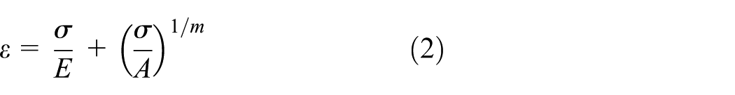
where

True stress-plastic strain of the material.
Smooth bar
Using ANSYS 14.5 with the large displacement option, detailed elastic–plastic, axisymmetric FEAs were performed to simulate the tensile tests of a smooth round specimen. Elements with a length of 0.01 mm were uniformly spaced in the minimum section. To simulate the necking behavior, dimensional deviation with a length of 0.01 mm in radius, a minimum value measured by the Vernier caliper, was chosen to construct the finite element (FE) model geometry, as shown in Figure 6(a).
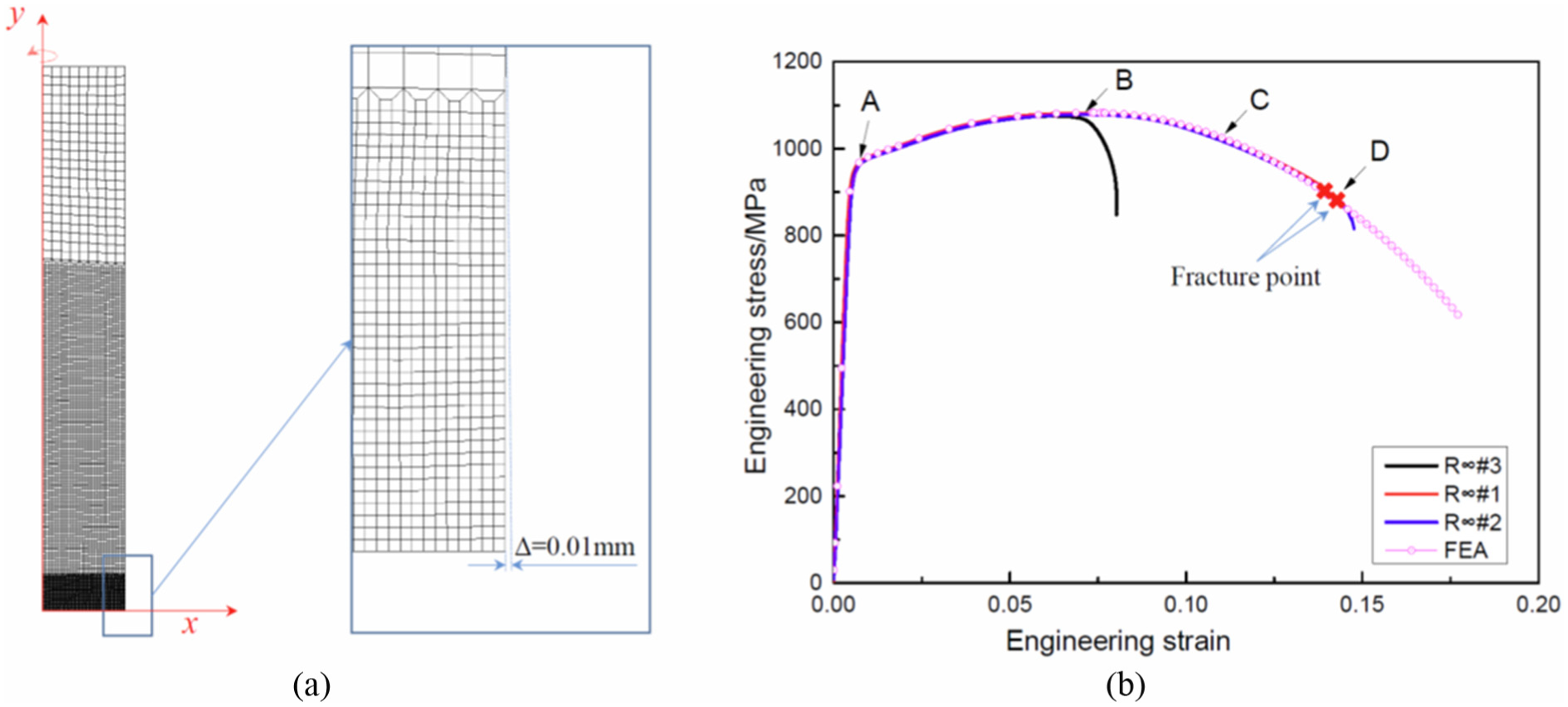
Numerical simulation of a smooth round bar: (a) FE model and (b) comparison between FE result and test data.
The engineering stress–strain curves extracted from the FE results were compared with the tensile test results, as shown in Figure 6(b). The comparison confirmed that the FE results are very well accorded with the test data, even after necking, except for specimen 3 because the necking region of specimen 3 is near the extensometer, thereby making the data useless. Figure 7 depicts the deformation and plastic strain response of a smooth round bar at different stages simulated via FE analyses. It can be seen that at the beginning, a uniform deformation stage is controlled, and the plastic strain in the bar remains nearly constant, as point A in Figure 6(b) in the engineering strain–stress coordinates and illustrated in Figure 7. When the engineering stress achieves its maximum value, the plastic strain becomes concentrated because localized necking occurred (see point B) and accelerated (point C). Finally, fracture occurs when the plastic strain at the necking region achieves a specific value (point D). Fracture could be identified as the point where the test data deviates from the FE results, as shown in Figure 6(b).

Deformation and plastic strain response of a smooth round bar under loading: (a) uniform deformation, (b) maximum necking, (c) localized necking, and (d) ductile fracture.
Furthermore, an error approximation was conducted to assess the mesh sensitivity. Figure 8 depicts the structural percentage error in energy norm parameter SEPC, the energy error normalized against the strain energy (more detailed by Zienkiewicz and Zhu) 28 of the FEA results through different mesh sizes. It can be concluded that elements with a length of 0.01 mm were sufficiently fine enough for the present purpose.

Error approximation of the FEA results with different mesh sizes.
Notched bar
Detailed elastic–plastic, axisymmetric FE analyses were also performed to simulate the tensile tests of a notched round specimen. All the FE results were compared with the tensile test results. The numerical simulation of the notched round bar with R = 5 mm are shown in Figure 9, and simulations of bars of R = 2.5 mm and R = 1 mm are shown in Figures 10 and 11, respectively. Fracture was identified as the point where the test data deviate from the FE results.

Numerical simulation of a notched round bar with R = 5 mm: (a) FE model and (b) comparison between FE result and test data.
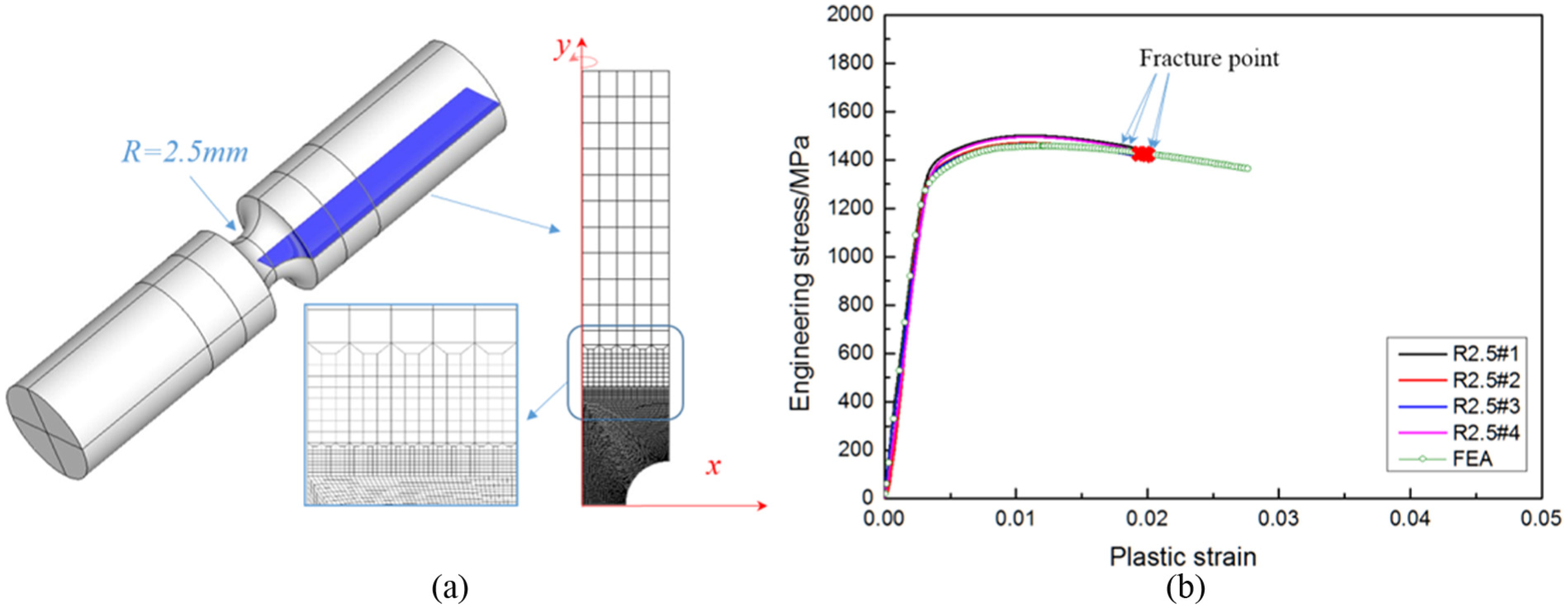
Numerical simulation of a notched round bar with R = 2.5 mm: (a) FE model and (b) comparison between FE result and test data.
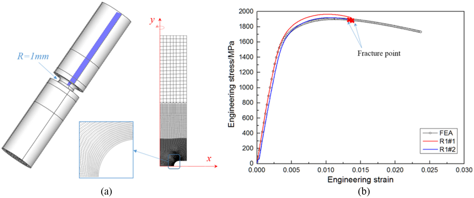
Numerical simulation of a notched round bar with R = 1 mm: (a) FE model and (b) comparison between FE result and test data.
Results and discussion
Distribution of stress and strain
The advantage of notched round bar tensile tests is to easily achieve different triaxiality conditions by merely changing the notched radius of the specimens. Typically, a semi-empirical analysis proposed by Bridgman
6
is used to approximately determine the local stress states of the notched region, in terms of the radius of curvature of the necking R, and the radius of the minimum cross section a, (see Figure 12) on the assumption that the equivalent stress


Stress states of a notched bar.
In this case, the triaxiality distribution of the notched bar can be determined according to the definition in equation (1)

In addition, the position of the maximum triaxiality can be found at the center of the notched bar
Because all of the FE results are in agreement with the test data, the FE results can be used to obtain the detailed stress–strain distribution of the specimens. The FEA results of the plastic strain and the triaxiality distribution along the diameter of the round bars at fracture are shown in Figure 13. The assumption of a constant plastic strain along the diameter by Bridgman is found not be true; instead, a slow change along the diameter is obtained from the FEA results. The predicted distribution of the triaxiality along the diameter by Bridgman, according to equation (7), also underestimates the true distribution compared with the FEA results.

Triaxiality and plastic strain of round bars along the diameter.
Fracture location
Many damage criteria have been proposed, postulating that fracture that occurs at a point in a body when the accumulated plastic strain reaches a critical value
where f(Tr) is a weighted function of triaxiality, and εf is the equivalent plastic strain to fracture.
The fracture location can be predicted using these damage criteria. To this end, the fracture surfaces of the specimens tested were first observed under a scanning electron microscope to identify the fracture initiation zone. As shown in Figure 14, both ductile and brittle fracture features were identified on the fractured notch surfaces. The ductile fracture can be identified by the presence of numerous micron scale cup and cones on the fractured surface and the brittle fracture by river-like patterns created by cleavage. It has been well established that ductile fracture is a precursor to brittle fracture, and the ductile fracture zone is considered to be the fracture initiation location.22,29,30 The fracture initiation locations were all situated at the centers of the specimens.

Fractographs of the specimens.
Effective triaxiality
Figure 15 shows the evolution of the plastic strain and the triaxiality obtained through FEA results in the entire range of deformation to fracture. It can be clearly seen that the triaxiality changes during the deformation, which makes it difficult to determine the effective value, especially for a smooth round bar, and the central triaxiality changes significantly from 1/3 at the beginning to almost 0.65 at fracture due to the intensification effect of the necking behavior.
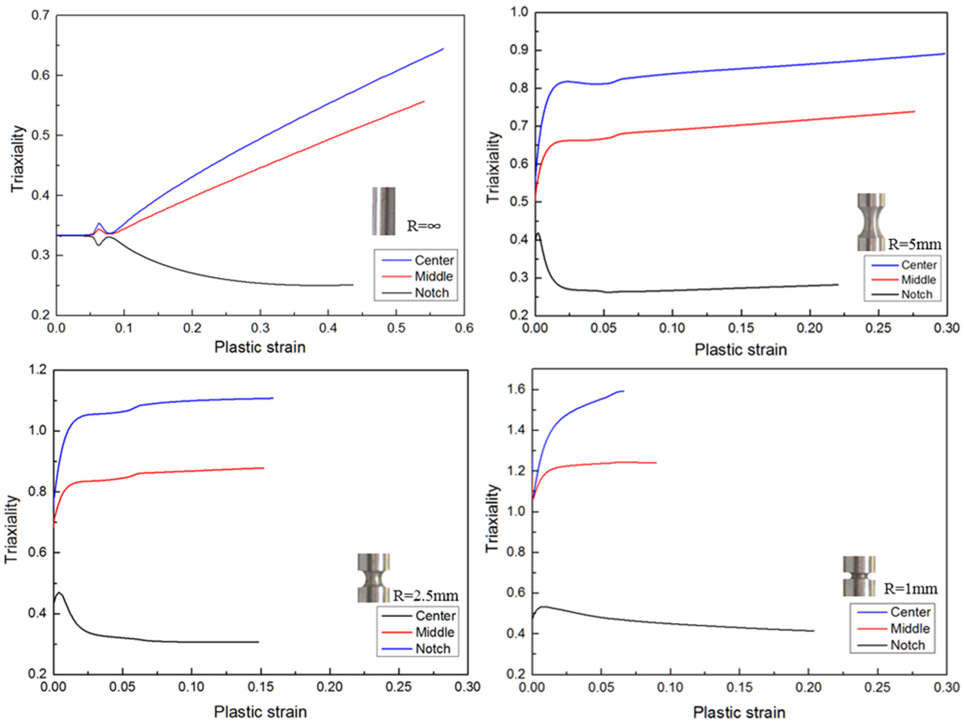
Evolution of the triaxiality versus the plastic strain during deformation predicted by FEA.
Rice and Tracey’s 7 exponential damage model was assumed in this article for its successful application in many research studies.17–21,23,24 Based on Rice and Tracey’s model, the effective triaxiality causing the equivalent damage was in the expression of equation (11) calculated from equation (10)


where A and B are material parameters,
There is a variable parameter B in equation (11), which cannot be used directly. Trial-and-error calculation should be performed with an initial value B = −1.5, which is the theoretical derivation by Rice and Tracey.
For simplification, an average triaxiality method proposed by Bao and Wierzbicki 17 has been commonly used to calculate the effective value

Obviously, equation (12) is based on a hyperbolic damage model

There is a deviation between equations (11) and (12). For clarity, an evolution of the plastic strain and the triaxiality with a linear relationship is assumed in Figure 16. The deviation of the effective triaxiality between these two equations in this case is 10%, and the deviation of the damage parameter D predicted through different methods is even higher.
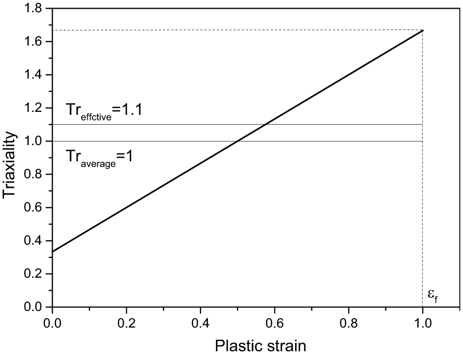
Comparison of the average triaxiality method and effective damage methods.
Fracture strain and limit
The effective triaxiality was calculated using equation (11) and the fracture strain criterion based on Rice and Tracey exponential damage model can be obtained as shown in Figure 17 and equation (14). It can be seen that equation (14) agrees with the test data and captures the dependence of the triaxiality on the fracture strain. For comparison, the average triaxiality calculated using equation (12) is also shown in Figure 17. The deviation between these two equations is very small in this case. Equation (12) is suggested for simplification when the triaxiality does not change significantly. However, deviation may occur especially when the triaxiality changes significantly in the loading history


Fracture criterion of PCrNi3MoVA.
Based on this equation, a damage evaluation was obtained as a function of plastic strain at the location of the center of each typical notched specimen mentioned above, depicted in Figure 18. It can be seen that the damage parameter at fracture point is around 1 for all specimens with different notches.

Evaluation of damage parameter with plastic strain.
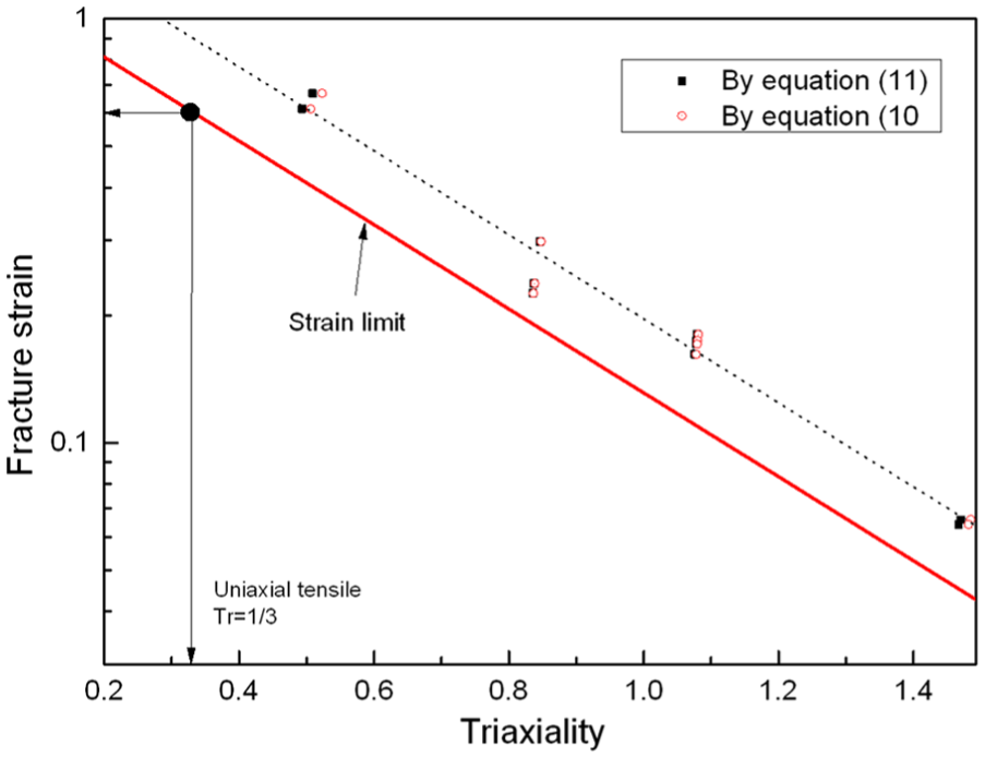
A minimum area reduction of 45%, accepted as a mandatory material requirement in the draft of the Chinese national standard of UHPVs, is conservatively considered as a fracture strain of 0.6 in the necking region calculated by equation (15) with a uniaxial tension stress state Tr = 1/3, as the point shown in Figure 19. Then, a strain limit based on the fracture strain criterion with the same exponent can be conservatively obtained as a lower bound of the test data, as shown in Figure 19 and equation (16). This strain limit has been accepted as a local failure criterion in the draft of the Chinese national standard for UHPVs made of gun steel


where
Strain limit in the draft Chinese national standard for UHPVs.
Plastic DBA method against local failure of UHPVs
With the strain limit obtained above, a new plastic DBA method protecting against local failure of UHPVs is introduced into the draft of the Chinese national standard for UHPVs. The design procedure is shown in Figure 20.

Design procedure to protect against local failure of UHPVs.
Conclusion
This article focused on the local failure of UHPVs, and detailed discussion on ductile fracture of gun steel PCrNi3MoVA developed for UHPVs was provided in this study. Tensile tests on a smooth round bar and notched bars with three different notch radius values were performed to determine the fracture strain as a function of different notched radius values, and detailed elastic–plastic, axisymmetric FE analyses were performed to estimate the variations of triaxiality during the tensile loading. The plastic fracture strain was obtained by combining the FE results with the experimental results. A fracture strain based on Rice and Tracey’s exponential damage model was obtained and a strain limit was proposed. Agreement between the FE results and the experimental results was found to be quite good, which validates the use of the proposed strain limit in the design procedure. A new plastic design-by-analysis (DBA) method was proposed into the design protecting against local failure of UHPVs.
Footnotes
Acknowledgements
Professor Jin-yang Zheng in Zhejiang University and Dr Zhi-wei Chen in the Chinese Standardization Committee on Boilers and Pressure Vessels gave substantial suggestions to the revision.
Handling Editor: Michal Kuciej
Declaration of conflicting interests
The author(s) declared no potential conflicts of interest with respect to the research, authorship, and/or publication of this article.
Funding
The author(s) disclosed receipt of the following financial support for the research, authorship, and/or publication of this article: This research was supported by the Special Funds for Quality Supervision Research in the Public Interest (“Research on Key Technologies for the Design Standard of Ultra-High-Pressure Vessels,” grant no. 201210242).