
Abstract
The dynamic characteristics of the mill and the drive system are mutually coupled and affected closed-loop system. However, most research has considered only the vibration of the drive system or the vibration of the mill to determine the cause of the accident in the equipment condition monitoring and fault diagnosis process. Condition monitoring and fault diagnosis based on this type of approach can lead to misdiagnosis or missed diagnosis in determining faults in actual systems. So, in this study, a dynamic model of the coupling between a mill and its drive system was developed to study the interaction of the mill and the drive system with the goal of increasing the accuracy of diagnostic methods and to improve the quality of the rolled material. A nonlinear coupling dynamic model was formulated to represent the relation between the gearbox vibration amplitude and various time-varying parameters to study the effects of various parameters on the drive system vibration characteristic under unsteady lubrication. Simulations results showed that increasing the strip speed, the input strip thickness, or the output strip thickness or decreasing the lubricating oil temperature or the roller radius caused the vibration amplitude of the drive system to increase. The vibration frequency caused by variations in the strip inlet or outlet thickness can be transmitted to the drive system, and gear meshing frequency of the gearbox can be transmitted to the mill. Test data from an actual cold rolling mill verified the accuracy of the model. The model was shown to be capable of simulating the mutually coupled and affected mechanism between a mill and its drive system.
Keywords
Introduction
With advances in the industry, the requirements for cold rolling mills in terms of strip yield and strip surface quality have become more stringent. In cold rolling mills, increasing the speed increases the yield, but the vibrations must be reduced to improve the quality of the product. High speeds increase vibrations and thus the probability of failure, which decreases the profitability of a mill. For example, in a cold rolling mill operated by Wuhan Iron and Steel Corporation (WISCO), a roller locked fault in the fourth stand caused a bolt that connects the upper and lower sections of the gearbox housing to break. The mill had to be shut down for 48 h, resulting in a loss of tens of millions of RMB and may have caused additional, undetected problems. Therefore, methods for reducing the failure rate and improving product quality and production efficiency are important to the industry.
One effective method to reduce equipment failure rates is through fault detection and diagnostics, namely, detecting anomalies and accurately determining the source of the problem at the early stages of a failure, taking effective interventions to prevent severe damage. However, the mill and its drive system are mutually coupled and affected closed-loop system. Thus, if the mill or the drive system develops a problem, it is very difficult to determine the source of the problem. Because the coupling mechanism between the two is not clear, making fault detection and diagnosis is difficult. Therefore, it is of great practical significance to study the nature of coupled vibration characteristic and failure mechanism in a cold rolling mill.
The mechanism of rolling mill vibrations has attracted significant attention from the research community. Various studies have investigated the mechanism of drive system vibrations. CY Gao et al. 1 studied torsional vibration in the main drive system of a mill with multiple clearances and simulated the dynamic response of a system with various clearances. The study also compared the effects of various types of simplified clearances on the dynamic response of the system and the torque amplification coefficient of each shaft section. In addition, the effects of the amount of clearance and the position on the system torque amplification coefficient were studied. SP Ming and LJ Zhao 2 studied the nonlinear dynamics characteristic for torsional vibration of the main drive system with various parametric excitations. He points out that the joint angle, damping coefficients, and nonlinear stiffness have a strong effect on vibration characteristics of the main drive system. Some scholars have studied the mill’s self-excited vibration characteristics, which consider the effects of different lubrication conditions and rolling parameters on the self-vibration and strip quality.3–5 XK Wang and H Lin 6 proposed an on-line measurement method for various guide modes of vertical ring rolling mill. YP Ding et al. 7 studied the effect of rolling speed on the mechanical properties and quality of strip. Y Kimura and N Fujita 8 studied the effect of lubrication on the tandem cold rolling mill. And a method is proposed to reduce the vibration of rolling mill by controlling the lubrication condition in high-speed rolling. Partial film lubrication characteristics of inlet zone in cold strip rolling have been studied by K Fu et al. 9 He simulated the influence of surface topography on the inlet film thickness and inlet zone length. The effect of the film thickness and surface roughness on the loads has been studied by K Dick and JG Lenard. 10 He pointed out that the roll roughness plays an integral role affecting the dependent rolling parameters during cold rolling of steel strips. As expected, an increased roughness leads to an increase in the rolling force on the rolling mill. An accurate dynamic model for the rolling process had been developed by PH Hu and KF Ehmann 11 based on the understanding of the unsteady lubrication mechanism. He studied the effect of the strip exit velocity on the rolling mill. N Fujita et al. 12 pointed out that the stability of the rolling mill decreases with the increase in the rolling speed, and through control, the friction coefficient can reduce the self-excited vibration. Compared with the model proposed by Hu, QY Wang and ZY Jiang 13 proposed a multi-factor coupling dynamic model of rolling mill. He studied the influence of main process parameters (the input or output strip thickness and the roller radius) on the critical speed and the amplitude of the vertical self-excited vibration of rolling mill.
Previous studies have focused on the vibration characteristic of only the drive system or the mill. Actually, the mill’s self-excited vibrations can affect not only the mill but also the drive system, and the vibration characteristic of the drive system can also affect the vibration characteristic of the mill. The vibration frequency from gear meshing in the drive system can affect the strip thickness at the entry or the exit or the oil temperature. The vibration frequency changes in the inlet or outlet strip thickness or the oil temperature can also affect the drive system and generate corresponding vibration frequency or sub-resonant frequency or frequency doubling in the gearbox. Therefore, developing a model of the coupling between a rolling mill and its drive system is very important. Such a model would not only allow the source of a fault in a cold rolling mill to be determined more accurately but also reduce misdiagnosis or missed diagnosis in fault detection that result from ignoring certain factors. Furthermore, the vibration of the mill can be determined indirectly, which avoids the problem of unreliable and discontinuous signals in the measurement of vibrations. This problem occurs because vibration sensors must be moved whenever the rollers are replaced, which occurs frequently. Therefore, the results of this study can be used to improve the effectiveness of fault diagnoses.
Coupling mathematical model of the mill
To study coupled vibrations in a cold rolling mill, a dynamic model of a 2800 cold rolling mill operated by WISCO was referenced. A simplified model of the mill, which includes a motor, a gearbox, and rollers, is shown in Figure 1.

14-DOF model of a cold rolling mill.
Model of the drive system
The drive system is composed of several components with inertia including the motor, the gearbox, and a coupler. The drive system transmits torque from the motor to the rollers and thus vibration characteristics in the drive system directly affect the surface quality of the rolled product.
Therefore, this article presents a model of 12-degree-of-freedom (DOF) lumped parameters drive system model. The following mathematical model of the drive system was used: assumed that the intermediate shaft is rigid shaft


where
Parameter values in the transmission system.

Model of rolling torque and rolling force in the mill with different rolling parameters
The dynamic rolling force in a mill is affected by multiple factors such as the thickness of the strip at the entry and the exit, the entry speed, the roller speed, the lubricating oil viscosity, the temperature of the emulsion (lubricant), and the roller radius. A mathematical model was developed to study the relation between various mill parameters and the rolling force, that is, to determine the changes in the rolling force caused by changes in the values of the various mill parameters. To simplify the calculations, the parameters were dimensionless in the equations relating each parameter to a rolling force variation coefficient. The rolling force variation coefficient is multiplied by the average rolling force to obtain the time-varying rolling force. The relations between each of the rolling parameters and the rolling force were studied. The derivation was as follows

where Mtv is the time-varying torque, Ftv is the time-varying rolling force,


where
Variations in the oil film thickness in the deformation zone play an important role in the change of rolling force. Thus, variations in the oil film thickness were modeled, and the effect of various rolling process parameters such as the rolling speed and the lubricant viscosity and concentration on the oil film thickness were investigated. The oil film thickness can be described with the relation shown in equation (16)


where

where


where the initial conditions for equation (20)
13
are
The preceding equations can be combined to derive an expression for the dynamic rolling force as a function of the time-varying parameters.
Model of mill and drive system coupling
The mill is connected to the drive system via a universal coupler, which the 2-DOF lumped parameters model between the mill and the drive system is shown in Figure 2. The rolling force and the torque are generated by the mill while in the process of rolling strip and transmitted to the gearbox by the coupler, thereby imparting a counter torque at the output of the gearbox. The torque at the output of the gearbox drives the mill. Therefore, the mill and the drive system are coupled, and equations (23) and (24) express the coupling relation


where

2-DOF dynamic model of the coupler between the mill and the drive system.
Equations (23) and (24) represent the coupling between the mill and the drive system and were used to study the coupled vibration characteristic. The rolling force and torque, which vary with time, are transmitted to the output of the drive system, and the output torque of the gearbox drives the mill. The dynamic response of the drive system can be obtained by solving the coupling equations.
Simulation of coupled vibrations of the mill and drive system
Effect of rolling speed on drive system vibration characteristic
To study the effect of the rolling speed on the drive system vibration characteristic using the coupling model, equations (13)–(15) were used to solve for the torque at the output of the gearbox. Equations (1)–(12), (23), and (24) were used to derive the amplitude of the gearbox vibration for different dimensionless rolling speeds. To simplify the calculations, the rolling speed was dimensionless as shown in equation (25)

where

Gearbox vibration amplitude under different rolling speeds.
Figure 3 shows that the dimensionless rolling speed had a significant effect on the vibrations of the gearbox. At low speeds (i.e. less than 0.8), the amplitude of the gearbox vibration remained nearly unchanged, but for dimensionless rolling speeds greater than 1, the amplitude increased dramatically with the rolling speed. Therefore, the greater the rolling speed, the more intense the gearbox vibration and the greater the amplitude. The noise also increased with the speed. Therefore, an appropriate rolling speed can be selected based on the amplitude of the gearbox vibration.
Effect of inlet strip thickness on drive system vibration characteristic
Changes in the inlet strip thickness cause changes in the rolling force of the mill and thus affect the vibration characteristic of the gearbox. The vibration characteristic of the gearbox with various inlet strip thicknesses was studied with all other parameter values held constant. An expression for the rolling force as a function of the inlet strip thickness can be derived using equations (14) and (15), and an expression for the gearbox output torque can be derived using equation (13). At some moment, the gearbox vibration amplitudes for various inlet strip thicknesses and the vibration spectrum can be derived using equations (1)–(12), (23), and (24). The relation between the inlet strip thickness and the gearbox vibration amplitude obtained from simulations is shown in Figure 4. The inlet strip can vary in thickness because of surface roughness and other factors. The variation in the thickness of the strip at the entry was modeled using a cosine function with a frequency of 60.99 Hz, as shown in equation (26)

where
Gearbox vibration amplitude under different inlet strip thicknesses.

Response diagram of gearbox with a time-varying inlet strip thickness: (a) time-domain diagram and (b) frequency-domain diagram.
Figure 4 shows the effect of inlet strip thickness on vibration characteristic of the gearbox. It can be seen that the gearbox vibration amplitude increased with increasing inlet strip thickness. Equations (12) and (13) indicate that the magnitude of the rolling force variation increased with increasing inlet strip thickness. The increase in rolling force fluctuation amplitude causes an increase in the reverse excitation at the gearbox output, resulting in an increase in the gearbox vibration amplitude. Figure 5 shows that the vibration frequency (60.99 Hz) caused by variations in the strip inlet thickness was transmitted to the drive system and caused a corresponding vibration frequency in the gearbox.
Effect of outlet strip thickness on drive system vibration characteristic
Changes in the strip thickness at the outlet lead to changes in the mill rolling force, and changes in the rolling force are transmitted to the gearbox by the coupler and thus have a major influence on the vibration and the fatigue of the gearbox. Equations (14) and (15) were used to derive an expression for the rolling force as a function of the outlet strip thickness. The gearbox output torque was calculated using equation (13). The gearbox vibration amplitudes for various outlet strip thicknesses and the gearbox vibration spectrum were derived using equations (1)–(12), (23), and (24). The relation between the outlet strip thickness and the gearbox vibration amplitude obtained from simulations is shown in Figure 6. There are variations in the outlet strip such as changes in the thickness and surface roughness. The variations in the strip thickness at the outlet were modeled using a cosine function with a frequency of 62.45 Hz, as shown in equation (27)

where

Gearbox vibration amplitude under different outlet strip thicknesses.
Response diagram of gearbox with a time-varying outlet strip thickness: (a) time-domain diagram and (b) frequency-domain diagram.
Figure 6 shows the effect of outlet strip thickness on vibration characteristic of the gearbox. It can be seen that the gearbox vibration amplitude decreased with increasing outlet strip thickness. Equations (10) and (11) indicate that the magnitude of the changes in the rolling force decreased as the strip outlet thickness decreased. Smaller variations in the rolling force result in less excitation at the gearbox output, resulting in smaller gearbox vibration amplitudes. Figure 7 indicates that the vibration frequency (62.45 Hz) caused by variations in the strip outlet thickness can affect the fluctuation characteristic of gearbox and caused a corresponding vibration frequency in the gearbox.
Effect of emulsion temperature on drive system vibration characteristic
Changes in the emulsion temperature during operation can cause changes in the viscosity of the emulsion and consequently cause changes in the rolling force. The relation between the temperature and the viscosity of the emulsion is given by equation (28).
14
Where we usually take the value as
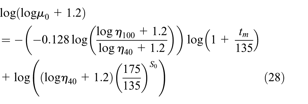
The relation between the emulsion temperature and emulsion viscosity can be obtained using equation (28). Through the joint solution of equations (18)–(22), the relation between the emulsion viscosity and the dimensionless film thickness can be obtained. The dimensionless oil film thickness obtained is used in equations (14) and (15) to derive a relation between the dimensionless film thickness and the rolling force. So, the relation between the emulsion temperature and the rolling force can be obtained. The rolling force obtained is used in equations (13) to derive a relation between the rolling force and the gearbox output torque. At some moment, equations (1)–(13), (23), and (24) were combined to solve the gearbox vibration amplitude under different emulsion temperatures and to obtain the vibration spectrum of the gearbox. The results of simulations are shown in Figure 8. Variations in the strip surface roughness, the rolling force, and other factors affect the emulsion temperature. The emulsion temperature was modeled using a cosine function with a frequency of 65 Hz. The maximum amplitude of the temperature changes was 10°C. The temperature model is given by equation (29)

where

Gearbox vibration amplitude versus emulsion temperature.

Response diagram of gearbox with a time-varying emulsion temperature: (a) time-domain diagram and (b) frequency-domain diagram.
Figure 8 shows the effect of oil temperature on vibration characteristic of the gearbox. It can be seen that the gearbox vibration amplitude decreased with increasing oil temperature. The reason is that an increase in the oil temperature causes the lubricant viscosity to decrease. And the decrease in lubricant viscosity causes the film thickness to decrease, resulting in smaller amplitude in the rolling force and thus a reduced excitation force in the tangential direction. These effects reduce the torque excitation acting on the gearbox and thus the gearbox vibration amplitude. Figure 9 indicates that the vibration frequency (65 Hz) caused by variations in oil temperature was transmitted by the coupler to the drive system and caused a corresponding vibration frequency in the gearbox.
Effect of roller radius on drive system vibration characteristic
Using equations (18)–(21), a relation between the dimensionless roller radius and the dimensionless oil film thickness was derived. The resulting expression for the oil film thickness was used in equations (14) and (15) to derive a relation between the roller radius and the rolling force. An expression for the gearbox output torque as a function of the roller radius was derived by substituting equation (14) into equation (13). Equations (1)–(13), (23), and (24) were combined to solve for the gearbox vibration amplitude as a function of the roller radius and to obtain the vibration spectrum of the gearbox. The relation between the roller radius and the gearbox vibration amplitude obtained from simulations is shown in Figure 10. The rollers are not perfectly round, so variations in the radius were modeled. The variations in the roller radius were modeled using a cosine function with a frequency of 60 Hz, as shown in equation (30)

where
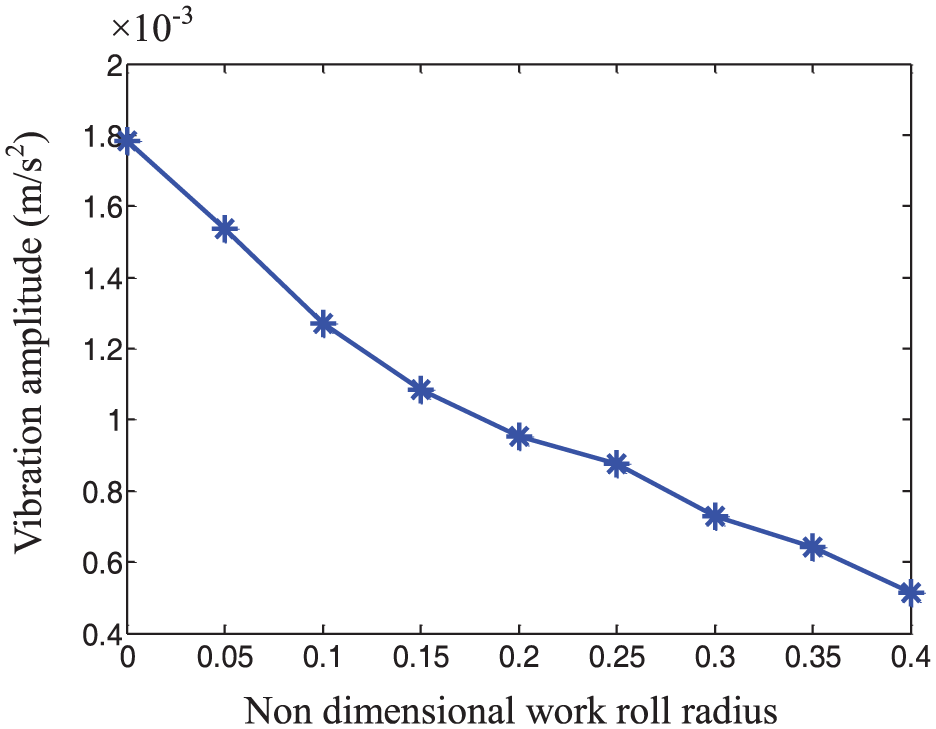
Gearbox vibration amplitude under different non-dimensional roller radii.

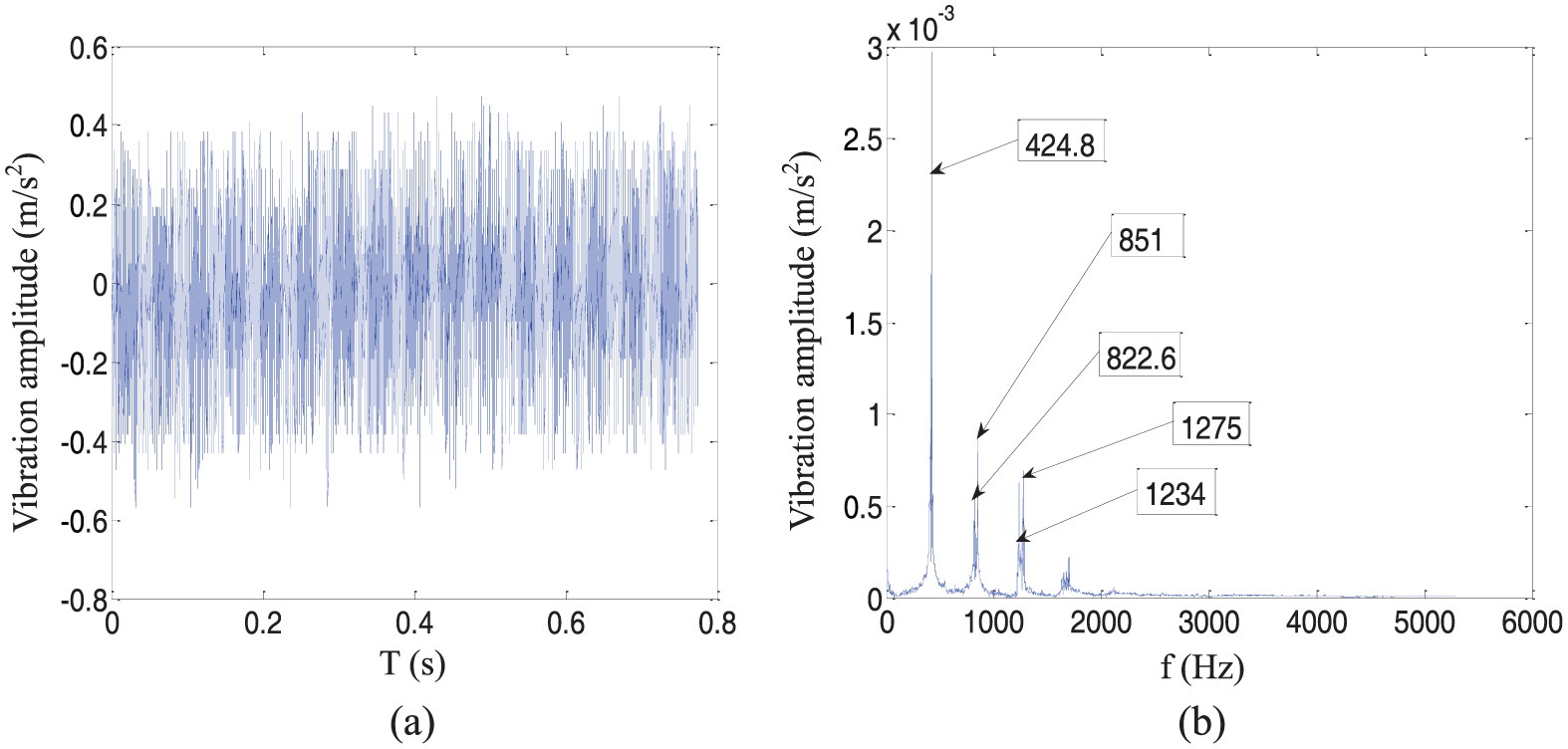
Response diagram of gearbox with time-varying roller radii: (a) time-domain diagram and (b) frequency-domain diagram.
Figure 10 shows that the gearbox vibration amplitude decreased with increasing dimensionless roller radius. The reason is that an increase in the roller radius causes the inlet oil film thickness to decrease, resulting in smaller amplitude in the rolling force and thus a reduced excitation force in the tangential direction. These effects reduce the torque excitation acting on the gearbox and thus the gearbox vibration amplitude. Figure 11 indicates that the vibration frequency (60 Hz) caused by variations in roller radius was transmitted by the coupler to the drive system and caused a corresponding vibration frequency in the gearbox.
Field verification of coupled vibration characteristic under various operating conditions
Vibration signals were taken from one of the cold rolling mills in the #2 plant of WISCO. Acceleration sensors were placed on the bearing at the output of the gearbox, as shown in Figures 12 and 13. The mill stand was monitored using Siemens online monitoring system, which measured the strip inlet thickness, the emulsion temperature, the rolling force, and the rolling speed, as shown in Figures 12 and 14. The drive system was monitored using a two-channel Emerson offline monitoring system with a sampling frequency of 2000 Hz and a sampling time of 1 s.
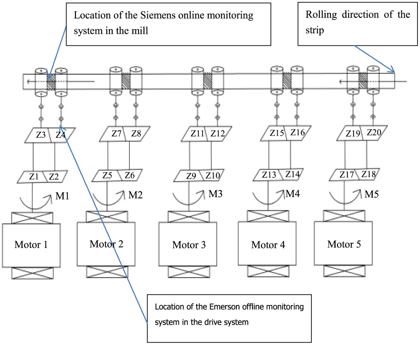
Diagram of the high-speed cold rolling mill.
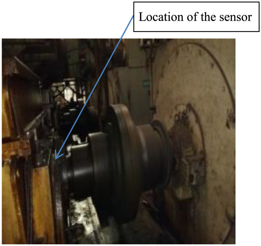
Location of sensors at the gearbox output.

Parameter monitoring and control interface for the mill.
Field verification of the effect of roller speed on the vibration characteristic of drive system
The on-line monitoring data of rolling mill and out-line monitoring data of the gearbox bearing were analyzed. With the other parameters held constant, the vibration amplitudes at the gearbox bearing for various rolling speeds were obtained. The actual values are shown in Figure 15.

Gearbox bearing vibration amplitude under different non-dimensional rolling speeds.
From comparison between Figures 3 and 15, it can be seen that the simulation results of the coupled model were consistent with the field measurement. For a dimensionless rolling speed greater than 0.5, the measured vibration amplitudes were slightly greater than the simulated values. The difference may be caused by the various field conditions: for rolling speeds greater than a certain level, various vibration sources are superimposed, resulting in slightly higher measured vibration amplitudes. However, the measurements verified the correctness and the validity of the coupling model.
Field verification of the effect of inlet strip thickness on the vibration characteristic of drive system
Vibration sensors were placed on the bearing at the output of the gearbox. The parameters were held constant using the mill control interface, and the vibration characteristics of the gearbox were measured for various inlet strip thicknesses. The measured values are shown in Figure 16. Figures 17 and 18 show the vibration spectrum diagrams of gearbox bearing in the vertical and axial directions, respectively, and Figure 19 shows the variation in the inlet strip thickness.

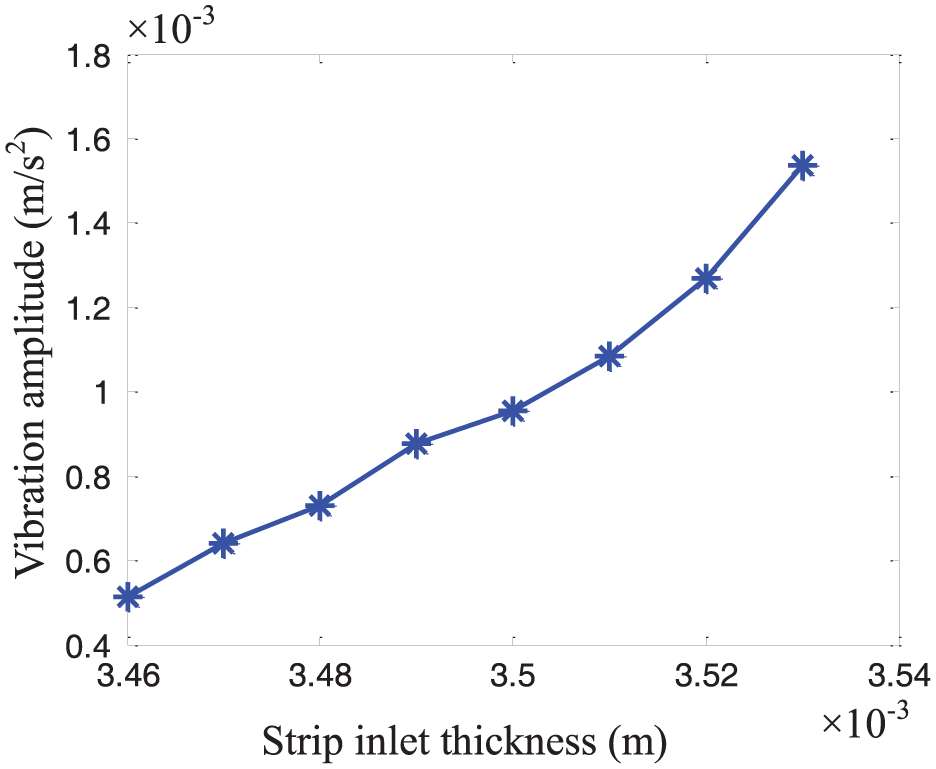
Gearbox vibration amplitude versus inlet strip thickness.

Gearbox vibration response diagram in the vertical axis under the time-varying strip inlet thickness: (a) time-domain diagram and (b) frequency-domain diagram.
Gearbox vibration response diagram in the axial direction for a time-varying strip inlet thickness: (a) time-domain diagram and (b) frequency-domain diagram.

Variation diagram in the strip inlet thickness: (a) time-domain diagram and (b) frequency-domain diagram.
From comparison between Figures 4 and 16, it can be seen that the simulation results were consistent with the field test data, demonstrating the accuracy of the model of gearbox vibrations as a function of the inlet strip thickness. In the diagrams of the vibration signals shown in Figures 17 and 18, the vibration at 60.99 Hz can be observed in the vertical direction of the gearbox but not in the axial direction. The excitation frequency from the variation in the inlet strip thickness was mainly at 60.99 Hz and its ½ sub-resonant harmonic. Therefore, we can conclude that these two frequencies caused by variations in the inlet strip thickness transmit to the gearbox. Because of the structure of the universal coupler, the excited vibration in the mill mainly affected the vibrations of the gearbox in the direction of vertical axis, whereas the axial vibrations were largely attenuated by the universal coupler. It can be seen from Figures 17 and 19 that the gear meshing frequency (424.8 Hz) of the gearbox was transmitted to the mill by the coupler and generated a corresponding fluctuation frequency in the spectrum diagram of the inlet strip thickness. The effect of the strip inlet thickness variation frequency (60.99 Hz) on the mill was also transmitted through the coupler to the gearbox and generated a corresponding frequency in the gearbox vibration spectrum diagram. A comparison of the spectra in Figures 4 and 5 with those in Figures 16, 17, and 19, which were obtained from the field test data, confirm the accuracy of the simulation model. These analysis results demonstrate that the mill and the drive system are mutually coupled and affected closed-loop system.
Field verification of the effect of outlet strip thickness on the vibration characteristic of drive system
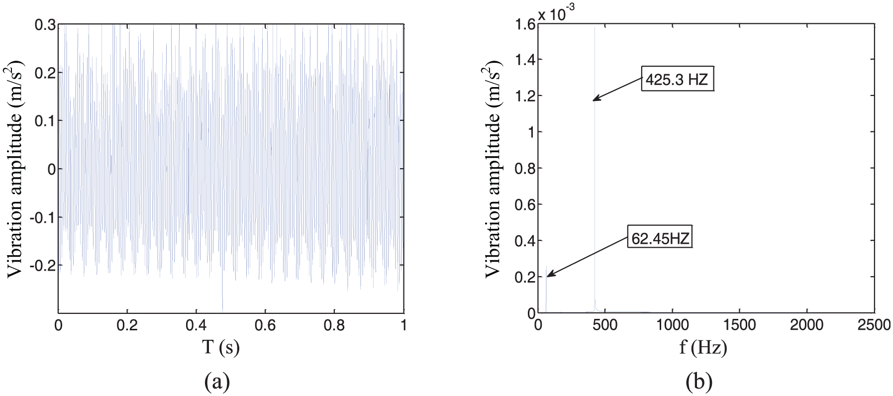
Vibration sensors were placed on the bearing at the output end of the gearbox in field test. With the other parameter values held constant using the mill control interface, the vibrations of the gearbox were measured for various strip outlet thicknesses. The measured results are shown in Figure 20. The vibration spectrum diagram of the gearbox bearing in the vertical directions is shown in Figure 21. Figure 22 shows the variation spectrum diagram in the outlet strip thickness.

Gearbox vibration amplitude under different strip outlet thicknesses.

Gearbox vibration response diagram in the vertical direction under the time-varying strip outlet thickness: (a) time-domain diagram, (b) frequency-domain diagram.

Variation diagram in the strip outlet thickness: (a) time-domain diagram and (b) frequency-domain diagram.
As shown in Figure 20, the gearbox vibration amplitude decreased with increasing strip outlet thickness. Compared with Figure 6, it can be seen that the simulation results were consistent with the measured data. The measurements verified the accuracy of the derived relation between the strip outlet thickness and the gearbox vibration amplitude. From Figures 21 and 22, it can be seen that the gear meshing frequency in the gearbox (425.3 Hz) was transmitted to the mill by the coupler and generated the corresponding frequency in the frequency spectrum of the strip outlet thickness. The strip outlet thickness variation frequency (62.45 Hz) of the mill was also transmitted through the coupler to the gearbox and generated a corresponding variation frequency in the frequency spectrum of the gearbox. A comparison of the spectra in Figures 20–22, which were obtained from the measurements, with those in Figures 6 and 7 verified the correctness of the simulation model, indicating the important practical significance of the coupling model.
Conclusion
A quantitative analysis was conducted on the effects of changes in various parameters of the rolling process in a cold rolling mill on the vibration of the drive system. Both the simulation model and measurements taken from an actual mill showed that increasing the rolling speed or the inlet strip thickness or decreasing the outlet strip thickness, the lubrication oil temperature, or the roller radius caused the vibration amplitude of the gearbox in the drive system to gradually increase.
The vibration frequency caused by variations in various parameters of the mill was transmitted to the drive system through the universal coupler and generated a corresponding vibration frequency at the drive system. The vibration frequency from gear meshing in the drive system was transmitted to the mill and caused variations frequency in various parameters. The measured data confirmed that the mill and the drive system are mutually coupled and affected closed-loop system. The analysis results verified the correctness and the usefulness of the coupling model. The coupling model provides a theoretical basis for further study.
This coupling model has very important practical significance. The model not only allows more accurate determinations of the source of a fault in a mill system, thus avoiding a misdiagnosis or a missed fault, but also indirectly detects vibration characteristic of the mill. Therefore, unreliable and discontinuous vibration signals in actual vibration measurements, which are caused by the necessity to move the vibration sensors each time the rollers are replaced, an event that occurs frequently, are avoided. Hence, the fault diagnosis is more effective.
Footnotes
Appendix 1
Academic Editor: Kai Bao
Declaration of conflicting interests
The author(s) declared no potential conflicts of interest with respect to the research, authorship, and/or publication of this article.
Funding
The author(s) disclosed receipt of the following financial support for the research, authorship, and/or publication of this article: This work was supported by the Natural Science Foundation of China (grant nos 51575007 and 51375019).