
Abstract
Before the natural gas pipeline was put into operation, nitrogen is usually used to replace the air in the natural gas pipeline. In order to prevent air and natural gas from forming explosive mixtures, it is necessary to study the mixing law in the displacement process. In this article, based on computational fluid dynamics basic theory and turbulence model theory, the mathematical model and boundary conditions of nitrogen replacement were determined. The nitrogen replacement process was simulated by Fluent software. The following conclusions are drawn from the analysis: (1) when the flow is laminar, the mixing length is longer than that of the turbulent state, so try to keep the gas in the turbulent state; (2) with an increase in the flow velocity, pipeline diameter, and pipeline length, mixing length increases; (3) with an increase in the back pressure, gas mixing length increases gradually, so try to avoid the presence of back pressure venting; (4) with an increase in the temperature, the mixing length increases gradually; (5) the formula for calculating the mixing length obtained by fitting is
Introduction
The earliest study of tracer convection in the tube flow is the British physicist GI Taylor, he used potassium permanganate aqueous solution as a tracer, did a diameter of 0.5–1.0 mm, length of 1520 mm pipe flow experiment, used the colorimeter to measure the axial concentration distribution. The disadvantage of this experiment is that he ignored the axial diffusion, only considered the radial diffusion, so that the experimental results obtained are not accurate enough.1–3 On the basis of Taylor’s experiment, Aris 4 took into account the influence of the axial diffusion, made up for the drawbacks of Taylor’s experiment, and thus obtained the laminar axial diffusion coefficient formula. In order to study the turbulent axial convection diffusion coefficient, the British physicist GI Taylor injected brine into the water using a straight pipe of 9.52 mm in diameter and 16.5 m in length in the experimental study. Due to the presence of brine, the conductivity of the solution has changed; the experiment for measuring the conductivity of the downstream solution reflected the concentration of brine and thus obtained the pipe turbulent diffusion coefficient formula.5–7
GH Qu and JG Liu 8 analyzed the replacement of the natural gas supply line from the first station of Pudong New Port to Beicai terminal. In this nitrogen replacement example, the pipeline used the style of segmented replacement and replaced by nitrogen. During the replacement process, the displacement is considered acceptable when the detection point indicates that the volume fraction of nitrogen in the mixed gas is greater than 98% (oxygen volume <2%) in the pipeline. When the nitrogen replacement qualified, should maintain the pipeline nitrogen pressure has slightly positive pressure, when the pressure reaches the nitrogen storage pressure 0.08 MPa, the pipeline can stop inject nitrogen. XX Sun and BX Liu 9 analyzed the adaptability of different displacement schemes, discussed the feasibility of the scheme without isolation pig, and qualitatively analyzed the data obtained from the tests. They obtained some general laws: (1) the efficiency of replacement without isolator is high; (2) the cost of replacement without isolator is low; (3) the replacement without isolator is safe and reliable. At the end of the study, it is concluded that it is feasible for nitrogen replacement of large diameter and long-distance natural gas pipeline to use the scheme without isolator.
According to the investigation of natural gas replacement, it can be seen that there is little research on the gas mixing law of nitrogen gas replacement, and no one has proposed the formula for calculating the mixing length of natural gas replacement. Therefore, this article, based on the computational fluid dynamics, used Fluent software to perform numerical simulation of the natural gas replacement process, obtained the law of mixing, and, finally, proposed a formula which can calculate the mixing length based on the simulation results.
Nitrogen replacement mathematical model
Establishment of model
Hypothetical condition
The process of replacing air with nitrogen is similar to replacing nitrogen with natural gas, so it is necessary to study the mixing process of nitrogen and air. To simplify the model, the simulation process assumes the following assumptions:
Ignoring the variation of pipeline radius, the whole pipe is regarded as equal diameter pipe;
The flow field and concentration field in the pipe do not change in the circumferential direction;
Air is a mixture of gases, considered as a single substance in Fluent simulation.
Control equations
1. Mass conservation equation
The continuity equation of two-dimensional unsteady flow in natural gas pipeline operation is given as

2. Conservation of momentum equation


where
3. Energy conservation equation


where
4. Component equation

where
Model equation
The applicable condition of the model k − ε is that the flow field is or can be approximated as a turbulent flow field.
k equation

ε equation
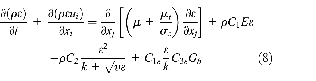


where k is the unit mass turbulent kinetic energy, m2/s2;
Basic parameters
Pressure
The pressure setting is very important in the numerical simulation and has great influence on the calculation results. In Fluent calculation, the first step is to set the operating pressure. In compressible flow with high Mach number, because the pressure varies greatly, it will not affect the accuracy of numerical convergence, and we can set the operating pressure as 0, which is equal to the absolute pressure gauge. In the compressible flow with low Mach number, the total pressure drop is small compared with the absolute static pressure, which will significantly affect the numerical convergence. In order to avoid this phenomenon, the operation pressure is atmospheric pressure in the numerical calculation.
Boundary condition
The inlet of nitrogen into the pipeline is set as the pressure inlet, and the outlet of the pipeline is set as the pressure outlet.
The boundary conditions also need to set the turbulence parameters, and the turbulence intensity is a characterization parameter of velocity fluctuation and the average flow velocity ratio. Generally, the turbulence intensity of less than 1% shows the low turbulence degree, and a high degree of turbulence needs the turbulence intensity to be greater than 1%. The hydraulic diameter is the physical quantity that the turbulent vortex is restricted when the turbulence is blocked by the obstacle, which is decided by the hydraulic diameter of the pipeline.
Initial condition
When setting the inlet boundary conditions, it is necessary to set the initial conditions of the gas in the pipeline. In the process of displacement, nitrogen concentration at pipeline inlet is 100%, and outlet nitrogen concentration is about 0.
Time step size
Fluent software for non-steady-state calculation, which is required to set the time step size and the maximum iterations per time step, for the pipeline, mainly depends on the length of time step.
Geometric model
In the process of replacement, because the flow field and concentration field in the pipeline are almost unchanged in the circumferential direction, the approximation is considered as a two-dimensional problem. Horizontal pipe and inclined pipe geometry models are shown in Figure 1.

Pipe geometry model: (a) horizontal pipe and (b) inclined pipe.
Grid division
High-quality mesh can effectively improve simulation accuracy, and grid quality standards are as follows: all or most of the grid lines are in parallel with the flow direction; all of the grid lines are substantially orthogonal; the grid lines at the wall area are substantially perpendicular to the wall. The boundary layer grid takes into account the boundary afforestation characteristics, making the solution more accurate than the uniform grid. In this article, the Quad-map mesh is used in the simulation process, grid partition as shown in Figure 2.

Grid division: (a) bend and (b) horizontal section.
Results and discussions
In order to study the law of gas mixing in the process of operation, the mathematical model of nitrogen replacement was established, and Fluent software was used to simulate the mixing law of air and nitrogen. Because the operation process only affects the total amount of injected nitrogen, it has no influence on the mixing law, and the influence of the operation process in the study of mixing law is not considered.
Based on diffusion theory and mass transfer theory, the theoretical formula for calculating the mixing length Lmix is deduced

where
According to equation (12), the mixing length is mainly affected by the gas velocity, the inlet and outlet pressure, the diameter of the pipeline, and the length of the pipeline. The purpose of this article is to study the general law of the mixing length during the replacement process, and the effects of different flow regimes, different inlet velocities, different pipeline lengths, different pipeline diameters, different pressures, and different temperatures on nitrogen displacement were studied.
Effect of flow regime on mixing length
Nitrogen displacement under two flow regimes was simulated, the distribution of nitrogen concentration in the same displacement length is compared, and the simulation results are shown in Table 1. The cloud diagram of nitrogen concentration is shown in Figure 3.
Gas mixing length in different flow regimes.


Cloud diagram of nitrogen concentration: (a) laminar flow and (b) turbulent flow.
The results in Table 1 and Figure 3 show that the mixing length of laminar flow is longer than that of the turbulent flow, and the displacement time is much longer than that of the turbulent state. This is because when the nitrogen displacement is in the laminar flow, the cross-sectional flow rate in the pipeline varies greatly, the velocity is about two times of the average speed, and the radial velocity gradient is large. As the average flow rate of laminar flow is small, it results in a laminar flow with not only the long mixing length, but also with the much longer replacement time than the turbulent state, which will extend the production cycle and reduce production efficiency. Therefore, during the replacement of nitrogen, the gas should be as far as possible in a turbulent state.
Effect of flow rate on mixing length
In order to study the effect of velocity, the pipe with different displacement lengths was replaced with different velocity under certain pipe diameter, and the mixing length was compared. The simulation results of 600, 800, 1000, 1200, 1600, 2000, 2400, 2800, 3200, and 4900 m pipe lengths at the speed of 3, 4, 5, and 7 m/s under the condition of diameter D = 1016 mm are shown in Figure 4 (in Figure 4, PL represents pipeline length).
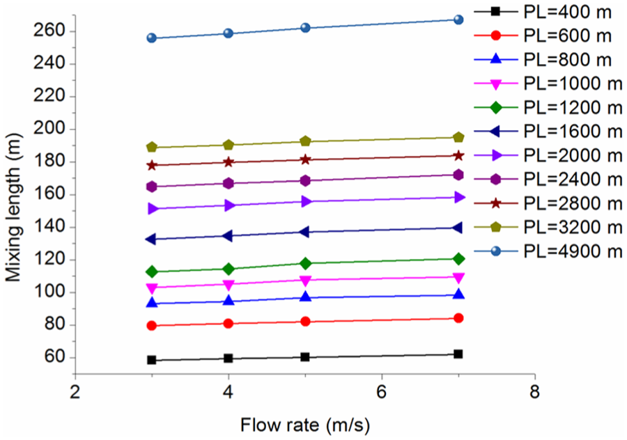
Gas mixing length under different flow rates with different pipeline lengths.
From Figure 4, following conclusions were obtained: mixing length is approximately linearly proportional to the flow rate, and with an increase in the flow rate, the mixing length gradually increases. Displacement speed cannot be too low because it will cause the tube flow in the laminar flow state, and form a large number of mixed gas, the mixing length will be increased, the replacement time will be extended, the replacement efficiency will be reduced. The replacement speed cannot be too large; although the replacement speed can effectively reduce the replacement time and improve the replacement efficiency, in the meantime, it will increase the mixing length. Therefore, combined with the above considerations, replacement rate should be controlled at 3–5 m/s.
Effect of back pressure on mixing length
In order to compare the effect of back pressure on the length of the mixed gas section, the pipeline with a length of 1 km and a pipe diameter of 1016 mm was simulated at different speeds at back pressures of 0 Pa (absolute pressure = 101,325 Pa), 20 kPa (absolute pressure = 121,325 Pa), and 50 kPa (absolute pressure = 151,325 Pa); the mixing lengths under different flow rates and back pressures were obtained, as shown in Figure 5.

Gas mixing length under different flow rates with different back pressures.
Figure 5 show that the presence of back pressure increases the mixing length; the greater the back pressure, the greater the mixing length. Therefore, the existence of back pressure during the natural gas pipeline replacement is unfavorable.
Effect of pipeline length on mixing length
Under the condition of same diameter, the pipelines with different lengths and different displacement speed were simulated: 400, 600, 800, 1000, 1200, 1600, 2000, 2400, 2800, and 3200 m pipe lengths at the speed of 3, 4, 5, and 7 m/s under the condition of diameter D = 1016 mm; the simulation results are shown in Figure 4.
It can be concluded that the longer the length of the pipeline, the longer the mixing length. With an increase in the pipeline length, mixing length growth rate gradually slowed down.
Effect of pipeline diameter on mixing length
In order to analyze the effect of pipe diameter on the mixing length, under the same conditions, the different diameters of nitrogen replacement were simulated. Displacement flow rate is 4 m/s and replacement lengths are 400, 800, 1200, and 1600 m; the simulation results are shown in Figure 6.

Gas mixing length under different pipeline diameters with different pipeline lengths.
As can be seen from Figure 6, the greater the diameter, the longer the mixing length; the growth rate of the mixing length increases as the diameter gradually decreases. This is because the mixing length mainly depends on the size of the cross-sectional area of the pipeline at a constant replacement rate.
Effect of temperature on mixing length
In the gas mixing length formula, although the effect of temperature is not clearly expressed, according to the gas state equation, it shows that the temperature has an impact on the flow of gas, especially the diffusion situation. A pipeline with 1 km length was used to simulate the influence of temperature on the mixing length and the replacement time. The displacement speed is 4 m/s, and the results are shown in Figures 7 and 8.
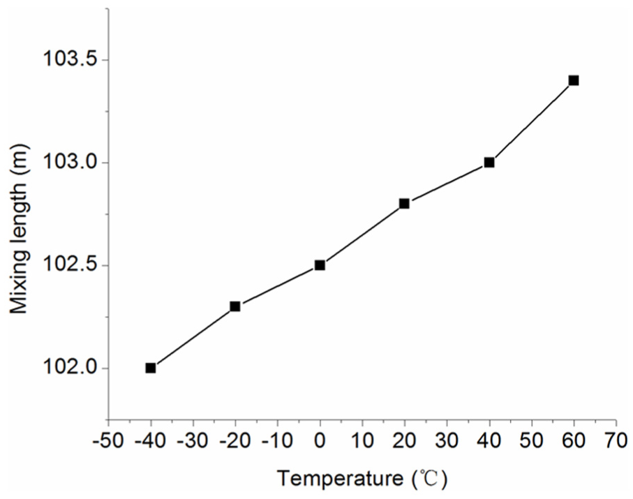
The effect of temperature on mixing length.

The effect of temperature on replacement time.
It can be seen from Figures 7 and 8 that the mixing length and displacement time increase with an increase in the temperature. Considering the mixing length and the replacement time, the temperature of nitrogen injection should be controlled at 5°C–25°C.
Formula for calculating gas mixing length of natural gas replacement
Formula fitting
Based on the data of numerical simulation, MATLAB was used to perform three-dimensional analysis, and the relationship between L/D, v, and Lm/D can be obtained (Figures 9 and 10).

Relationship diagram.

Curve fit graph.
The mixing length calculation formula is

where Lm is the mixing length, m; v is the replacement flow rate, m/s; L is the replacement length, m; D is the pipeline inner diameter, m.
Verification of formula
In order to make sure the reasonability of equation (13), a pipeline example was used to verify it. The length of a certain gas pipeline is 217 km. According to the diameter, the pipeline can be divided into two sections. The diameter is 1016 and 559 mm, respectively. Nitrogen pressure is 0.052 MPa, replacement time is 2 h, replacement flow rate is 6.67 m/s, and the final mixing length is 7 km. The mixing length calculated by equation (13) is 5.55–7.26 km; based on above-mentioned data, the calculation result can fit the site data. Therefore, equation (13) is reasonable.
Conclusion
In this article, the Fluent software is used to simulate the factors of the mixing length in the replacement process of natural gas pipeline. The main factors that affect the mixing length are flow regime, flow rate, back pressure, pipeline length, pipeline diameter, and temperature. Some conclusions can be obtained:
During the replacement of nitrogen, the gas should be as far as possible in a turbulent state.
In the replacement process, replacement rate should be controlled at 3–5 m/s.
The existence of back pressure during the natural gas pipeline replacement is unfavorable.
Considering the mixing length and the replacement time, the temperature of nitrogen injection should be controlled at 5°C–25°C.
The mixing length calculation formula is
Footnotes
Acknowledgements
The authors would like to specially acknowledge Lizhu Pu of Southwest Petroleum University.
Academic Editor: Jun Ren
Declaration of conflicting interests
The author(s) declared no potential conflicts of interest with respect to the research, authorship, and/or publication of this article.
Funding
The author(s) received no financial support for the research, authorship, and/or publication of this article.