
Abstract
For sine movable tooth drive, the movable tooth number must be increased to obtain large speed ratio of the drive which increases largely radial size of the drive. Here, a two-step sine movable tooth drive is proposed. For the drive, a small radial size and large speed ratio can be realized simultaneously. For the drive, three-dimensional design is done; the forces and the torque in the drive system are investigated; and changes in the output torque along with the main parameters are analyzed. Results show that the output torque of the two-step sine movable tooth drive is much larger than that of the single-step sine movable tooth drive. In the drive, the output torque fluctuation occurs. To reduce the output torque fluctuation, a large speed ratio, large axial amplitude of the sine ball tracks, and a reasonable speed ratio distribution should be used.
Introduction
Movable tooth drives have a lot of advantages such as high operating efficiency, simple structure, and small size. In 1980s–1990s, several types of the movable tooth drives were proposed.1–5 In 2006, Li et al. 6 did failure analysis of a sine ball tooth drive and laid basis for optimum of the ball tooth drive system. In 2009, Terada and Imase 7 investigated the motion principle of a two-stage type of the cycloid ball reducer and illustrated that the reducer has a constant velocity rotation characteristic in motion principle. In 2010, Terada 8 used the movable teeth drives in the robot joints and proposed the profile calculation method of the drives. In 2011, Liang et al. 9 established the tooth profile equation of the internal teeth ring for swing movable tooth drives and performed tooth profile synthesis and strength computation of the drives. In 2013, Nam et al. 10 designed and manufactured one thin plate-type speed reducer using ball teeth for robots, and the thin plate-type speed reducer imposed less compressive stress on the tooth profile and the balls, which greatly increased the facility of the robot. In 2015, Zhao et al. 11 derived the theoretical and actual profile equation of central wheel for a two-tooth difference swing-rod movable tooth transmission and analyzed the effects of parameters on the tooth profile of the central wheel. In 2015–2016, Xu and coworkers12,13 proposed an electromagnetic harmonic movable tooth drive system and an electromagnetic harmonic movable tooth drive system and investigated the output torque and free vibration of the drive system. Among above-mentioned movable tooth drives, the sine movable tooth drive has the smallest radial size and is suitable for oil drilling machine and robot arm and so on.5,6 However, for the sine movable tooth drive, the movable tooth number must be increased to obtain a large speed ratio of the drive. It increases largely radial size of the drive.
In this article, a two-step sine movable tooth drive is proposed. The drive can realize small radial size and large speed ratio simultaneously. For the two-step sine movable tooth drive, three-dimensional (3D) design is done; the forces and the torque in the drive system are investigated; and changes in the output torque along with the main parameters are analyzed. Results show that the output torque of the two-step sine movable tooth drive is much larger than that of the single-step sine movable tooth drive. Here, the torque fluctuation occurs. To reduce the output torque fluctuation, a large speed ratio, a large axial amplitude of the sine ball tracks, and a reasonable speed ratio distribution should be used.
Design of the drive system
Figure 1 shows the proposed two-step sine movable tooth drive. It consists of two single-step sine movable tooth drives integrated with each other.
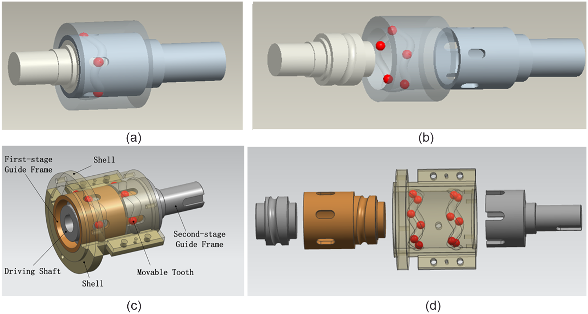
Sine movable tooth drive: (a) single-step drive, (b) installation of single-step drive, (c) two-step drive, and (d) installation of two-step drive.
The single-step sine movable tooth drive (see Figure 1(a) and (b)) consists of four basic elements: (1) the central input shaft on which an outer sine ball track with period number Z1 (here Z1 = 1) is produced, (2) the shell on which an inner sine ball track with period number Z3 (here Z3 = 5) is produced, (3) five balls: movable teeth, and (4) an output shaft on which guide slots for movable teeth are produced.
When the input shaft rotates, its outer sine ball track meshes with the balls, which meshes with inner sine ball track. When the shell is fixed, the balls drive output shaft by guide slots to rotate. If the input shaft rotates one circle, the output shaft will rotate Z1/(Z1 + Z3) circle. Thus, a reduction speed ratio i is given (here, i = 6).
To increase the reduction speed ratio, the period number Z3 of the inner sine ball track should be increased. Meanwhile, the movable tooth number should be increased as well. It will cause obvious increase in the drive size. To obtain a large reduction speed ratio and a small drive size simultaneously, we proposed an integrated two-step sine movable tooth drive.
The two-step sine movable tooth drive (see Figure 1(c)) consists of five basic elements: (1) the central input shaft on which an outer sine ball track with period number Z1 (here Z1 = 1) is produced; (2) the shell on which two rows of the inner sine ball tracks with period number Z3 and Z4, respectively, (here Z3 = 5 and Z4 = 5) are produced; (3) 10 balls: movable teeth; (4) the first-step output shaft on which guide slots for movable teeth and an outer sine ball track with period number Z2 (here Z2 = 1) are produced; and (5) the second-step output shaft on which guide slots for movable teeth are produced.
When the input shaft rotates, its outer sine ball track meshes with the first row balls which meshes with the first row inner sine ball track on the shell. When the shell is fixed, the balls drive the first-step output shaft by guide slots to rotate. The ball track on the first-step output shaft meshes with the second row balls which meshes with the second row inner sine ball track on the shell. As stated above, the shell is fixed so the second output shaft is driven to rotate by the second row balls.
If the input shaft rotates one circle, the output shaft will rotate Z1Z2/(Z1 + Z3) (Z1 + Z4) circle. Thus, a much larger reduction speed ratio i is given (here, i = 36).
Here, only 10 balls are required. If single-step sine movable tooth drive is used, 35 balls are required to obtain the reduction speed ratio of 36. The main parameters for the two-step sine movable tooth drive designed are shown in Table 1.
The main parameters for the two-step sine movable tooth drive.

Force and torque
A ball tooth is meshing with other elements (see Figure 2). Here, the center of the coordinate system is taken as the ball center, axis x is the radial direction, axis y is tangent direction, and axis z is axial direction. F1i denotes the force between the ball and the outer ball track of the input shaft, and αn1i denotes its directional angle. F3i denotes the force between the ball and the inner ball track of the shell, and αn3i denotes its directional angle. ui (i = 1, 3) denotes directional angle of the contact line between each mesh pair. F2i denotes the force between the ball and the guide slots.

Forces on the meshing elements: (a) movable tooth, (b) ball track on input shaft, and (c) ball track on shell.
From the force balance relation, it is known

In equation (1), there are five unknown parameters. So, two deformation coordination equations should be given.
Letting F1ix and F1iyz denote radial component and normal one of F1i, respectively, Δs denotes the tangent displacement of the balls under a given torque, the deformation coordination equation of the mesh pair is

where
From torque balance relation of the input shaft, we can give
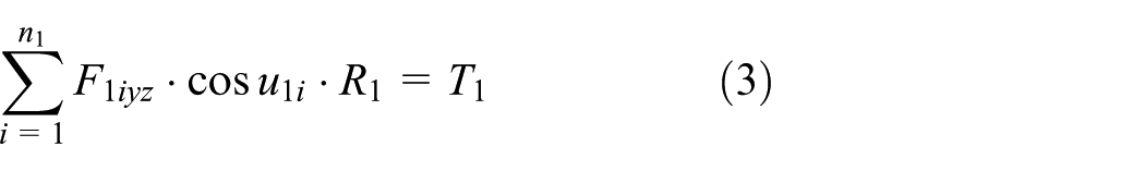
where T1 is the input torque, which equals to motor torque Tem. n1 is the ball number of the first-step drive.
From equations (2) and (3), it is known

Here
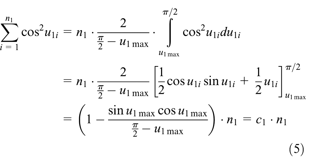
where
From equations (4) and (5)

From the geometric relation of the drive system, it is known

where r′ is the radius of the sine ball track and r is the radius of ball.
Combining equation (1) with equations (7) and (8)
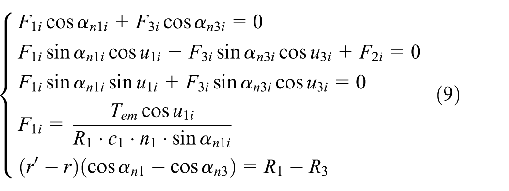
Using equation (9), five unknown parameters can be resolved.
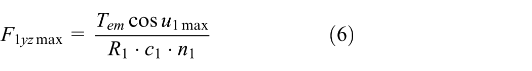
Among them, the force F2i is
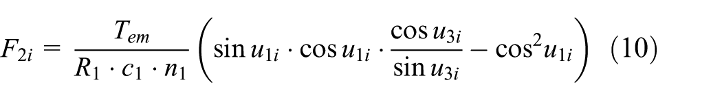
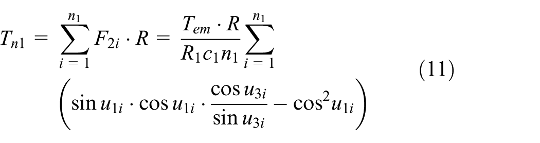
Thus, the output torque of the first output shaft can be given as
For the second-step movable tooth drive, in the same manner as deducing equation (9), following equation can be obtained

where

From equation (12)

Thus, the output torque of the second output shaft is

Results and discussion
Using above-mentioned equations, the forces in two-step sine movable tooth drive are investigated (see Figure 3). Here, upper figure is for the first-step drive and lower figure for the second drive. The main parameters of the drive are given in Table 1. The simulation is done for the rated input power (60 W) of the motor. Figure 3 shows the following:
In two-step sine movable tooth drive, the forces between the meshing elements change periodically. The time period of the force changes in the second drive is six times larger than that in the first drive which is identical to the reduction speed ratio between two steps of the drives.
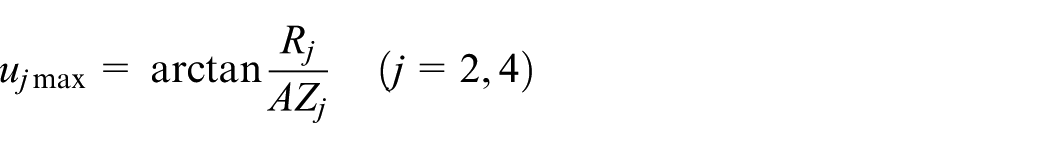
For the first-step drive, the time period of acting forces between the meshing elements is
For the second-step drive, the time period of acting forces between the meshing elements is
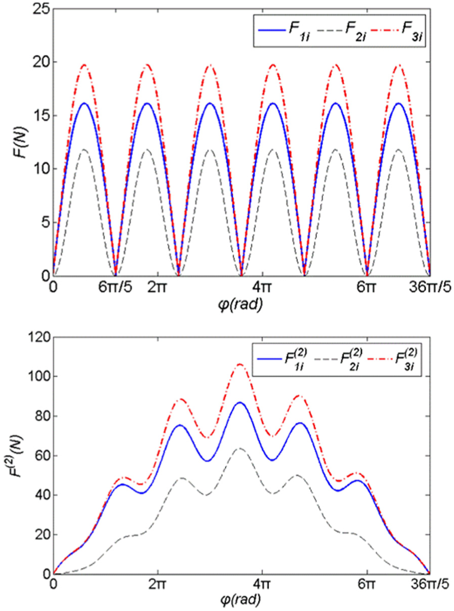
Forces in two-step sine movable tooth drive.
Using above-mentioned equations, the torques of two-step sine movable tooth drive are investigated (see Figure 4). Here, Tem denotes input torque of the motor, Tn1 denotes the output torque of the first-step drive, and Tn is the output torque of the second-step drive. Figure 4 shows the following:
The output torques of two-step sine movable tooth drive change periodically when input torque of the motor is constant. Similar to changes of the forces, the time period of the torque changes in the second drive is six times larger than that in the first drive.
For the first-step drive, the time period of output torque is still
For the second-step drive, the time period of output torque is still

Torques of two-step sine movable tooth drive.
To reduce the output torque fluctuation of the drive system, the period number Z3 and Z4 of the inner sine ball tracks are changed. Taking Z3 = Z4 = 3, 5, and 7, corresponding speed ratio is 16, 36, and 64. Other parameters are constant. Here, A = 3.6 mm, R = 25.5 mm, r = 4 mm, and r′ = 4.4 mm. Changes in the output torque fluctuation of the drive system are shown in Figure 5.
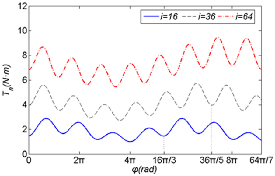
Changes in the output torques along with speed ratio.
As the period number Z3 and Z4 of the inner sine ball tracks increase (speed ratio increases), the average output torque of the drive system increases significantly and the torque fluctuation decreases significantly. At i = 16, the maximum output torque is 2.89 N m. The average output torque is 1.86 N m, and the fluctuation ratio is about 55%. At i = 64, the maximum output torque is 9.45 N m, the average output torque is 7.32 N m, and the fluctuation ratio is about 29%.
Under the condition that the speed ratio of the drive system is constant, the output torque fluctuation can be improved with tuning the speed ratio distribution of two-step drives. When the total speed ratio is 36, the speed ratio distribution of 4 × 9, 6 × 6, and 9 × 4 can be used. The torque fluctuation for the situation of the speed ratio pairs of 6 × 6 is given above. Here, the torque fluctuation for the situation of the speed ratio pairs of 4 × 9 and 9 × 4 is calculated (see Figure 6).

Changes in the output torques along with speed ratio pairs.
When the speed ratio of the first-step drive is taken to be larger than that of the second-step drive, the average output torque of the drive system increases significantly and the torque fluctuation decreases significantly. For the situation of the speed ratio distribution of 4 × 9, the maximum output torque is 3.09 N m, the average output torque is 1.82 N m, and the fluctuation ratio is about 70%. For the situation of the speed ratio distribution of 9 × 4, the maximum output torque is 11.73 N m, the average output torque is 9.27 N m, and the fluctuation ratio is about 27%.
For the situation of the speed ratio distribution of 9 × 4, the average output torque of the drive system is five times larger than that for the situation of the speed ratio distribution of 4 × 9. The fluctuation ratio of the output torque is improved about two times as well.
When two-step speed ratio is constant, the torque fluctuation as a function of the axial amplitude A of the sine ball track and the motion radius R of the sine ball tracks is investigated (see Figure 7; here, R1 = R3 = R).

Torque fluctuation as a function of A and R: (a) A changes and (b) R changes.
As the radius R of the sine ball tracks increases, the maximum output torque and the average output torque of the drive system increase, but the fluctuation ratio does not change nearly. For R = 20.5 mm, the maximum output torque is 4.89 N m, the average output torque is 3.42 N m, and the fluctuation ratio is 39.9%. For R = 30.5 mm, the maximum output torque is 6.57 N m and the average output torque is 4.70 N m, but the fluctuation ratio is still 39.9%.
As the axial amplitude A of the sine ball tracks increases, the maximum output torque and the average output torque of the drive system increase, and the fluctuation ratio decreases. For A = 3.6 mm, the maximum output torque is 5.75 N m, the average output torque is 4.11 N m, and the fluctuation ratio is 39.8%. For A = 13.6 mm, the maximum output torque is 6.02 N m, the average output torque is 4.33 N m, and the fluctuation ratio is 39.0%.
In a word, to increase output torque of the drive system, a large speed ratio, large axial amplitude A, and large radius R of the sine ball tracks should be used, and the speed ratio of the first-step drive should be taken to be larger than that of the second-step drive. To reduce torque fluctuation of the drive system, a large speed ratio and large axial amplitude A of the sine ball tracks should be used, and the speed ratio of the first-step drive should be taken to be larger than that of the second-step drive as well.
In order to illustrate above analysis, a model machine of the two-step sine movable tooth drive is designed and produced. Here, the most difficultly produced element is shell on which there are two rows of the inner sine ball tracks to be produced. The inner sine ball tracks are formed with a forming cutter on a three-axis numerical control (NC) machine tool (see Figure 8). For convenient installation of movable teeth, the shell is designed into a mounting body consisting of two half shells. The two half shells are positioned by two pins and linked by four bolts. The inner sine ball tracks on two half shells are formed simultaneously as a whole. Tool path is picked up automatically by the NC machine tool based on 3D model of the shell. To avoid meshing interference between two-step movable tooth drives, position accuracy (includes axial and tangent ones) between two inner sine ball tracks must be ensured strictly.

Shell and its manufacture for the two-step sine movable tooth drive: (a) forming inner sine ball tracks and (b) shell produced.
The main parameters of the model machine are the same as given in Table 1. Photographs of the model machine are given in Figure 9(a). Figure 9(b) shows its test apparatus. It includes the model machine, a dynamometer, a matched measuring instrument, and its drive system. The load torque can be given with the hysteresis dynamometer and the rotating speed is tuned with the frequency converter, and the load torque, the speed, and the power can be measured by measuring instrument.

Photographs of the model machine and its test apparatus: (a) model machine plus motor and (b) test apparatus.
With the frequency converter, the speed of the motor is tuned to 1680 r/min. With the hysteresis dynamometer, the load torque of the drive is increased gradually by adjusting control current of the hysteresis dynamometer. At the same time, the drive power is monitored. When the drive power gets to 60 W, which is the rated power of the motor, the corresponding load torque is recorded. It is just the rated load torque of the drive system.
Test results show that the output torque of the model machine is equal to 4.04 N m at rated input power (60 W). It is near to the average value (4.14 N m) of the output torque for the same parameters in Figure 7. The relative error between the simulating and measuring results is 2.5%. The results show that the equation of the output torque deduced in this article is sufficiently accurate and can be used to calculate load-carrying ability of the drive system.
In order to illustrate fluctuation of the output torque for the drive system, a precise photoelectric encoder is used to measure fluctuation of the output speed (here, the time interval between two adjacent data is 2 ms). It is because measuring the fluctuation of the output torque is difficult, and the fluctuation of the output speed can reflect fluctuation of the output torque. When the output torque is large, the output speed is low. Measured results are given in Figure 10. Here, rotating speed of the motor is 1680 r/min.

Output speed as a function of the time: (a) measured output speed and (b) fitted output speed curve.
The time for rotating 36π/5 of the input shaft is 0.128 s (it is the calculative time period of the output torque fluctuation). Here, the output speed fluctuation data for six times of the calculative time period are picked up (see Figure 10(a)). To see the fluctuation of the output speed in the model machine clearly, the measured data in Figure 10(a) are fitted (see Figure 10(b)). The fitted speed fluctuation curve is obtained by MATLAB software based on 384 measured data. From Figure 10(a) and (b), the following can be known.
The output speed for the drive system fluctuates periodically, and six speed peaks and six speed troughs occur here. It means that the speed changes through six time periods. The six time periods of the speed fluctuation correspond to six time periods of the torque fluctuation. It is because the speed increases when the load torque decreases under a given motor power. Therefore, six time periods of the speed fluctuation illustrate existence of six torque time periods. The results can illustrate analysis about fluctuation of the output torque for the drive system.
Conclusion
In this article, a two-step sine movable tooth drive is proposed. The drive can realize small radial size and large speed ratio simultaneously. For the two-step sine movable tooth drive, 3D design was done; the forces and the torque in the drive system were investigated; and changes in the output torque along with the main parameters were analyzed. In this article, the following conclusions can be obtained:
The output torques of two-step sine movable tooth drive change periodically when input torque of the motor is constant. For the second-step drive, in one time period of the output torque changes, several small output torque peaks occur because of the output torque changes in the first-step drive.
To reduce the output torque fluctuation, a large speed ratio, large axial amplitude of the sine ball tracks, and a reasonable speed ratio distribution should be used.
Footnotes
Academic Editor: José Tenreiro Machado
Declaration of conflicting interests
The author(s) declared no potential conflicts of interest with respect to the research, authorship, and/or publication of this article.
Funding
The author(s) disclosed receipt of the following financial support for the research, authorship, and/or publication of this article: This project was supported by the Hebei Province Natural Science Foundation in China (No. E2017203021).