
Abstract
The high quality of polished end face of photonic crystal fiber has a significant effect on coupling efficiency when photonic crystal fiber is used to couple with other optical devices. In order to obtain the smooth surface of the photonic crystal fiber, the end face polishing process of the photonic crystal fiber is analyzed using the finite element method in this article. Because there are many small air holes in the cladding of photonic crystal fiber, it needs better processing technology than that of ordinary fiber. The formation mechanism of cracks and the effects of cutting depth and grit tip radius on the processing results are researched, and this process is simplified as a single grit cutting a single hole wall and the cutting depth of grit with different diameters under certain lapping force is obtained by theoretical analysis. The simulation results show that finite element method can effectively simulate the end face lapping process of photonic crystal fiber, and that in the polishing process of photonic crystal fiber, the edge of hole wall is prone to the collapse area which is distributed along the circumference; cutting force and collapse area increase with the cutting depth and grit tip radius. For no collapse area generation, the maximum cutting depth of this photonic crystal fiber is less than the critical cutting depth of brittle plastic transition of ordinary fiber.
Introduction
Photonic crystal fiber (PCF) has a bright outlook for the areas of communication, sensor, biomedicine, and so on1,2 because of its various advantages such as endless single-mode propagation, a large single-mode area, and an unusual dispersion. When PCF is used to be coupled with other optical devices, its end face needs to be polished to obtain a smooth surface for a low loss and high coupling efficiency. 3 But there are many air holes in the cladding of PCF, which is different from the conventional single-mode fiber that has a solid and continuous end face. This discontinuous structure makes PCF end face easily broken, so it needs much stricter processing condition than that of conventional fiber. Now, recent research of optical fiber end face polishing mainly focuses on the ordinary fiber; 4 the study of PCF end face polishing is rarely reported.
The PCF is made by the high-purity quartz glass with stacking, drilling, and milling method. The quartz glass belongs to the typical hard-brittle materials so that it is very easy to have the brittle fracture causing the micro cracks during polishing process. While it verifies that the ductile regime processing to the quartz glass and other hard-brittle materials can be implemented with the no-crack and smooth surface within a certain cutting depth through the experiment made by Bifano et al., 5 and this certain cutting depth is called the critical cutting depth. Based on the experiment results, Neauport et al. 6 and Blaineau et al., 7 etc. study factors that influence the ductile regime processing of the quartz glass, such as the size of grit, cutting load, and cutting speed.
Generally, the polishing depth scale is about micrometers and nanometers, so the experimental method is not only time-consuming and laborious but also difficult to make the real-time observation during processing. While the simulation can display clearly the change of material surface and even the interior stress, strain, and so on, this is convenient to research on the removal mechanism of the material. At present, there are two common methods, the molecular dynamics (MD)8,9 and the finite element method (FEM),10–13 for the simulation analysis of polishing process. The MD relies on the potential energy function and is limited to the existing calculating ability of computers, and the simulation model is in nanoscale. In contrast, the FEM can model with a greater scale and currently, so in this study, we use FEM to simulate the end surface polishing process of PCF.
The finite element software usually has two numerical integration methods to the solution of the mechanical problem: the implicit method and the explicit method. The stability of the implicit integration method is unconditionally steady. The implement of converge through the global approximation needs repeated iterations which easily accumulates the error though with less calculation. Therefore, it only suits to the solution of the static and quasi-static mechanical problem. The characteristic of the explicit method is conditional stability without the iteration, and this method is suitable to the solution of the complex dynamic collision problem. 14 Now, the general analytic software of the explicit dynamics is the LS-DYNA developed by the LSTC Company.
Based on the explicit dynamics analytic software LS-DYNA, this article first verifies that the FEM can effectively simulate the removal process of the glass in the scratching process, including carrying out the simulation of the single hole wall and the single grit polishing process, analyzing the generating process of the crack and the effect of the polishing depth and the tip radius of the grit on the polishing result, obtaining the critical polishing depth which has no harm to the PCF, and providing the theoretical basis to the end face polishing processing of the PCF.
Materials and methods
Simulation algorithm
In the FEM analysis of the grit cutting process, the key point is the formation and removal of the material chips, which closely relates to the element algorithm of the finite element model. Two common finite element algorithms are the Euler algorithm and the Lagrange algorithm, 15 respectively. The Euler algorithm, however, has a fixed spatial grid and the material flows in the grid; therefore, it cannot describe the cutting process exactly. While the grid described by the Lagrange is combined with analyzed material, and the finite element node is fixedly connected with the material node. Therefore, the geometrical change of the material is consistent with the change of the finite element grid, and the material cannot flow between elements. It is precise to describe the movement of the structure boundary. 16 Hence, the simulation of the grit cutting along the end surface of PCF uses the Lagrange algorithm.
For the FEM, the matrix of the motion equation is

where
LS-DYNA uses the explicit central difference method to solve the motion equation. If the solution of 0,…,

where

The velocity and displacement at time


where
Geometric model
The polishing process can be considered that many grits, like cutting tools, cut the workpiece, and these cutting tools have very small geometric sizes. In the simulation, the geometric model of the grit is often simplified as a sphere, truncated cone, or cone. The grit in this article is simplified as the cone with a blunt tip.
In this study, we select the solid polarization-maintaining PCF fabricated by Fenghuo Company with 1550 nm operation wavelength to build the model. The scanning electron microscope (SEM) photo of this fiber end face is shown in Figure 1(a).
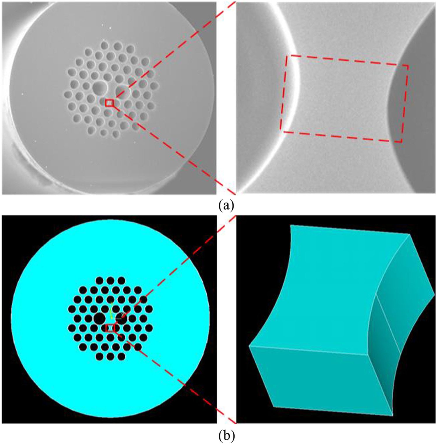
PCF real model and geometric model: (a) SEM photo of PCF end face and hole wall and (b) the geometric model of PCF end face and hole wall.
The diameter of the solid polarization-maintaining PCF is about 95 µm, the large air hole diameter is 7.3 µm, the small air hole diameter is 4 µm, and the thinnest wall of hole between small air holes is about 1.2 µm. For the convenience of the study and saving the computing time, it only selects the thinnest wall between small holes to build the geometric model, as shown in Figure 1(b), with model height of 1 µm, thickness of 1.6 µm, and spacing of two arcs of 1.2 µm.
Both the geometric model of air hole wall and grit are symmetrical structures; therefore, we make half of them to simulate for reducing the simulation time. The contact area between grit and air hole wall has been finely meshed, and the mesh size in other areas is relatively coarse; hence, we obtain the finite element mesh model of PCF polishing, as shown in Figure 2. Meanwhile, the cone angle of grit is 90°, the radius of blunt tip is R, for the fiber’s element size, refined part size is 10 nm, coarse part size is 20 nm and element number is 540,000.

PCF polishing finite element mesh model.
Material model
Setting up a material model is the constitutive description of the material, stress–strain relationship of material under different conditions, and is also important for the FEM simulation. The fiber material is quartz glass, a typical hard–brittle material. To precisely reflect the dynamic response problem during glass polishing process, we select Johnson–Holmquist (JH-2) ceramics in LS-DYNA as glass material model, and this model is widely used in the dynamic simulation of the hard–brittle material.18,19
In the JH-2 model, the equivalent stress strength of the material is

where D is the material damage parameter


where
All the normalized strength
where
The material damage parameter D is defined as

where

where

where
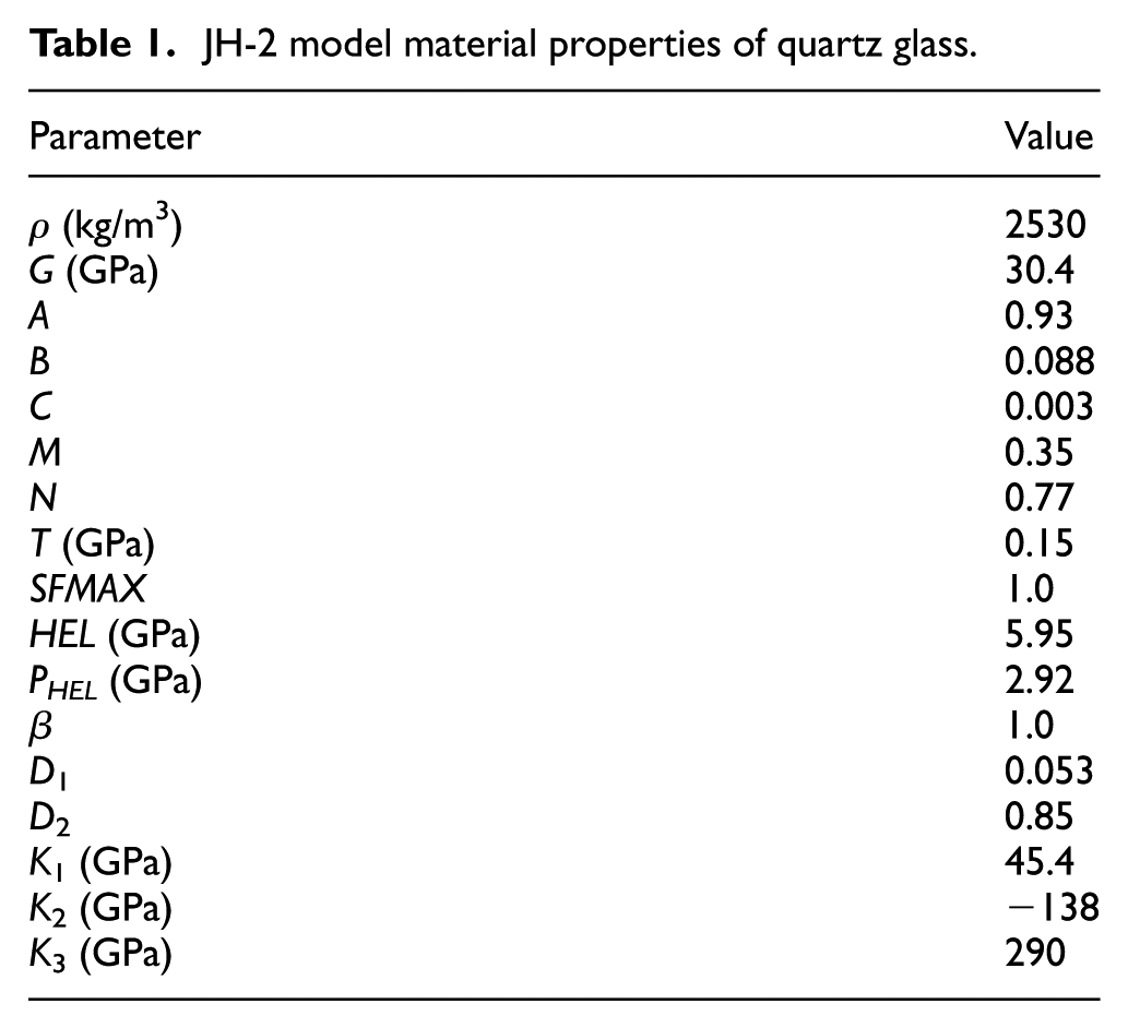
The quartz glass material properties of JH-2 model 20 are shown in Table 1.
JH-2 model material properties of quartz glass.
The grit material is silicon carbide which has almost non-deforming during the polishing process. So the grit is supposed to rigid body. The grit material properties are shown in Table 2.
Silicon carbide material properties.

Boundary conditions and simulation parameters
As shown in Figure 2, it can be seen that the grit cuts fiber end face along the minus direction of X-axis; symmetric plane of the whole model is in the X-Z plane; and direction of cutting depth is parallel to Z-axis. In a real experiment, the fiber is put in a thin glass tube and stuck in wax first and then the glass tube is mounted on a holder. Otherwise, the fiber is much longer than the FEM model in this article, so we use full constraints on the bottom of fiber. Because both the hole wall and grit are symmetrical, we build a half model and use symmetrical constraints on the symmetrical plane. Symmetry constraint is put on the symmetric plane of fiber and grit. Non-reflection constraint is put on the back side of fiber to avoid the reflection of stress wave at this boundary. According to the experimental parameters in Table 3, simulations are conducted in different conditions.
Simulation parameters.

Results
Simulation experiment of glass scratching
To better understand the cutting mechanism of hard–brittle material, many researchers have made deep study into the scratching process.21–24 Duan et al. 25 use FEM and smoothed particle hydrodynamics (SPH) coupling algorithm to complete the simulation of single grit cutting glass. The final shape and appearance of glass surface are similar to that of scratch test.
In this article, FEM is used to reproduce the simulation of Duan et al. The built finite element model is shown in Figure 3. JH-2 model is adopted for glass; diamond rigid body is adopted for grit. The horizontal scratch velocity is 15 m/s and the longitudinal velocity is 0.4 m/s.

Glass scratching FEM model.
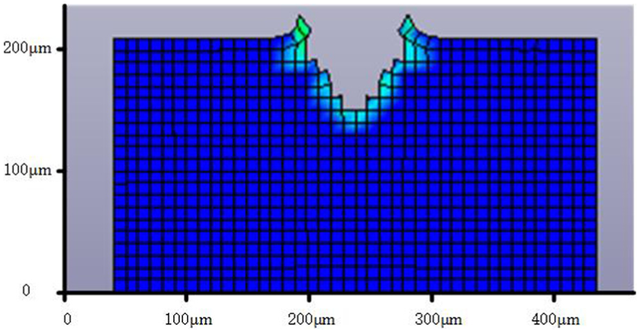
The simulation result is shown in Figure 4, and it is similar to the results in Duan et al. 25 and Fang and Zhang. 26

Workpiece surface for FEM.
It can be seen that during the process, the grit scratches from the shallower to the deeper, and the width of scratch also increases with glass occurring elastic deformation and plastic deformation and fracture removal in turn. JH-2 model can well reflect this changing process of hard–brittle material with both SPH and FEM coupling algorithm. SPH can also well simulate the production of chips because of the existence of material particle. While the heap of chips beside two sides of the scratch makes the scratch seem wider.
During the scratching process of glass, pile-up occurs beside the scratch.27,28 This reflects that glass can also show plasticity under certain conditions. The scratch section in simulation is shown in Figure 5. It can be seen that glass beside the simulated scratch has obvious pile-up which is similar to the pile-up in Fang and Zhang. 26
Simulation scratches section.
Through above analysis, it can be considered that JH-2 material model based on FEM can effectively simulate the elastic–plastic deformation and fracture removal during scratching and cutting process of glass.
Polishing simulation of PCF end surface
JH-2 uses damage parameter D to represent the cumulative damage of brittle material. Damage parameter D is got by calculating the ratio of cumulative plastic strain to fracture plastic strain; it is to say that the damage has already been in areas where plastic strain exists. Research shows that crack of brittle material usually occurs in the area with initial defects and damages which are difficult to be observed. So, plastic strain areas of JH-2 model can be considered as initiation and growth areas of crack.
During the single grit cutting process, the plastic deformation distributions of air hole wall at different times are shown in Figure 6. From Figure 6, it can be seen that air hole wall has gone through elastic–plastic deformation, material removal, crack growth, and edge collapse. These can be divided into three stages in general: edge impact stage (Figure 6(a) and (b)), stable scratching stage (Figure 6(c)), and edge collapse stage (Figure 6(d)–(f)).
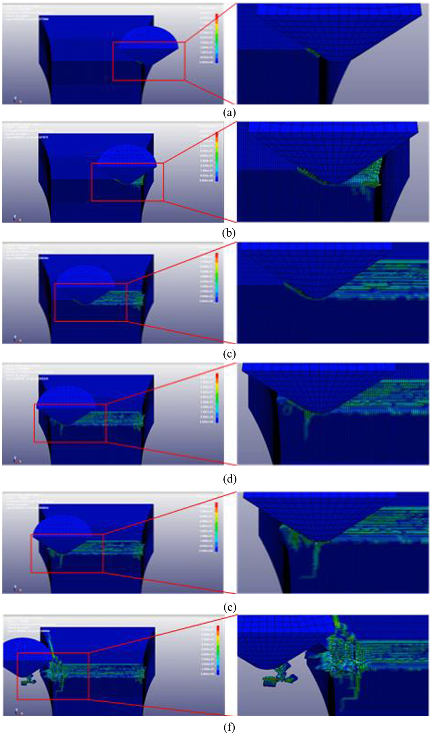
Single grit polishing process: (a) t = 0.0006 µs, (b) t = 0.0020 µs, (c) t = 0.0047 µs, (d) t = 0.0060 µs, (e) t = 0.0062 µs, and (f) t = 0.009 µs.
At the beginning of edge impacting stage, the grit and the edge of air hole wall contact and extrude each other, and glass in the contact area gradually goes through elastic and plastic deformation until it is removed by shear action, as shown in Figure 6(a). When the grit enters fiber hole wall completely, there is a flaw, which is vertical to the direction of the scratch and develops downward, under the scratch and near the edge of hole wall. Meanwhile, glass at the edge of hole wall is lightly protruding outward, as shown in Figure 6(b). When it enters stable scratching stage, glass in the surface of hole wall is mainly removed by shear action which makes a smooth plastic deformation (the green part on the scratch). At the same time, there are traces of tensile fracture in the surface of scratch (the blue intermitting part of scratch). There are nearly no obvious cracks at this stage, as shown in Figure 6(c). As the grit keeps moving to the edge of hole wall, cutting process enters edge collapsing stage. There appears lots of micro cracks located anterior–inferior to grit. Below the grit, there appears a large crack developing downward, and another crack which is normal to the scratch direction and propagates laterally, occurs in the surface of hole wall, as shown in Figure 6(d). Then, micro cracks located anterior–inferior to grit continue to develop, combine, and connect with each other and form edge collapsing. Because the side of hole wall is unconstrained free surface, vertical and lateral defective cracks extend to the side of hole wall while developing toward, as shown in Figure 6(e). Finally, as the grit leaves, part of glass is stripped out from hole wall. There forms a collapse area in the edge of hole wall, and glass around the scratch is protruding outward. At this time, the material is mainly removed in brittle fracture mode, and whole collapse area is strip shape and distribute along the circumferential direction of hole wall, as shown in Figure 6(f).
We can see that the damage of hole wall at the end of scratch is more serious than that at the start of scratch. That is because during the scratching process, the material in anterior–inferior of grit is mainly under compressive stress while the material in lower back of grit is mainly under tensile stress. 29 Besides, tensile stress further increases compared with complete structure because of lack of constraint on the side of hole wall. In model JH-2, under tensile stress, the equivalent stress strength reduces greatly and the material is easier to damage, which is matched with the features that the tensile strength of hard and brittle material is much lower than compressive strength. Thus, the damage of hole wall at the end of scratch is more serious.
Figure 7 shows the maximum principal stress in three surfaces (planes A, B, and C) of the hole wall model when the grit is close to the edge of hole wall. It can be seen that glass next to the grit is under compressive stress and the outer is under tensile stress, and the longer the blue line, the greater the tensile stress. According to the Rankine criterion, crack is initiated when the maximum principal stress exceeds the fracture stress of the materials and propagates normal to this stress direction. So in plane A, cracks may initial nearly normal to the scratch direction and propagate laterally; in plane B, cracks also initial normal to the scratch direction but propagate deeply into the hole wall; and in plane C, cracks lie around the grit. These clearly match with the result in Figure 6.

Orientation of maximum principal stress in three surfaces: (a) the grit is close to the edge, (b) orientation of maximum principal stress in plane A, (c) orientation of maximum principal stress in plane B, and (d) orientation of maximum principal stress in plane C.
Discussion
When the grit leaves the fiber hole wall, the size of cracks and peripheral collapsing area reaches the maximum. In this study, we use the maximum longitudinal crack length and the size of collapse area (the area with both lateral cracks and longitudinal cracks initiation) as quantitative values of damage, as shown in Figure 8.
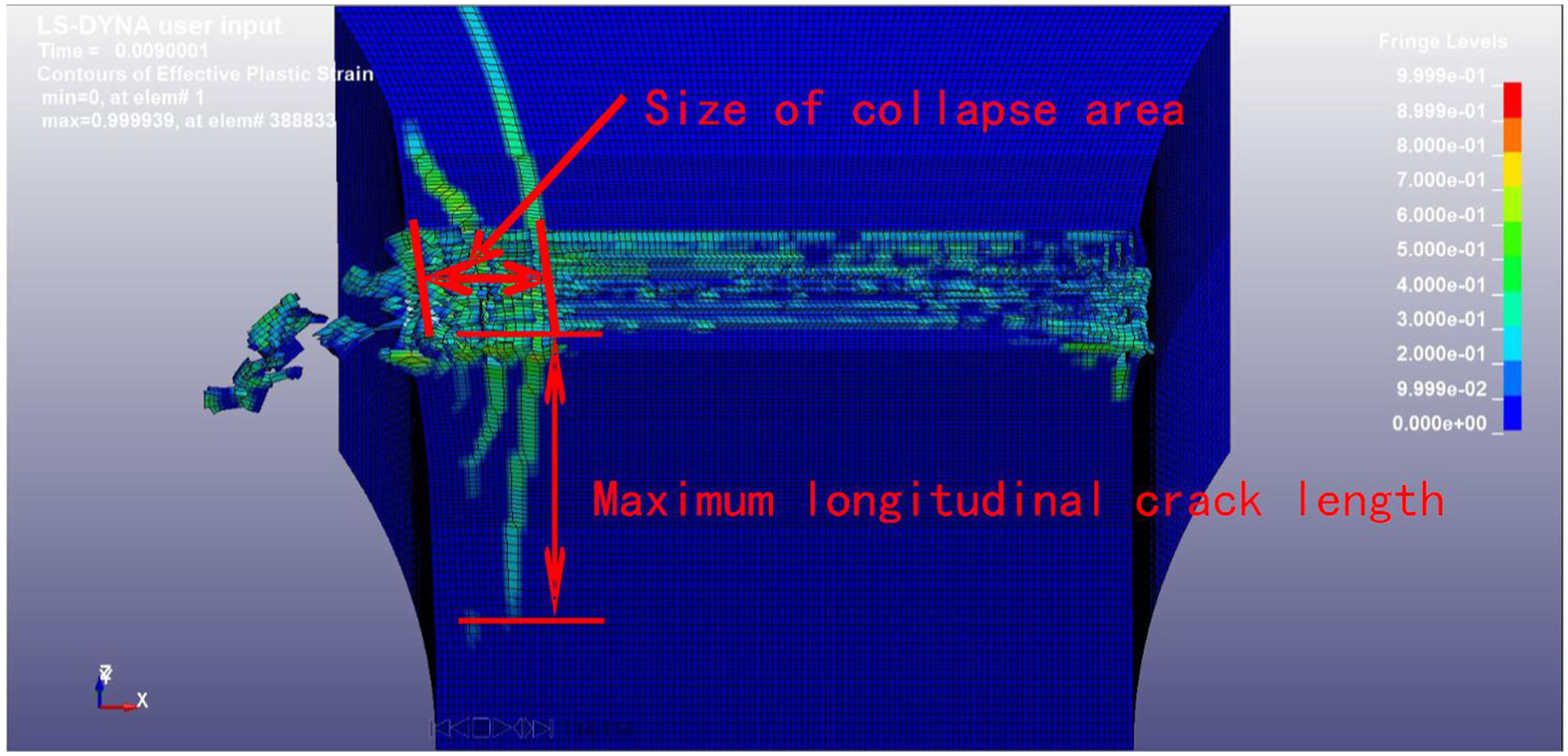
Illustration of size of collapse area and maximum longitudinal crack length.
Analysis of the damage on edge of hole wall
When cutting depths are 20, 50, 80, 100, 120, and150 nm, respectively, and tip radius of grit are 50, 100, 200, and 300 nm, respectively, the changes of collapse area size are shown in Figure 9 and changes of maximum longitudinal crack length are shown in Figure 10. We can figure out that with the cutting depth and tip radius increasing, the size of collapse area increases. And the changes of cutting depth have much influence on the size of collapse area. Because of the randomness of crack initiation, the changes of maximum longitudinal crack length have much more fluctuation compared to collapse areas in Figure 10. When cutting depth is 150 nm, the maximum longitudinal cracks by different tip radii have been reached to the edge of model. At this time, the boundary conditions produce a restriction to the maximum longitudinal cracks, which leads to the four groups with similar crack length. But from the whole tendency, we can find that the maximum longitudinal crack length increases with the increment of cutting depth and tip radius. The changes of cutting depth have much more influence on maximum depth of longitudinal cracks, which is similar to the change law of collapse area size.

Variation of the size of collapse area under different parameter conditions.

Variation of maximum longitudinal crack length under different parameter conditions.
When precisely machining brittle materials, it often uses the critical cutting depth to distinguish the machining mode of brittle regime and that of plastic regime. When cutting depth is lower than the critical depth, brittle materials can also realize the machining process similar to plastic materials to get a very smooth surface. The hole walls of PCF are easier to damage than the complete solid structure without holes during cutting process. Therefore, to realize plastic regime machining without crack damage, PCF needs to assure that there is no damage at the edge of hole walls. Figure 11 shows the plastic strain of hole wall edge after cutting by different tip radii. We can see that scratches away from the edge are smooth without cracks while glass on the edge of hole walls produces a large plastic deformation and protrudes outward. As shown in Figure 11(a) and (b), when tip radii are 50 and 100 nm, the deformation of edges does not lead to obvious cracks. And when tip radii add up to 200 and 300 nm, the positions of deformation start to generate slight cracks as shown in Figure 11(c) and (d) (the red marked region in (c) and (d)), that is to say at this time, the edges of hole walls are in the critical condition of generating crack damage. According to previous analysis, collapse area and cracks are mainly influenced by cutting depth. It should be noted that in this simulation, the smaller size of the fine mesh, the better; but if the mesh size is reduced to 10 nm or less, the computation time will increase exponentially (we use HP Z820 workstation with CPU E5-2643 and RAM 256 GB to do simulation right now). Thus, we can approximately think that the critical cutting depth of this PCF without damage is about 20 nm.

Cutting depth of 20 nm, hole wall edge damage caused by different tip radii: (a) tip radius of 50 nm, (b) tip radius of 100 nm, (c) tip radius of 200 nm, and (d) tip radius of 300 nm.
Cutting force
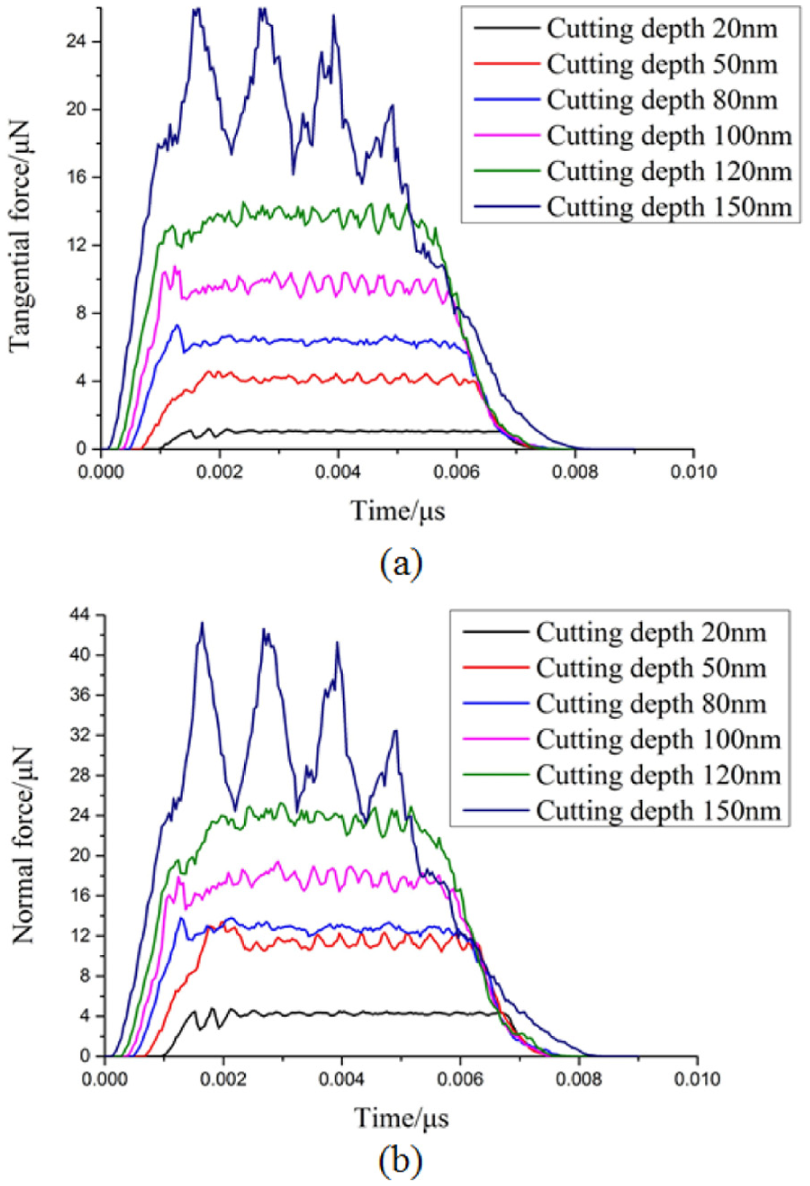
When tip radii are 50 and 300 nm, tangential force and normal force in different cutting depths versus time are shown in Figures 12 and 13, respectively. With different tip radii, the relationship between cutting force and time, and the relationship between cutting force and cutting depths are similar, so only two conditions are shown. We can see that the initial force is zero, and then it increases suddenly, which indicates the grit begins to contact with hole wall. When cutting force increases to a certain value, it gets into a relatively stable status, which indicates the grit has entered the surface of hole wall completely. Subsequently, cutting force begins to decline to zero gradually, which indicates grit scratch out of hole wall surface. During the whole cutting process, tangential forces are all lower than normal forces, and at the same time, both two change laws are similar. Observing the relatively stable status of cutting force, we can find that when cutting depth is 20 nm, cutting force has nearly no fluctuation. With the increment of cutting depth, cutting force begins to fluctuate and the fluctuation range becomes larger and larger. Stable cutting force indicates that the material is removed in plastic regime while the fluctuating cutting force indicates brittle fracture. The more volatile cutting force is, the more serious brittle fracture is. Due to the consistent route of grits with increment of cutting depth, contacting time between grit and hole wall is in advance and the time to leave delays. Ideally, the end of cutting force curve in different cutting depths presents a consistent process with the beginning. However, we can find, in Figures 12 and 13, the tangential force and normal force both reduce ahead, which is because air hole wall end appears the edge collapse. The deeper cutting depth is, the earlier the reduction of cutting force is and the longer the reduction continuing time is, which indicates edge collapse is the more serious.

Tip radius of 50 nm, with different cutting depths, cutting force versus time: (a) tip radius of 50 nm, with different cutting depths, tangential force versus time and (b) tip radius of 50 nm, with different cutting depths, normal force versus time.
Tip radius of 300 nm, with different cutting depths, cutting force versus time: (a) tip radius of 300 nm, with different cutting depths, tangential force versus time and (b) tip radius of 3000 nm, with different cutting depths, normal force versus time.
Averaging cutting force in stable status, we can get the change law of tangential force and normal force under different cutting parameters, as shown in Figure 14. As shown in this figure, tangential force and normal force both increase with the increment of cutting depth and tip radius. Compared to cutting depth, the changes of tip radii have much more influence on cutting force. Larger tangential force and normal force can make more damage on materials during machining process, which corresponds to the change law of size of collapse area and maximum depth of longitudinal cracks. Therefore, it can realize precision machining of PCF in plastic regime by monitoring the changes of cutting force.
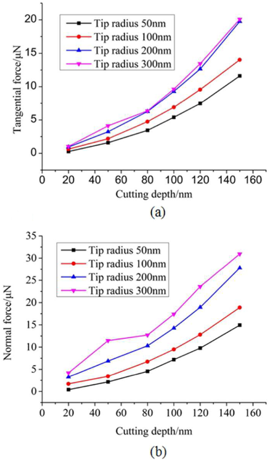
Variation of cutting force under different parameter conditions: (a) variation of tangential force under different parameter conditions and (b) variation of normal force under different parameter conditions.
Conclusion
In order to analyze PCF end face polishing process, this process is simplified as single grit cutting single air hole wall. We use FEM and J-H2 material model to complete the simulation analysis and conclusions are as follows:
J-H2 can simulate material removal of glass during polishing process.
The edge of PCF air hole walls is easily damaged during polishing process and the collapse area distributes along the circumferential direction of an air hole wall.
Both the cutting depth and the tip radium have an influence on the polishing results. When the cutting depth and the tip radium are increased, the cutting force increases accordingly, and the final damage is more severe. Of these two factors, the cutting depth has a greater impact.
This solid polarization-maintaining PCF has a critical cutting depth of about 20 nm. The polishing process with a cutting depth less than 20 nm can have almost no damage on the PCF end face.
Footnotes
Acknowledgements
The authors would like to gratefully acknowledge the instrumental assistance from Song Honghai.
Academic Editor: Michal Kuciej
Declaration of conflicting interests
The author(s) declared no potential conflicts of interest with respect to the research, authorship, and/or publication of this article.
Funding
The author(s) disclosed receipt of the following financial support for the research, authorship, and/or publication of this article: This study was supported by the National Key Scientific Instrument and Equipment Development Projects (2013YQ040877).