
Abstract
Friction stir welding of Ti–6Al–4V alloy sheets was successfully performed with a tungsten carbide (WC) tool, and the effect of the tool rotational speed on the microstructure and mechanical properties of the joints was evaluated. The microstructure was investigated using field emission scanning electron microscopy, electron backscattered diffraction and X-ray diffraction measurements. Tensile, Charpy impact and Vickers hardness tests were performed to evaluate the joints’ mechanical properties. The process peak temperature of each welding condition was measured at the bottom of a specimen. Regardless of the welding conditions, the alpha (α) and alpha prime (α′) phases were detected in the stir zone, whereas the base metal was composed of alpha (α) and beta (β) phases. The tensile strength and hardness of the stir zone increased as the tool rotational speed increased. The impact absorption energy was found to be equal to that of the base metal. Moreover, a phase transformation from the β to the α′ phases occurred in the stir zone during friction stir welding and the evolution of the microstructure in the stir zone significantly affected the mechanical properties of the joints.
Introduction
Ti–6Al–4V alloys are one of the most widely used titanium alloys due to their superior toughness, corrosion resistance and specific strength. Ti alloys are commonly used in the aerospace and defence industries. Moreover, they have recently been used in the sporting goods industry. Various fusion welding methods are currently used to weld Ti and Ti alloys including laser beam welding, gas metal arc welding) and gas tungsten arc welding. Fusion welding methods, however, generate significant distortion and a coarse microstructure at the fusion zone. One potential solution to this problem could be the solid-state joining technique.
Friction stir welding (FSW), developed by the Welding Institute, is considered to be a reasonable method. FSW has mostly been applied as a solid-state welding technique to lightweight and low-melting-point materials such as Al1,2 and Mg.3,4 However, recently, FSW has been tested on materials that are strong and have a high melting point.5–9 Some studies on FSW have also investigated the microstructure and mechanical properties of pure Ti and Ti alloys;5,10–15 however, there is still a considerable gap in knowledge about this topic. The Ti–6Al–4V alloy is extremely hard and undergoes allotropic transformation; it also exhibits considerable microstructural evolution during FSW. As a result, it is difficult to study how FSW affects Ti–6Al–4V alloy sheets, and consequently, there have been few studies on the relationship between the microstructures and mechanical properties of the FSW joints within the Ti–6Al–4V alloy sheets.
Herein, Ti–6Al–4V alloy sheets were friction-stir-welded at different rotational speeds with a fixed feed rate. The main aim of this study is to investigate the effect of the tool rotational speed on the microstructural evolution and mechanical properties of the alloy. The relationship between the microstructure formation and mechanical properties of the FSW joints is also discussed. A texture study was conducted using electron backscattered diffraction (EBSD) measurements to obtain a better understanding of the phase transformation in the stir zone.
Experimental procedures
Ti–6Al–4V alloy sheets (100-mm wide, 2-mm thick and 300-mm long) were used as the base metal; their chemical composition is listed in Table 1. The procedure produced tungsten carbide–based tools with a 1.8-mm probe length, 15-mm shoulder diameter and 6-mm probe diameter. To prevent oxidation in the stir zone, an argon shielding gas was used in the working area. A thermocouple was placed underneath the base metal to measure the temperature of the stir zone. The tool rotational speeds varied between 300 and 500 r/min, and the tool travel speed was maintained at 200 mm/min.
Chemical composition of Ti–6Al–4V alloy (wt%).

The microstructure in the stir zone was observed using optical microscopy (OM), field emission scanning electron microscopy (FE-SEM) and EBSD. X-ray diffraction (XRD) measurements were used to investigate the phase transformation in the stir zone and were performed using CuKα radiation. The welding zone was cut perpendicularly to the welding direction (WD). The transverse cross section of the stir zone was mechanically polished using a diamond paste, and the specimens were etched with a solution that consisted of 50 mL H2O, 40 mL nitric acid and 10 mL HF and observed by an optical microscope (GX 51). The SEM (JEOL, JSM-7100F) and EBSD samples were etched at −40°C with a solution consisting of 5 mL HClO4, 35 mL C4H9OH and 60 mL CH3OH at a voltage of 45 V, and the etching was observed using the HKL channel 5 software. Figure 1(a) and (b) shows a schematic illustration of the tensile test and the Charpy impact test specimen preparation, respectively. To precisely evaluate the mechanical properties of stir zone at various process condition, the tensile test specimens (JIS 2201 sub-size) were cut parallel to the WD in the stir zone and evaluated at room temperature by an Instron-type tester (INSTRON 8801) with a crosshead speed of 1 mm/min. Vickers hardness (Mitutoyo, HM-112) was measured along the transverse stir zone centreline using a 9.8-N load for 10 s. As shown in Figure 1(b), the Charpy impact tests were performed with KS B 0809 specimens (thickness: 2 mm) using a Charpy impact tester (Zwick/Roell, RKP-450) with a hammer degree of 150°.
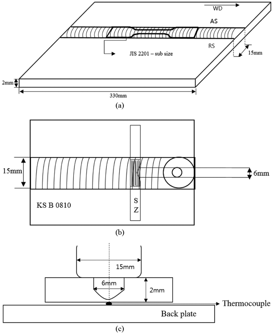
Schematic illustration of FSWed Ti–6Al–4V alloy sheets for (a) tensile test specimen and (b) Charpy impact test specimen.
Results and discussion
Effect of tool rotational speed on microstructure
Figure 2 shows a low-magnification overview of a cross section of the FSW joints. The Ti–6Al–4V alloy sheets were successfully friction-stir-welded at various tool rotational speeds at a fixed tool travel speed, and no defects were obtained in the cross-sectional images. The stir zone appeared to be shaped like a basin; the advancing side and retreating side are shown in Figure 2. Narrow heat-affected zones were also found between the stir zone and base metal.

Cross section OM image perpendicular to WD.
Figure 3(a) shows a schematic diagram of the equilibrium phase diagram of the Ti–6Al–4V alloy, 16 and Figure 3(b) shows the peak process temperatures measured at the bottom of the stir zone. The beta (β)-transus temperature was approximately 980°C in this alloy. The process peak temperature was measured at 870°C, 907°C, 938°C and 949°C for rotational speeds of 350–500 r/min. The temperature gradually increased as the tool rotational speed increased. However, all the measured process peak temperatures were somewhat lower than the β-transus temperature.

(a) Schematic diagram with Ti–6Al–4V alloy and (b) peak temperatures at different rotational speeds.
The FE-SEM image of the base metal (Figure 4(a)) shows that the microstructure comprised primary alpha (α) phases with a dark contrast that transformed into beta (β) phases with a bright contrast. This is considered to be the deformed laminated structure; however, it is difficult to accurately determine the grain size because the β phases were unclear. Figure 4(b)–(d) shows the microstructure in the stir zone at various tool rotational speeds: 400, 450 and 500 r/min. These microstructures were quite different from those of the base metal. The stir zone consisted α phases and martensitic alpha prime (α′) phases that had a needle-like shape. The volume fraction of α′ increased as the tool rotational speed increased; these results suggest that the phase transformation from β into α′ phases may have occurred despite the fact that the process peak temperature did not reach the β-transus temperature. The initial martensitic transformation temperature (Ms, Figure 3(a)) is believed to have decreased from the original β-transus temperature because of super-cooling that occurred just after the peak temperature was reached. This phenomenon is believed to often occur during the welding and joining processes. As the tool rotational speed increased from 300 rpm to 500 rpm, the process peak temperature increased in the stir zone. It resulted in increase of the cooling rate. And to conclude, the formation of alpha prime (α′) phase strongly depends on the cooling rate and the amount of alpha prime (α′) phase increases with increasing process peak temperature.
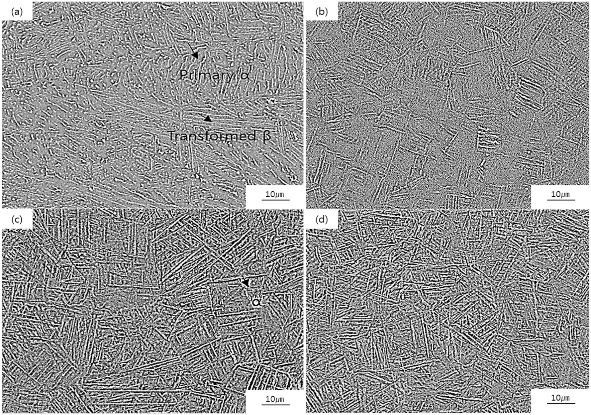
SEM images of base metal and stir zone samples at different RPM values: (a) base metal, (b) 400 r/min, (c) 450 r/min and (d) 500 r/min.
Figure 5 shows the XRD patterns of the base metal and stir zone at various tool rotational speeds. The diffraction peak of the base metal is composed of α and transformed β phases. The β peak was not detected in the stir zone because the β phase was transformed into the α′ phase during FSW. The α and α′ phases have the same crystal structure (hcp); therefore, they were both found to be at the same position. However, few of residual beta (β) phases could be retained in the stir zone, if the beta (β) phases didn’t fully transform into the alpha prime (α′) phase during friction stir welding.
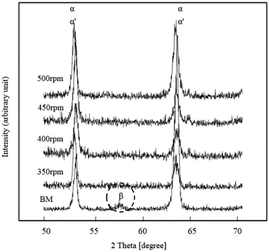
XRD patterns of FSWed Ti–6Al–4V sheets.
Figure 6 shows the EBSD inverse pole figure (IPF) maps of the ND-plane of the base metal (Figure 6(a)) and the stir zone (Figure 6(b) and (c)). Both alpha (α) phases of nonuniform and flat type and alpha prime (α′) phases with characteristic morphology of needle shape were observed in the stir zone. The stir zone of the joint fabricated by the low tool rotational speed showed relatively small α′ phases (Figure 6(b)); however, the stir zone of the joint manufactured by the high tool rotational speed showed much larger α′ phases (Figure 6(c)). This is believed to be because the process peak temperature increased as the tool rotational speed increased.

EBSD IPF maps for (a) base metal, (b) 350 r/min and (c) 500 r/min.
Effect of the tool rotational speed on the mechanical properties
Previously, while investigating the effect of process conditions on the tensile strength of FSW joints within Ti–6Al–4V alloy sheets, Zhou et al. 15 reported that the tensile strength decreased as the tool rotational speed increased. However, Kitamura et al. 10 reported the opposite. These two types of trends can be confirmed from Figure 7, which shows the stress–strain curves of the base metal and the joints fabricated at various tool rotational speeds. When the tool rotational speeds were below 450 r/min, the tensile strength increased as the tool rotational speed increased. However, the opposite occurred when the tool rotational speed was over 450 r/min. These trends were also confirmed on elongation. This suggests that the tensile properties are seriously affected by α′ phase volume fraction which depends on the tool rotational speed; the speed also seems to affect the process peak temperature as it strongly influenced both the formation of the α′ phase and the amount of the phase that transformed during the FSW.

Stress–strain curves of base metal and stir zone specimen at different RPMs.
Figure 8 shows the Vickers hardness distribution on the central cross-sectional area of the stir zone. The hardness values of the stir zone are shown to be higher than those of the base metal, which is shown to have increased as the tool rotational speed increased. This is believed to be due to the large amounts of the α′ phase formed in the stir zone at high tool rotational speeds, as shown in Figures 4 and 6.

Vickers hardness profiles of stir zone specimens at different RPMs.
Figure 9 shows the amount of energy absorbed during the Charpy impact test that was used to evaluate toughness. When the tool rotational speed reached 400 r/min, the impact absorption energy was 5.2 J; this is equal to the grade of the base metal. However, the absorption energy increased slightly when the tool rotational speed was 450 r/min; this is believed to be because the joints have good toughness in the stir zone due to a remarkably fine microstructure formed by recrystallization during the FSW. After the peak value was observed at 450 r/min, however, the toughness was found to decrease. The excessive formation of the α′ phase at high tool rotational speeds, as shown in Figure 6(c), is believed to be the cause of this.
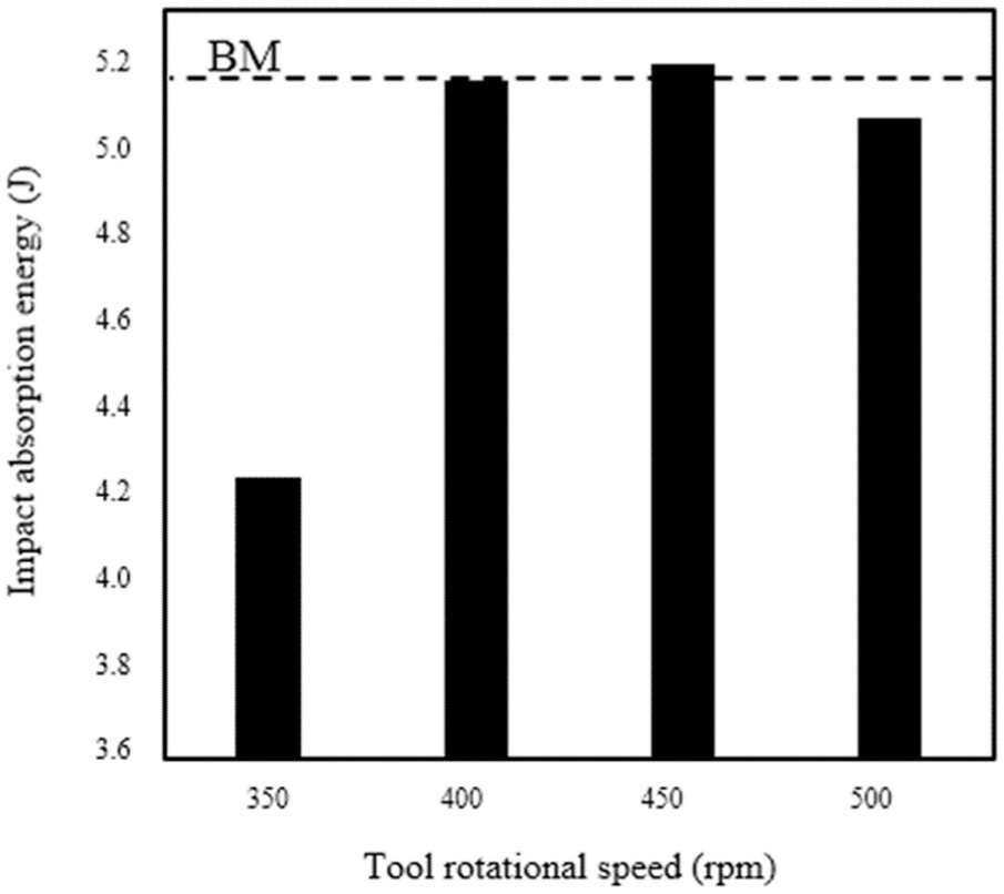
Impact absorption energy of base metal and stir zone specimens.
Correlation among the process peak temperature, the phase transformation and the mechanical properties
Figure 10(a) and (b) shows an FE-SEM image and EBSD IPF map in the stir zone of the joint that was fabricated with a tool rotational speed of 300 r/min, wherein an interesting microstructure can be observed. α and α′ phases can be identified in the centre region, as shown in Figure 6(b) and (c). However, the microstructure comprises α and β phases in the same manner as that of the base metal (shown in Figure 6(a)) at the bottom of the stir zone. These results imply that the phase transformation from β into α′ occurred in the centre region but did not occur at the bottom; in other words, the process peak temperature reached that of the Ms temperature in the centre region but not at the bottom (which was close to the probe tip). The process peak temperature was measured to be 840°C, as shown in Figure 11; this suggests that the critical temperature for the phase transformation from β into α′ phases is slightly higher than 840°C. This means that engineers who wish to fabricate joints with high tensile strength should use a process peak temperature that is greater than 840°C along with the appropriate tool rotational and travel speeds; moreover, engineers who want to obtain joints that have good ductility should look to have a process peak temperature that is below 840°C. As a result, the discussion on the results of the tensile test, microstructure observation and process peak temperature reveals the relationship among the tool rotational speed, process peak temperature, phase transformation and mechanical properties of the FSW joints.

FE-SEM image and EBSD IPF map in the stir zone of the joint at 300 r/min: (a)FE-SEM image of stir zone and (b) EBSD IPF map in Enlarged view of square.
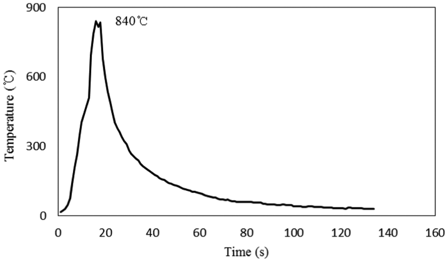
Process peak temperature at 300 r/min.
Conclusion
Ti–6Al–4V alloy sheets were successfully friction-stir-welded without defects at a fixed tool travel speed of 200 mm/min and different rotational speeds between 350 and 500 r/min. The effect of the tool rotational speed on the mechanical properties and microstructure of the FSW joints was thoroughly examined, and the following conclusions have been drawn:
The tool rotational speed affects the process peak temperature, that is, as the speed increases, so does the temperature. It ranges from 870°C to 949°C for speeds between 350 and 500 r/min. The temperature should be under the β-transus temperature in order for the joints to be manufactured with acceptable tensile strength and toughness.
The microstructure of the stir zone comprises primary alpha (α) and alpha prime (α′) phases transformed from beta (β) phases during FSW; the microstructure of the base metal is composed of α and β phases. The process peak temperature reaches the martensitic transformation initiation temperature regardless of the tool rotational speed.
The hardness in the stir zone is higher than that of the base metal, and it increases as the tool rotational speed increases. Tensile strength and toughness also increase with the tool rotational speed up to 450 r/min. Above this speed, however, they decrease. Because the transformed α′ phases form redundantly, they grow due to an excessively high process temperature.
To obtain joints that have acceptable mechanical properties, the tool rotational speed should be optimized, and the phase transformation from β into α′ phases should be controlled during FSW.
Footnotes
Academic Editor: Shan-Tung Tu
Declaration of conflicting interests
The author(s) declared no potential conflicts of interest with respect to the research, authorship, and/or publication of this article.
Funding
The author(s) disclosed receipt of the following financial support for the research, authorship, and/or publication of this article: This study has been conducted with the support of the Korea Institute of Industrial Technology as ‘Research equipment coordination project (kitech JB-17-0007)’.