
Abstract
Because of the problem of a high fuel temperature rise at shut-off, a conventional centrifugal pump could not be used as an aero-engine fuel pump for the afterburner fuel supply. In this study, a centrifugal pump with a cooling bypass was designed to address this problem. Experiments and numerical simulations were conducted to assess the design. The results showed that the circulation cooling achieved by a small amount of cooling fuel from a cooling bypass could effectively solve the problem. When the pump with a cooling bypass operated at shut-off, a large vapour core appeared at the centre of the impeller due to cavitation. This large vapour core reduced both the pump power consumption and the heat generated by friction, thereby greatly reducing the fuel temperature rise in the pump. Further research works showed that the radius of the vapour core was a function of the flow rate and the pump rotational speed. Moreover, the cooling fuel flow rate was regulated by the size of the nozzle hole. It is clear that a centrifugal pump with a cooling bypass overcomes the problem of the high fuel temperature rise in the pump at shut-off.
Introduction
Compared with gear pumps or piston pumps, which are often used as aero-engine fuel pumps for main engine or afterburner fuel supplies, centrifugal pumps offer the attractive advantages of large flow rates, simple structures, light weight and low cost. 1 However, because of the problem of the high fuel temperature rise at shut-off, a conventional centrifugal pump cannot be used as an aero-engine fuel pump for the afterburner fuel supply (called an afterburner fuel pump). The shut-off condition is characterised by the following features:
The pump outlet valve is closed.
The pump is full of fuel.
The pump flow rate is zero (no fuel delivery).
The pump impeller is still in rotation at a high rotational speed.
A conventional centrifugal pump operates at shut-off only at the moment of start-up to minimise the starting load on the driver. However, an afterburner fuel pump in an aero-engine has to operate at shut-off for a long time. However, the pump is usually driven directly by the main engine, without the clutch, for the purposes of weight reduction and mechanical simplicity. Hence, the pump shaft rotates all the time with the main engine, regardless of whether or not fuel is supplied for the afterburner. However, the afterburner is usually turned on (fuel supply) for a short time only in the case of an emergency to augment extra engine thrust. In comparison, the afterburner is turned off (interrupting fuel supply) for a long time under normal flight conditions to save fuel. If a conventional centrifugal pump operates at shut-off for a long time, friction both between components and between the impeller and the fuel will cause the fuel trapped in the impeller chamber to generate a considerable increase in temperature, which is very dangerous for an aero-engine. 2 To ensure the operating safety of an aero-engine, its design requirements typically stipulate that the pump inlet fuel temperature remains below 60°C and that the fuel temperature rise in the pump remains below 40°C. 3
For the purpose of energy saving, the conventional fuel centrifugal pump usually runs near the rated operating condition. During the all course of the flight, the fuel temperature rise in the centrifugal pump for the aircraft fuel system is below 14°C. 4 With the decrease in the flow rate (far from the rated operating point), the fuel temperature rise increases greatly. 5 Therefore, the minimum continuous operating flow is limited. 6 For the conventional fuel centrifugal pump, the operating time at shut-off is so short that the temperature rise in the pump is small and can be neglected, so the problem of the temperature rise in a conventional centrifugal pump at shut-off has rarely been studied. To date, studies on the shut-off condition for a centrifugal pump have mainly focused on the shut-off head7–10 and the shut-off power. 11
However, in the case of the afterburner fuel centrifugal pump, the problem of the high fuel temperature rise at shut-off cannot be ignored. Dowty Fuel Systems Limited 12 designed a centrifugal pump with an inlet throttle valve at the impeller eye to overcome the problem. The flow rate was regulated by the opening degree of the inlet throttle valve, the function of which was to generate a core of fuel vapour at the impeller eye. However, the control on the opening degree of the inlet throttle valve was very complex. Therefore, both the pump weight and the structural complexity greatly increased.
In this study, a centrifugal pump with a cooling bypass was designed to solve the problem of the high fuel temperature rise at shut-off. Experiments and numerical simulations were conducted to assess the design.
Structure design
Original pump
A single-stage, single-suction centrifugal pump was adopted herein as the aero-engine fuel centrifugal pump. This pump was similar to the high-speed partial-emission pump designed by Barske
13
during the Second World War for the rocket fuel supply. Figure 1 shows the structure of the pump (the specific speed

Structure of original pump: (a) whole structure and (b) structure of impeller, volute and diffuser.
Design parameters of impeller blades.

Cooling bypass
To address the problem of the high fuel temperature rise in the pump at shut-off, a tentative idea for circulation cooling by a small amount of fuel from a cooling bypass was considered. A structural improvement to the original pump was then made to facilitate this. Figure 2(a) shows the structure of the cooling bypass. The cooling bypass was composed of two branch pipes, a fuel filter, two nozzles (equal diameter) and a conical return pipe. The branch pipes and the nozzles connected the pump inlet and the impeller chamber. The fuel filter was located between branch pipe-1 and branch pipe-2 to prevent the nozzles from the clogging caused by the fuel impurity. The return pipe was located on the side wall of the diffuser. Figure 2(b) displays the position of the nozzle holes at the bottom plate of the impeller chamber. Figure 2(c) presents the original pump with the cooling bypass (hereinafter referred to as an improved pump). Table 2 lists the design parameters of the cooling bypass. The structural design of the cooling bypass is clearly very simple, showing that it does not add significant extra weight to the pump.

Structure of improved pump: (a) cooling bypass, (b) position of nozzle holes and (c) pump with cooling bypass.
Cooling bypass design parameters.

Figure 3(a) shows that, in the improved pump at shut-off, a small amount of fuel (called cooling fuel) from the pump inlet enters the branch pipe, flows through the shaft sleeve, sprays from the nozzles into the impeller chamber and returns through the return pipe to the fuel tank. The heat generated by friction in the pump was carried away by the cooling fuel. The cooling fuel flowing through the shaft sleeve also played an important role in lubricating and cooling the high-speed rotating shaft.

Fuel flow direction: (a) improved pump at shut-off and (b) original pump at a low flow rate.
Although the cooling fuel also entered the impeller chamber from the cooling bypass, the operating state of the improved pump at shut-off (the inlet and outlet valves being closed) was very different from that of the original pump at a low flow rate (the inlet and outlet valves being open). The flow rate of a centrifugal pump was usually adjusted by the outlet valve, which allowed a small amount of fuel (also called the cooling fuel) to enter the impeller chamber of the original pump from the pump inlet and return from the outlet of the diffuser to the fuel tank (Figure 3(b)). In other words, when the afterburner was turned off, a small amount of cooling fuel was allowed to directly enter the impeller chamber of the original pump from the pump inlet to carry away the heat generated by friction in the pump. This seemed to be a sound solution to the problem of the high fuel temperature rise in the pump at shut-off. However, the study results showed that this was not a feasible solution. A detailed analysis would be provided later.
Experimental assessment
Experimental equipment
An aero-engine fuel centrifugal pump test rig (Figures 4 and 5) was set up to experimentally measure the fuel temperature rise in the pumps. The test rig was a closed circulation system using China No. 3 jet fuel (RP-3). A booster pump was used to pressurise the fuel and deliver it from the fuel tank to the test pump. A heat exchanger was connected in series to the pipeline system to decrease the fuel temperature rise in the pipeline system. The pump rotational speed, achieved using a two-stage speed-increasing gear box driven by an electric motor, was measured by a tachometer JFXM/AHMVO with the uncertainty of ±15 r/min. The flow rate, regulated by the flow control valve JFXAM-100C, was measured by a flow meter JFXGY-15 with the uncertainty of ±0.05 m3/h. The pump shaft power was measured by a power meter JFXRH-3P51 with the uncertainty of ±10 W. The fuel inlet and outlet temperatures were measured by temperature sensors JFX/P-20 with the uncertainty of ±0.1°C. The fuel inlet and outlet pressures were measured by pressure gauges Y-100 with the uncertainty of ±0.01 MPa.

Schematic diagram of aero-engine fuel centrifugal pump test rig.

Real picture of aero-engine fuel centrifugal pump test rig: (a) test pump (without measuring instruments) and (b) test bed.
Experimental results
Three groups of comparative tests were conducted using the test rig at different non-dimensional flow rates (

Fuel temperature rise versus non-dimensional flow rate (by experiment).
The fuel temperature rise in the original pump at low flow rates obviously exceeded the maximum permissible temperature rise (40°C). Although the fuel temperature rise in the original pump might fall below 40°C as the flow rate increased by expanding the outlet valve opening, this delivered more heat to the fuel tank (as a heat sink). The fuel temperature rise in the improved pump at shut-off was below the maximum permissible temperature rise and, at any given flow rate, was much lower than that in the original pump. In addition, the improved pump delivered less heat to the fuel tank than the original pump at the same flow rate. It is clear that the circulation cooling by a small amount of cooling fuel from the cooling bypass solves the problem of the high fuel temperature rise in the pump at shut-off.
Numerical simulations
Mesh and independence verification
The meshes of the computational domains (Figure 7) of both the original and improved pumps were generated using ICEM CFD 14.0 software. Given the structural complexity of the pumps, unstructured multi-block tetrahedral meshes with prism grids near the walls were used. The computational domain of the original pump (Figure 7(a)) was divided into three parts: the inlet, impeller and volute domains. The impeller domain was a dynamic rotation domain with an anticlockwise direction. The inlet and volute domains were static domains. Dynamic–static interfaces (Figure 7(b)) were established between the dynamic and static domains. The computational domain of the improved pump (Figure 7(c)) included the inlet, impeller and volute domains. It also included a branch domain and a return domain.

Mesh of computational domains: (a) original pump, (b) interfaces between domains and (c) improved pump.
A non-dimensional height ‘Y plus’ was examined to limit the model error of the turbulence model near the wall boundary layer and to ensure that the Y plus of the first layer mesh near the wall was between 5 and 20. Four mesh schemes from sparse to dense (Table 3) were employed to test the mesh independence by solving the pump outlet pressure under the design operation condition.
Mesh elements in different computational domains.

The comparison of the pump outlet pressure between the simulation and experimental results (Figure 8) indicated that the simulation error caused by the mesh gradually decreased with an increase in the number of mesh elements. The No. 4 mesh was adopted herein considering the limitation of computing ability.
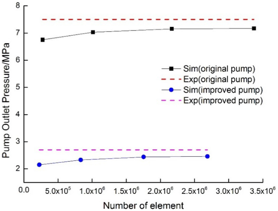
Pump outlet pressure versus mesh element number.
Simulation process
The fuel temperature rise in the pump was related to the flow field. Considering the cavitation effects,14,15 the real flow pattern in the pump was a vapour–liquid two-phase flow, which could be described by the fluid mechanics governing equations (i.e. continuity, momentum and energy equations). A shear stress transport (SST) turbulence model 16 was introduced to close the above equations dealt by the Reynolds average. Moreover, a cavitation model based on the Rayleigh–Plesset equation17,18 was utilised to describe the cavitation process. The transient numerical simulations were conducted using ANSYS CFX 14.0 software. The simulation parameters and boundary conditions were as follows:
At the inlet: Total pressure, liquid volume fraction (
At the outlet: Mass flow rate, liquid volume fraction (
At the interfaces: The frame change was set to be transient rotor–stator, and the mesh connection was set to be a general grid interface (GGI).
Solver control: The time step (
Cavitation setup: The Zwart–Gerber–Belamri cavitation model
19
was adopted. The bubble radius (
Simulation results
The numerical simulations were conducted under the same operation conditions as the experiments. Figure 9 shows that the fuel temperature rise curve from the simulation results is similar to that from the experimental results (Figure 6). However, the simulation values were lower than the experimental values at the same flow rates. It was because that the heat generated by the friction between the impeller shaft and the bushing had not been considered in the simulations, but the heat was transferred to the fuel.

Fuel temperature rise versus non-dimensional flow rate (by simulation).
Results and discussion
Analysis of the cooling principle
Explaining the big difference in the fuel temperature rises of the original and improved pumps at the same flow rates (Figure 6), which might be related to the flow fields in the pumps, was not easy. Flow visualisation
21
was known to be a good method of analysing the flow fields, but applying visualisation instruments to a high-pressure, high-speed, small-volume pump was very difficult. Therefore, numerical simulation analyses were adopted herein. Taking the operation condition
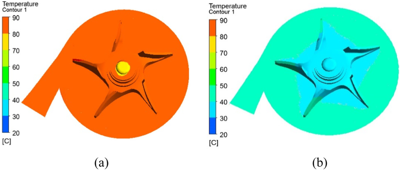
Temperature contour of pump chamber cross section: (a) original pump and (b) improved pump.
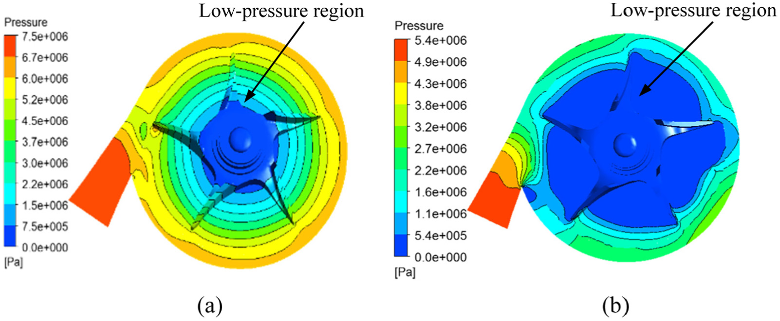
Static pressure distribution contour of pump chamber cross section: (a) original pump and (b) improved pump.

Vapour volume fraction contour of pump chamber: (a) original pump and (b) improved pump.
Figure 10(a) shows that the fuel temperature in the original pump chamber is approximately 88°C, while Figure 10(b) displays that the fuel temperature in the original pump chamber is approximately 41°C. Figure 11(a) shows a small low-pressure region at the inlet of the impeller in the original pump, while Figure 11(b) presents a large low-pressure region at the centre of the impeller in the improved pump. Figure 12(a) shows no vapour-phase region in the pump chamber of the original pump, whereas Figure 12(b) illustrates a large vapour-phase region (referred to hereinafter as a vapour core 22 ) at the centre of the impeller in the improved pump. It is clear that there are great differences in the flow fields of the original and improved pumps at the same flow rate.
Due to the existence of the large vapour core at the centre of the impeller (i.e. the impeller chamber was nearly empty), the pump shaft power (


where
For calculation simplicity, all

where q is the heat rate and

The calculation results showed that, at
Analysis of vapour core
The fuel at the impeller inlet was pushed towards the volute because of the centrifugal force, thereby forming a low-pressure region (Figure 11). When the pressure in the low-pressure region decreased to

Definition of vapour core radius.
The vapour core was formed due to cavitation. With respect to cavitation, we naturally thought of cavitation erosion.
24
Cavitation erosion occurred when vapour bubbles, which were formed at a low pressure, subsequently imploded at a high pressure. If the implosions occurred near the surface of the impeller, they would cause damage to the impeller.
25
For the conventional centrifugal pump, the cavitation erosion usually occurred at the leading edge of the impeller blades.
26
However, for the improved pump at shut-off, this was not of concern. Figure 14 shows the change in the vapour core with the impeller rotation, where

Change of vapour core with impeller rotation: (a)
Centrifugal pumps generally have three kinds of blades (i.e. backward-curved, radial and forward-curved). Figure 15 shows the velocity triangles at the impeller inlet and outlet for a backward-curved blade, a straight radial blade and a straight radial blade with a vapour core. In Figure 15,
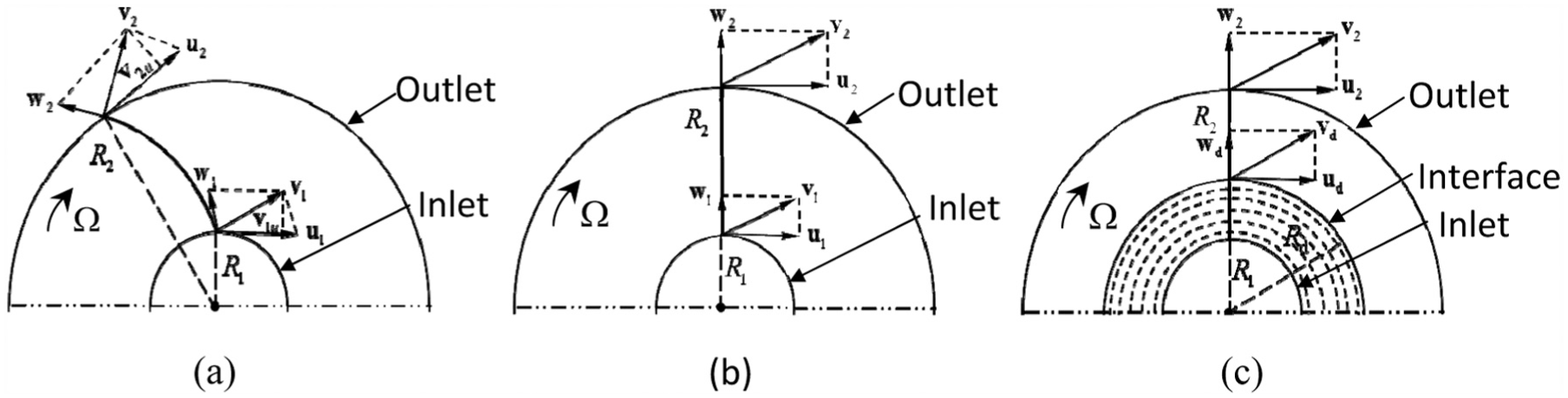
Velocity triangles at impeller inlet and outlet: (a) backward-curved blade, (b) straight radial blade and (c) straight radial blade with vapour core.
Assuming an infinite number of blades, ideal fluid behaviour and neglecting all types of losses, the theoretical head equation 27 for a centrifugal pump with backward-curved blades is calculated by

where
The operating point of the pump was related to the pipeline system characteristics. The pipeline system energy head (

where K is the load coefficient. Accordingly,

where
Control on the cooling fuel flow rate
The pump rotational speed at shut-off was considered nearly constant. Hence, according to equation (7),

where C is the discharge coefficient,

where A is the nozzle hole cross-sectional area (
According to the literature 30

for
As equation (8) shows,
The nozzle exit position must be considered. Figure 16 illustrates the position and the state of the nozzle exit at the three different flow rates. A nozzle exit located outside the vapour core might lead to

Vapour volume fraction contour of pump chamber in axial plane: (a)
Conclusion
In this study, a centrifugal pump with a cooling bypass was designed to act as an aero-engine fuel centrifugal pump for the afterburner fuel supply. The study focused on how to solve the problem of the high fuel temperature rise in the pump at shut-off. The main conclusions drawn from the research results were as follows:
When the pump with a cooling bypass operates at shut-off, a small amount of cooling fuel from the cooling bypass entered the impeller chamber and carried away the heat generated by friction in the pump. The circulation cooling by a small amount of cooling fuel from the cooling bypass solved the problem of the high fuel temperature rise in the pump at shut-off.
At shut-off, a large vapour core appeared at the centre of the impeller due to cavitation. This reduced both the pump power consumption and the heat generated by friction, thereby greatly reducing the fuel temperature rise in the pump.
A formula for the vapour core radius was derived. The vapour core radius was a function of the flow rate and the pump rotational speed. The vapour core stably existed in the pump at shut-off.
The cooling fuel flow rate was regulated by the size of the nozzle hole. For normal circulation of the cooling fuel, the nozzle exit should be located in the vapour core.
The problem of the high fuel temperature rise in the centrifugal pump at shut-off is solved, making it possible for a centrifugal pump to be used as the afterburner fuel pump in aero-engines. Considering the many advantages of the centrifugal pump, a centrifugal pump used as the main engine fuel pump or both as the main engine and the afterburner fuel pump are worthy of future research.
Footnotes
Appendix 1
Acknowledgements
The author(s) thank Mr Gong for the experimental help and Editage for the English language editing.
Academic Editor: Jose Ramon Serrano
Declaration of conflicting interests
The author(s) declared no potential conflicts of interest with respect to the research, authorship, and/or publication of this article.
Funding
The author(s) disclosed receipt of the following financial support for the research, authorship, and/or publication of this article: This work was funded by the National Advanced Aero Engine Technology Research Program.