
Abstract
This work presents results from the project EvTec, which focus on the design, construction, and testing of an electric vehicle with special features such as modular design, multimotor, power source, digital control, autonomy, and connectivity. The proposed architecture explores the use of the Android-based Control Ecosystem, which integrates the Operating System Android, as part of the open-source control of the vehicle. The objective of this work is to design a platform that enables connectivity with the cloud for monitoring and remote controlling purposes. Results are reported about the feasibility of sending and storing information and in general interacting with a remote server. Vehicle control signals and sensor data were shared remotely at a rate of 200 ms per cycle. The data sent for storage in the cloud reconstructed very well the signals, with no data loss, proving its potential for monitoring purposes. This work also presents a brief discussion about the weakness and strengths of the concept, and the future work toward the potential impact and integration with autonomous driving.
Introduction
New cars are equipped with a fixed set of software and hardware, which in most of cases cannot be upgraded once vehicles leave the factory floor. Nowadays, the way in which people interact with cars is shifting toward a more customizable experience, much more similar to what a smartphone can offer. 1 Update/upgradeability and ease for customization are features that need to be considered in vehicles and in many commercial products, for example, in home appliances. Every automotive designer is aware of these issues, and efforts have been made to implement OSs of mobile device for infotainment and navigation. 2 At the same time, recent studies suggest that mobile device OSs, and in particular the open source, universally available Android OS platform, can be used for more critical functions. For example, the use of sensors for safe drive, 3 the interfacing for the powertrain control,4,5 and the use of apps to tune suspension, brakes, and/or steering systems 1 are all examples of feasible uses of the mobile device characteristics in the vehicle domain. A tablet or smartphone can be used as a modular interface, 6 to take advantage of their connectivity capabilities to help in the vehicle control, customization, upgradability, and the everyday new features that computational systems have.
The next frontier in transportation for humans is autonomous mobility. The Google Car is set to hit the road by 2020 7 aided by sophisticated software, hardware, and the Internet. Connectivity, customization, and autonomous driving seem to have an important place in the future automobile market.
This research project analyzes the performance of a platform that connects an electric vehicle with a remote server using a mobile device, which in turn is in close communication with the vehicle controller. Performance information such as the sending/receiving frequency, data losses, communication delays, and reliability of the system is analyzed for a first level (Level-1) vehicle connectivity: vehicle monitoring. Testing was implemented in the powertrain and steering systems of the EvTec prototype, a modular electric vehicle. The ultimate goal of the EvTec project is to provide a test bench for an original approach toward the paradigm of connectivity and autonomous driving. Two more levels of connectivity are defined and discussed: (Level-2) vehicle monitoring with sending/receiving warnings and (Level-3) vehicle monitoring with remote control.
This article is organized as follows. Section “Modular architecture” presents the modular architecture of the vehicle. Section “Control system” describes the elements of the control system such as sensors, actuators, communication system. Section “Levels of connectivity” describes the levels of connectivity. Section “Results” presents the results. Section “Conclusion and future work” concludes the article and presents the future work.
Modular architecture
The modular architecture of the EvTec design includes five main modules (Figure 1). The human–machine interface (HMI) module is composed of an Android OS mobile device and the vehicle controller. The mobile device and the controller communicate through a serial protocol in any of the connectivity options (Bluetooth, WLAN, or USB cable). The main functions of the HMI include receiving instructions from the vehicle user and display information. The HMI also acts as a connection bridge between the vehicle and Internet. The Steering System module comprises the mechanical parts such as control arms, steering rack and pinion, and steering wheel and column, as well as the electro-mechanical parts of the automated steering, like the stepper motor and its controller. The main function of the Steering System is to provide direction to the displacement of the vehicle by changing the angle of the front wheels. This is done by allowing the vehicle driver to move the steering wheel, but also by moving the steering wheel with the stepper motor.

EvTec modular architecture.
The Energy module contains the battery pack, battery management system, charging system, voltage converter, motor controllers, contactors, switches, and fuses. Some of the functions of the Energy module are to store and manage the energy, as well as to transform and transmit the power to the different components that need it. The Powertrain module is composed of a double differential planetary gear train and two electric motors that can be independently controlled. The function of the Powertrain is to provide motion to the wheels and accelerate the vehicle. The last module consists of a chassis of the type Skateboard, which was selected to produce a mobile platform over which bodies may be mounted. This design results in a reconfigurable small task-oriented vehicle. The function of the Skateboard chassis, in addition to the support of the body and all the other modules, is to provide suspension and safety to withstand the dynamic loads produced by the road.
The vehicle was designed using computer-aided design (CAD) and computer-aided engineering (CAE) tools. Figure 2 (left) presents the CAD representation of the vehicle and Figure 2 (right) displays the physical prototype.
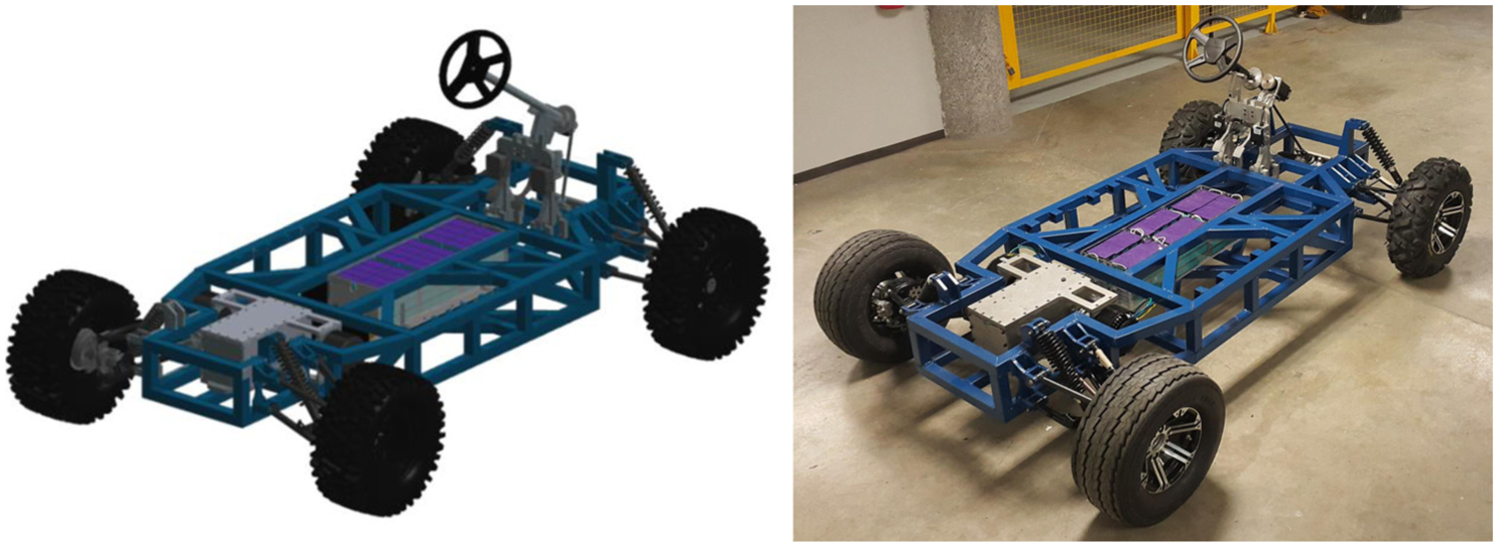
CAD model (left) and physical prototype (right).
Control system
The central part of the control system is the controller that comprises eight cores of 32 bits each (P8X32A Propeller). The controller is responsible for three main functions: (1) data acquisition, (2) sending signal to actuators, and (3) communication with the mobile device. Figure 3 provides a visual representation of the shared signals among the components of the control system: (a) signals from sensors (dashed line), (b) signals to actuators (double line), and (c) serial communications (dotted lines).

Components of the control system and communications signals.
Data acquisition
The focus is on two main sources of information from the electric vehicle: (1) the speed of the electric motors of the powertrain and (2) the position of the steering wheel. The powertrain of the EvTec is composed of two electric motors. A first mechanical differential operates as a double-input single-output (DISO) mechanical device, using as mechanical inputs the shafts of each of the electric motors. This double motor powertrain increases the energy efficiency. The output angular speed of the powertrain is shown in equation (1), where

By obtaining data about the speed of the electric motors of the powertrain, the speed of the electric vehicle (

The angular speed of the electric motors is monitored at its output shaft. Hall sensors are installed in the proximity of each axle in such a way that six magnets attached to each axle, produce an on/off signal in the sensor. This information is transmitted to the digital inputs of the microcontroller. The microcontroller calculates the time between pulses and translates it into an estimated angular speed

The position of the steering wheel is measured by a distance sensor in one of the tie-rods of the steering system. When the steering wheel rotates, the tie-rod performs a linear movement, which is transmitted from the distance sensor to the microcontroller.
Actuators
The actuators play critical roles in (1) the acceleration of the electric motors of the powertrain and (2) the angular displacement of the stepper motor of the steering system. For the acceleration of the motors, it is necessary to supply a voltage signal (0–5 V) to the accelerator input in the electric motor controllers. The vehicle controller provides this signal in the form of pulse width modulation (PWM). The acceleration of the motors is controlled by the variation of the duty cycle and the application of a low-pass filter.
For the control of the angular displacement of the steering actuator, voltage pulses have to be supplied to the step pin in the controller of the stepper motor. To control the direction of the angular displacement, an on/off voltage signal has to be supplied to the direction pin in the stepper motor controller.
Communications
There are two critical communication systems: (1) vehicle controller and mobile device communication and (2) mobile device and remote server communication (Figure 4).

Communications of the mobile device, microcontroller, and remote host.
The controller of the vehicle has two channels (Rx and Tx) that are used to set up a serial port. The serial port communicates in full-duplex operation that has a universal asynchronous receiver/transmitter with baud rate of 115,200. The communication can be achieved by WLAN, Bluetooth, or USB, which are well-known connectivity options. For this proof of concept, a USB cable was used, and the mobile device has the WLAN/Bluetooth options free for any other function. The app manages the sending and receiving functions using individual threads executed at fixed rates.
The app installed in the mobile device also manages the communication with a remote host using Wi-Fi. The app sends information to a webpage stored in the remote host. The webpage obtains the URL parameters using the PHP command GET and stores them in a database created in MySQL. The stored webpage in the remote host communicates back to the mobile app using the PHP command ECHO. The communication is managed in the mobile device by sending data at a fixed rate using an individual thread.
Levels of connectivity
This research project considers three levels of operating conditions to validate the performance of the connectivity for vehicle control purposes. This approach allows one to gradually increase the complexity of the connectivity and control system to potentially be included in the framework of the final goal: achieve autonomous navigation. The levels were designed to showcase the capabilities of the system. Specifically, the designed system allows to recovery of the monitored data in the remote host, which will enable a comparison against expected results concerning the dynamical behavior of the magnitude of two key factors in the vehicle control: the vehicle speed and the angle of the steering wheel. While Level-1 is implemented in this work, Level-2 and Level-3 are beyond the scope of the current experimentation and are considered only in a conceptual stage at this point.
Level-1
In the first level (Level-1), the vehicle controller generates a signal to control the accelerator of the powertrain (

Flow diagram of the signals for Level-1: remote monitoring situation.
Level-2
Level-2 consists of basically the same processes of Level-1, but the remote host analyzes the information received and decides whether or not to issue a warning, for example when a speed limit is violated. This level resembles a situation of V2X in which different entities can receive and feed relevant information to the vehicle, using Internet as the medium. The warning is transmitted to the mobile device using Wi-Fi and from there to the vehicle controller by the USB cable. The process is repeated continuously (Figure 6).

Flow diagram of the signals for Level-2, which represents a V2X situation.
Level-3
For Level-3, the control signals are generated in the remote host and transmitted to the vehicle controller through the mobile device. This level resembles a full remote control situation (Figure 7).

Flow diagram of the signals for Level-3, which represents a remote control situation.
Results
The plots presented in Figures 8–14 exemplify Level-1 of the concept presented in this research. These figures present control signal data (
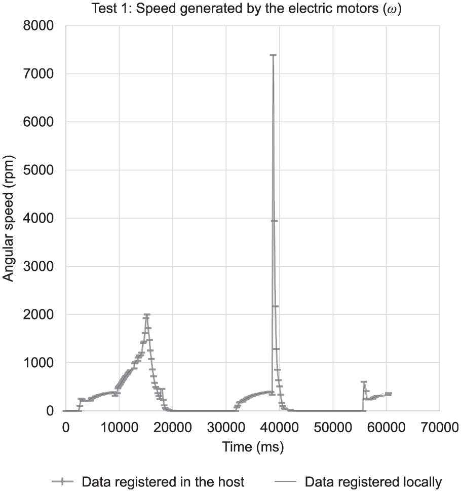
Plot of the angular speed registered in the host and in the Android device.

Plot of the signal of the accelerator registered in the host and in the Android device.

Plot of the signal sent to the stepper motor of the steering system registered in the host and in the Android device.

Plot of the signal of the sensor installed in the rack of the steering system registered in the host and in the Android device.
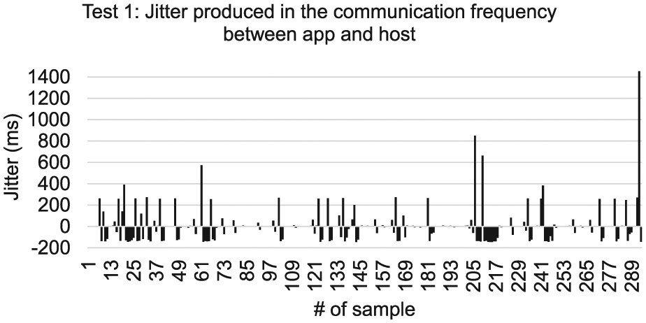
Plot of the jitter produced in the frequency of communication between the host and in the Android device.

Plot of the angular speed registered in the host and in the tablet where a remarkable error in the register if time is present.

Plot of the values of the angular speed registered in the host and in the tablet where no data loss is present besides the error in the register of time.
Figure 9 shows a plot of
Figures 10 and 11 provide plots of
Figure 12 shows the jitter produced in the communication cycles between the app and the remote host. The jitter was calculated measuring the actual duration of the cycles and subtracting the programmed cycle time (200 ms). As can be seen, besides the good results reproducing the values of the signals in the remote host, the communication rate has significant variations which help to explain the differences between the plots reconstructed from the data from the mobile device and the data downloaded from storage in the cloud. The maximum jitter was as high as 1400 ms, with an average of 4.86 ms and a standard deviation of 149.33 ms.
Figure 13 shows an example of a case (Test 2) in which there was a probable error in the register of the time at which the values were received either in the mobile device or in the remote host. As can be seen, the plots appear out of phase, with the data registered locally (mobile device) being delayed. Despite this situation, the integrity of the data sent was very good as can be seen in Figure 14 where the same data (
Discussion
The results presented here demonstrate that Level-1 of conditions of operations can be satisfied with the proposed concept of connectivity. However, more testing and further analysis are necessary to provide confirmation of reliable performance.
The results presented were obtained using a relatively stable Wi-Fi network in an indoor environment. Communication using 4G and in outdoors situations have yet to be tested. The remote host used for this work was a low-cost commercial host, not optimized for cloud monitoring and remote operations. While the concept presented here relies on an open architecture involving a microcontroller and several sensors with non-conventional communication protocols, the concept can be expanded to be used in addition to the on-board diagnosis (OBD) system of a vehicle. Simple changes may be implemented to communicate the vehicle computer to a mobile device and use the mobile device to perform operations in the cloud like online monitoring, as presented here.
While Level-2 and Level-3 of operation conditions planned for this concept were not displayed in the previous results, it is clear that they can be developed with the basis provided by this work. For example, the remote host can be easily programmed to echo warnings, once a reliable and stable communication is established between host and tablet. It is very important to clarify that even with the short response times shown here, some conditions should be met before the remote host may be able to communicate complex control commands, especially those related to safety. Among those conditions are the stability of the Internet connection, communication latency, and range of geographic coverage. For the moment, the best strategy is to implement the control algorithms locally and use the connectivity as support information.
The testing carried on in this work was not subjected to the effects of network congestion. This phenomenon can have an impact on the results and further testing is required. In the scenario in which more vehicles use connectivity, network congestion is an expected challenge to overcome. A similar situation can be faced with security. While this aspect is out of the scope of this work, the unauthorized access to the network is a major issue that should be solved before this concept can have a wider adoption.
Conclusion and future work
This article introduced the EvTec electric vehicle concept. The vehicle was designed and constructed in a modular way to allow the testing of different technologies, as well as customization. HMI is achieved by the use of an app programmed in a mobile device with Android OS.
The app was communicated with a microcontroller to form the AbCE. The microcontroller shares data with the tablet, which was used to provide an interface between the vehicle and the user, as well as a gate to obtain connectivity. The connectivity of this concept was divided into three levels. Level-1, consisting in vehicle monitoring and cloud back-up, was tested with data obtained in real time from the steering wheel movement and acceleration of the electric motors.
Future work consists in the testing of Level-1 connectivity in various conditions, closer to real driving operation. Other subsystems of the vehicle can be added to the monitoring function, for example, status of battery charge. Future work will also focus on achieving Level-2 and Level-3 connectivities, which consist respectively, in monitor the vehicle and remotely send warnings or control commands to the vehicle. This connectivity could help provide support for local sensors and processing in the case of autonomous driving.
Footnotes
Academic Editor: Tian Han
Declaration of conflicting interests
The author(s) declared no potential conflicts of interest with respect to the research, authorship, and/or publication of this article.
Funding
The author(s) disclosed receipt of the following financial support for the research, authorship, and/or publication of this article: This research was supported by CONACyT (the Mexican National Council for Science and Technology) and by the research group Automotive Consortium at Tecnológico de Monterrey.