
Abstract
Based on the Reynolds-averaged Navier–Stokes equations of relative coordinates and the RNG k-ε turbulence model, using our SIMPLE algorithm, we performed numerical simulations for an AP1000 nuclear main pump model with water as the medium. By changing the size of the tongue blend in the annular casing, seven different schemes were designed. Three-dimensional numerical simulations were conducted for the flow within the pump under various settings, and the flow characteristics of the annular casing using different tongue blends were obtained. The results show that for different operating conditions, there is a specific tongue blend that optimizes pump performance. Based on the calculation results, a larger tongue blend leads to a larger flow rate. Off-design conditions caused flow instability, which in turn caused the tongue blend to have a certain impact on the performance of the impeller. However, the performance of the pump was not primarily affected by changes in the impeller performance, but was instead affected by the performance of the annular casing, which was itself affected by tongue blend. When changing the tongue blend, the change in static pressure and total pressure of the annular casing was larger under the condition of 0.6Qd and was smaller under the conditions of 1.0Qd and 1.4Qd. The turbulent kinetic energy in the annular casing changed mainly in the tongue impact zone and outlet diffuser under the condition of 1.0Qd; furthermore, the turbulent kinetic energy in the whole of the annular casing demonstrated significant changes under the conditions of 0.6Qd and 1.4Qd.
Introduction
The nuclear main pump, the “heart” of a nuclear island, is the only component of a nuclear power plant equipment requiring high-speed operation. Since the nuclear main pump is subject to high temperatures, high pressures, and high levels of radiation fluid, its performance and stability is critical to the safety of the entire nuclear power plant. As an important energy conversion unit of the nuclear main pump, the performance of the annular casing has a great influence on the performance of the whole pump. Taking into account the safety, pressure, and forging performance, 1 the annular casing comprises the volute of the nuclear main pump. Previous studies of the volute have mostly focused on spiral casings. R Barrio et al. 2 studied the flow field distribution in a spiral casing. Choi 3 investigated the flow characteristics of a circular casing in a centrifugal pump of low specific speed. M Xue and Y Piao 4 studied the influence of the tongue blend on the shape evolution of the vortex in the volute. Furthermore, the influence of the section area and section shape on the flow field and performance of the spiral casing have also been studied.5–7 The influence of the volute structure on the radial force and performance of the centrifugal pump have been studied.8,9 R Zhu et al. 10 investigated the influence of the annular casing outlet contraction angle on the performance of the nuclear main pump. N Zhang et al. 11 determined that a sloped volute effectively reduces the high pressure pulsation level in a spiral volute. DZ Wu et al. 12 found that enlarging the structural size of the volute can improve the flow state of the nuclear main pump outlet diffuser. However, at present, there is still a need to further study the flow characteristics affected by annular casing of the nuclear main pump.
In this study, an AP1000 pump model was used as the research object. Starting with the overall structure of the main pump as the foundation, a more reasonable geometric model was established. With the aid of computational fluid dynamics (CFD) numerical simulations, the flow field in the main pump was calculated for different tongue blends. Through data analysis, the influence of various tongue blends on the flow characteristics of annular casing was obtained.
Model description and numerical calculation
Model parameters
In this study, an AP1000 nuclear main model pump was selected as the research object. The model pump ratio coefficient was λ = 0.4. The model pump design parameters were as follows: head H = 17.8 m, flow rate Q = 1144.7 m3/h, and rotational speed n = 1750 r/min. The working medium was water.
Model description and mesh generation
Figure 1 shows a sketch of the flow-through components of the model pump. The model pump was composed of five main flow-through parts, including the suction section, impeller, guide vane, annular casing, and outlet section. In order to obtain the flow characteristics of the annular casing with different tongue blends, 10 sections were established within the annular casing. The flow characteristics of the annular casing were expressed by the pressure and turbulent kinetic energy of those 10 sections. The position of each section is shown in Figure 2.

Sketch of flow-through components structure of model pump.

Sketch of annular casing sections: (a) two-dimensional sketch and (b) three-dimensional sketch.
The computational domain was divided into a mesh using the pre-processing software Gambit. Because of the complex structure of the nuclear main pump, the grid was divided into the main pump fluid field using an unstructured tetrahedral mesh with strong adaptability to the complex boundary. The steady flow was predicted for the design condition with six meshes having 1.53 × 10⁶ to 8.74 × 10⁶ elements. A grid-independent test curve is shown in Figure 3, where it can be seen that the head of pump with 6.25 × 10⁶ or more elements had no significant difference less than 0.5%. The number of elements for each flow-through part is shown in Table 1. The computational domain mesh is shown in Figure 4.
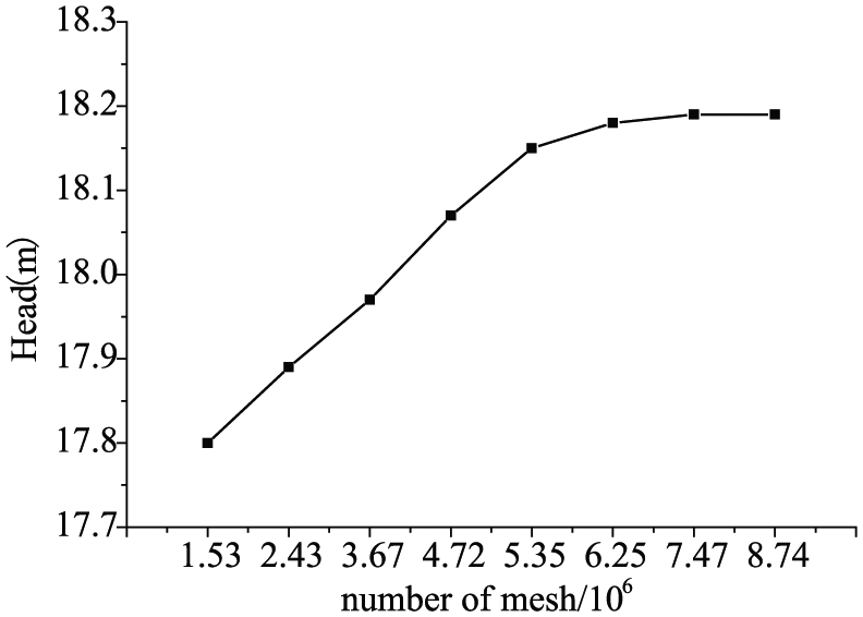
Grid-independent test curve.
Detailed mesh information.

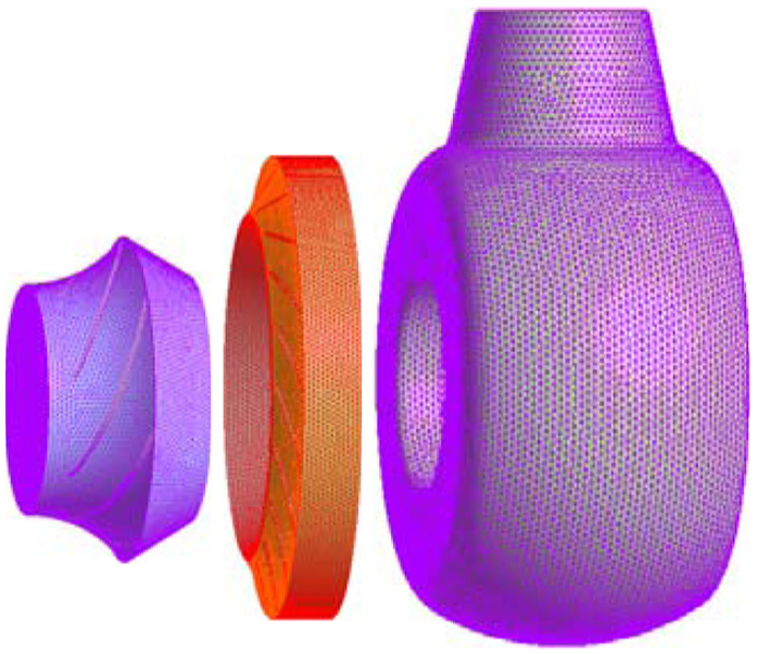
Meshing of computational domain.
Numerical simulation and scheme design
The complicated flow field was analyzed using Reynolds-averaged Navier–Stokes (RANS) equations in conjunction with governing equations as follows:
Continuity equation

Navier–Stokes equation

where u is the flow velocity,
The Reynolds stress values were modeled using the renormalization-group (RNG) k-ε turbulence model, which considers the flow separation and vortex flow in the process of the pump flow and has high precision in its handling of the high strain rate and flow of the streamline. 13 The pressure and momentum equations were coupled using the SIMPLE-consistent (SIMPLEC) algorithm with a high-resolution scheme. The finite volume method was used to discretize the governing equations, using a second-order scheme used for the advection term. The iterations were continued until the average residual error dropped to 0.0001. The convergence of the numerical results was evaluated by monitoring the residual values and the pump outlet pressure. 14
The calculated boundary conditions were set as follows: the velocity inlet was specified at the suction section inlet with uniform normal flow running into the pump. The outflow outlet was specified at the outlet of the outlet section. The stationary walls were set as no slip walls. The steady incompressible flow field calculation was carried out using the multiple reference coordinate system. The impeller was defined as a rotating reference frame, with a rotational speed of n = 1750 r/min, and the remaining components comprised the stationary reference frame.
Figure 5 shows a sketch of the model pump computational scheme. The annular blend is the transition region between the annular basin of the volute casing and the outlet diffuser. The tongue blend R of the annular casing is shown in Figure 5. The value of R was changed to study the influence of the tongue blend on the flow characteristics of the nuclear main pump’s annular casing. The values of R used in this study were 0, 12, 24, 36, 50, 65, and 80 mm. At the same time, in order to facilitate the analysis of the flow characteristics of the annular casing with different tongue blends, the center plane of the outlet diffuser of the annular casing was defined as the A-A plane, as shown in Figure 5.
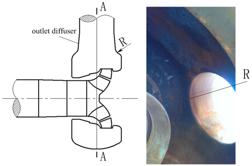
Sketch of model pump computational scheme.
Results analysis
Reliability demonstration
The model test of the tongue blend R = 50 mm model pump was carried out on a four-quadrant test bench, as shown in Figure 6.

Sketch of experimental setup.
The following formulas were applied to predict the head and efficiency. The calculation method of the head is shown in formula (3)

where H is the head of the pump,
The calculation method of efficiency is shown in formula (4)

where
The numerical simulation results of the model pump were compared with the experimental results, and the comparison results are shown in Figure 7. As can be seen in Figure 7, the calculated values of the model pump were in good agreement with the experimental results. Under the design conditions, the head error was not more than 4.39%, and the efficiency error was not more than 3.55%. For both small and large flow rate conditions, as a result of deviating from the design conditions, the flow angle as well as the impeller and guide vane setting angles were mismatched, which resulted in lower accuracy and an increase in head and efficiency calculation errors. However, the head error was less than 8.74%, and the efficiency error did not exceed 8.12%. Therefore, the numerical calculations showed high precision and were validated for application within the research work.

Characteristic curves of model pump.
Analysis of the tongue blend effect on performance under different operating conditions
The influence of tongue blend on the pump performance under different operating conditions
Figure 8 shows the curves of the pump performance for different tongue blends. It can be seen from the figure that the tongue blend had a definite impact on the pump head and efficiency. For the three operating conditions with changes in the tongue blend R, the trends of pump head and efficiency were the same. Under each operating condition, with an increase in the tongue blend R, the pump head and efficiency first increased and then decreased. When R = 0 mm, the performance of each operating condition was at its worst. With an increase in the tongue blend R, the pump performance gradually improved. For the condition 0.6Qd, the pump head and efficiency reached maximum values at R = 36 mm; for the condition 1.0Qd, the pump head and efficiency reached maximum values at R = 50 mm; for the condition 1.4Qd, the pump head and efficiency reached maximum values at R = 65 mm. It is known that for different operating conditions, the tongue blend R has a certain influence on the pump performance. From the calculation results, the optimal tongue blend R increased with increasing flow rate.

Curves of pump performance at different tongue blends.
Influence of the tongue blend on the impeller performance under different operating conditions
The following formulas were applied to predict the impeller head and impeller efficiency. The calculation method of impeller head is shown in formula (5)

where
The calculation method of impeller efficiency is shown in formula (6)

where
Figure 9 shows the curves of impeller performance for different tongue blends. It can be seen from Figure 9 that under different operating conditions, the influence of the tongue blend on the impeller performance was different.

Curves of impeller performance at different tongue blends.
Under the specified design condition, there was little influence on the head and efficiency of the impeller. However, under 0.6Qd and 1.4Qd conditions, the influence of the tongue blend on the performance of the impeller increased, especially for 0.6Qd. This was because in the design condition, the blade setting angle and flow angle were well matched; in off-design conditions, the change in the flow angle resulted in poor matching, thus causing the impeller to demonstrate unstable flow phenomena. Overall, regarding the change in the tongue blend, the trends of the impeller head and impeller efficiency were similar. Meanwhile, the impeller head and efficiency deviated within a very limited range. Hence, it is more likely that these parameters are insensitive to changes in the tongue blend.
Influence of tongue blend on hydraulic loss under different operating conditions
The following formulas were applied to predict the hydraulic loss of both the guide vane and annular casing. The calculation method of the guide vane hydraulic loss is shown in formula (7)

where
The calculation method of annular casing hydraulic loss is shown in formula (8)

where
Figure 10 shows the curves of the hydraulic loss for different tongue blends. On the whole, the tongue blend had a minimal impact on the hydraulic loss of the guide vane, but had a substantial impact on the hydraulic loss of the annular casing. It can be seen from Figure 10 that under different conditions, with an increase in the tongue blend R, the total hydraulic loss and the hydraulic loss of the annular casing had the same trend. Therefore, the change in tongue blend can be considered as the main reason for the change in total hydraulic loss. From the hydraulic loss magnitude, it can be seen that with an increase in flow rate, the total loss first increased and then decreased; the hydraulic loss of the guide vane decreased and then increased; finally, the hydraulic loss of the annular casing increased gradually. When R = 0 mm, the hydraulic loss of the annular casing was at its maximum under each operating condition. This was mainly because when the tongue blend R = 0, the transition boundary between the annular basin and the outlet diffuser was poor, which resulted in outlet diffuser vortex flow. This unstable flow increased the hydraulic loss of the annular casing. For the 0.6Qd condition, the hydraulic loss of the annular casing reached a minimum value when R = 36 mm; for the 1.0Qd condition, the hydraulic loss of the annular casing reached a minimum value when R = 50 mm; for the 1.4Qd condition, the hydraulic loss of the annular casing reached a minimum value when R = 65 mm. These results corresponded well with the changes in pump head and efficiency according to tongue blend. It can be seen that changes in the impeller performance were not primarily responsible for the performance of the pump, but instead, changes in the performance of the annular casing caused by the tongue blend were primarily responsible for the performance of the pump.

Curves of hydraulic loss at different tongue blends.
Influence of tongue blend on the pressure distribution under different operating conditions
Influence of tongue blend on the static pressure distribution under different operating conditions
Figure 11 shows the curves of the static pressure of the annular casing for different tongue blends. On the whole, the static pressure of the annular casing differed under different operating conditions. The static pressure of the annular casing first increased and then decreased along the main flow direction under the 1.0Qd condition; furthermore, it decreased gradually in the annular basin and then increased in the outlet diffuser under the conditions of 0.6Qd and 1.4Qd. In particular, the static pressure in the outlet diffuser increased rapidly under the 0.6Qd condition. This was thought to be related to the distribution of the flow field in the annular casing. With the change in the tongue blend, the change in the annular casing static pressure was larger under the 0.6Qd operating condition, and the change in static pressure was small under the 1.0Qd and 1.4Qd operating conditions. Compared with other tongue blends, when R = 0 mm, the static pressure of the annular casing reduced. This was related to the unstable flow in the outlet diffuser.

Curves of static pressure of annular casing at different tongue blends.
Influence of tongue blend on the total pressure distribution under different operating conditions
Figure 12 shows the curves of total pressure of annular casing for different tongue blends. It can be seen from Figure 12 that the influence of tongue blend on the pressure distribution in the annular casing differed under different conditions. For each operating condition, the tongue blend had a certain effect on the pressure distribution of the outlet diffuser. In particular, when R = 0 mm, the pressure on the section of the outlet diffuser suddenly dropped, and in all of the off-design conditions, the degree of drop enhanced. Compared with the outlet diffuser, the influence of the tongue blend on the pressure distribution in the annular basin was relatively small.

Curves of total pressure of annular casing for different tongue blends.
Influence of tongue blend on the turbulent kinetic energy of the annular casing under different operating conditions
Figure 13 shows the curves of turbulent kinetic energy of the annular casing for different tongue blends. It can be seen from Figure 13, along with the changes in tongue blend, that the turbulent kinetic energy of the annular casing changed, but the extent of their variations differed under each operating condition. With respect to location, the turbulent kinetic energy of the annular casing was most significantly affected by tongue blend in sections 1, 9, and 10, representing the tongue impact zone and outlet diffuser in the 1.0Qd condition. Furthermore, the change in turbulent kinetic energy of annular casing occurred across the entire annular casing for the 0.6Qd and 1.4Qd conditions. In particular, when R = 0 mm, because of the change in the flow field, the turbulent kinetic energy increased much more rapidly in the outlet diffuser.

Curves of turbulent kinetic energy of annular casing at different tongue blends.
Influence of tongue blend on the streamlines of annular casing under different operating conditions
Figure 14 shows the streamlines of the annular casing for different tongue blends. It can be seen from Figure 14 that for each operating condition, a change in the tongue blend corresponded to the presence of a vortex in the annular casing. However, the number and position of vortexes were different for each tongue blend. It was found that there was a certain effect on the distribution of the flow field in the annular casing. When the tongue blend R = 0 mm, the left side of the outlet diffuser displayed an obvious vortex. For the off-design conditions, the vortex area significantly increased. Therefore, the flow in the outlet diffuser was determined to be sensitive to the operating conditions.
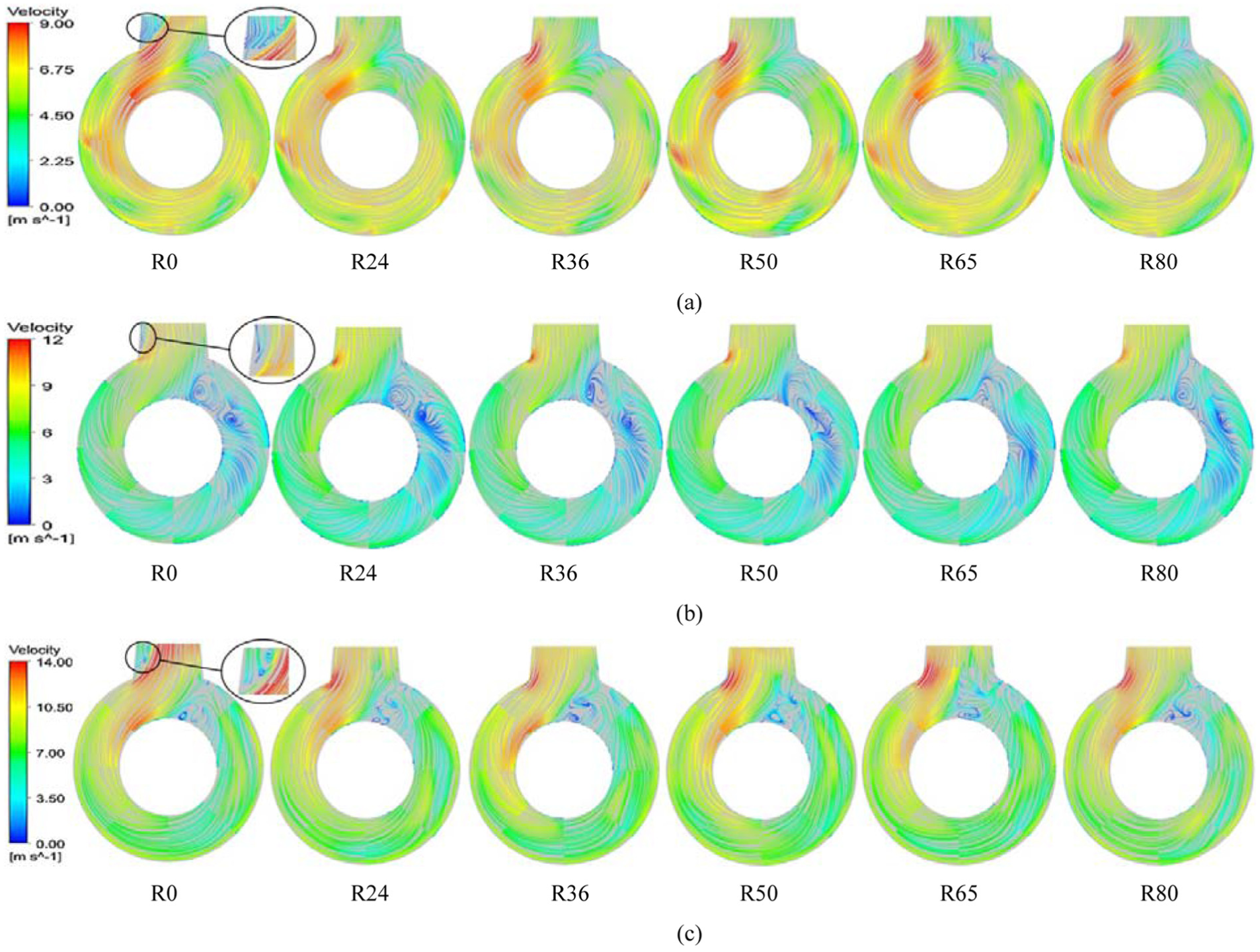
Streamlines of annular casing at different tongue blends: (a) 0.6Qd, (b) 1.0Qd, and (c) 1.4Qd.
Conclusion
Under different operating conditions, there was a specific tongue blend R that optimized the pump performance. The optimal tongue blend R increased with increasing flow rate. Under different operating conditions, the performance of the annular casing caused by the change in the tongue blend was primarily responsible for the performance of pump. The tongue blend had a certain influence on the flow characteristics of the annular casing, and the influence was found to be greater when the flow rate was smaller.
Footnotes
Academic Editor: Yangmin Li
Declaration of conflicting interests
The author(s) declared no potential conflicts of interest with respect to the research, authorship, and/or publication of this article.
Funding
The author(s) disclosed receipt of the following financial support for the research, authorship, and/or publication of this article: This work was supported by the National Natural Science Foundation of China (grant nos 51369015 and 51469013).