
Abstract
Automatic road markings recognition is important for the research of intelligent vehicle which is used for both automotive navigation and advanced driver assistance system. In most previous researches, the markings such as lane have been used for localizing and serving the vehicle along the road. However, in fact, the markings such as guide arrows and warnings are necessary for automotive navigation. Therefore, this article presents an automatic road markings recognition method based on support vector machine to reduce the impact of external environment such as viewpoint, brightness, and background. In which, the input vector comprises four improved Hu moments and two affine invariant moments obtained from reconstructed image. The presented method has been tested with experiment images, and the results show that the accuracy of recognition can be reached over 97% and time consumption per frame is 0.26 s. It is clear that the proposed method has strong potential effectiveness to be applied for intelligent vehicle systems application.
Keywords
Introduction
Machine vision has greatly promoted the development of intelligent vehicle (IV)-related technology and effectively reduced the traffic accidents caused by driver’s fatigue and distraction. However, on the other hand, machine vision has shown limited success because of its reliability in real driving scenarios. Considering road markings recognition as the core issues in IV research field, this article presents an approach with information fusion for road markings recognition. The presented method is capable of classifying the markings with minimum false alarms and miss-detections.
Road marking recognition is a challenging task for real-time applications, which has become a research highlight for decades. Many studies have been conducted on this topic, but many of them are often restricted to a simple target such as lane mark. Partial of the achievements are already commercially available in vehicles. At present, the research can be roughly classified into monocular and binocular methods according to vision information obtained.
In monocular research, road markings are always recognized in two-dimensional images. On one hand, the characteristics of brightness difference between markings and background are often applied. Different classification methods are proposed. Wang et al. 1 presented a lane detection and tracking system based on lane features extraction method and the Gaussian sum particle filter. In order to overcome the shortcomings of traditional algorithms such as not adaptive to changing environments and hard selection of threshold, Xiao et al. 2 proposed an adaptive structured learning method based on road markings detection algorithm. In which, a structured random forest was learned to classify each image patch first and then the contextual information of the images and the structural information of the labels were effectively exploited to reduce the ambiguity.
Tang et al. 3 proposed a method for real-time lane detection and anti-rear-end collision system for drivers. The work uses a monocular camera to estimate the distance with the forward vehicles. The system can distinguish lane departures if the vehicle is too close with the forward vehicle. However, in these methods, the lane mark is often approximated with line model of Hough transform (HT) method. When the markings do not have the characteristics of line shape appearance especially the curve lane and other traffic markings, the methods cannot work properly. Traditionally, B-snake curve fitting is used for this purpose. 4 But it does not work well at the truncation points of the images because this method always uses vanishing point to extrapolate the line segment which represents lane data. So, Gupta and Merchant 5 proposed an algorithm to achieve lane detection applying K-means clustering method to report data in a manner suitable to create a solvable map. The presented method overcomes the shortcomings of B-snake as it did not depend on the perspective transform.
In binocular research, the stereo pairs make it possible that the road markings are reconstructed in three-dimensional (3D) spaces. Soheilian et al. 6 presented an approach to road marking reconstruction using stereo pairs acquired by a mobile mapping system in a dense urban area. In the research, zebra crossings and dashed lines were studied. The other authors use a sequence of stereo pairs for road marking reconstruction.7–11 The advantage of these methods is that the marking information can be obtained in an absolute coordinate system. But on the other hand, the binocular method is always time consuming and unsuitable for real-time applications.
At present, most of the related methods mentioned above are only researched in detail in theoretical and model approaches, but there is still a long distance to go from theory approaches to practical applications. The automatic extraction of road markings from images is a complex problem due to the following issues: (1) partially damaged or occluded markings, (2) complex road environment and marking contrasts, and (3) perspective distortion. Thus, to fuse possible features from the image extraction is essential for making an accurate recognition effectively.
Support vector machine (SVM) has proved its success in many research fields including both data classification and pattern recognition. 12 It shows very resistance to over-fitting problem and achieves high performance in recognition problems.13–15 These successful researches motivate us to apply SVM in the road markings detection for natural environments. Therefore, this article aims to establish a road marking recognition model. In which, SVM is used as a classifier to recognize the markings which types they belong to. To achieve this, in this article, measurable visual characteristics such as improved Hu moments and affine inconvenience moments will be identified.
The rest of this article is organized as follows: first, the system overview including on-board image acquisition system and sketch map of this article is described; second, the perspective distortion of the image is corrected using non-linear mathematical model; then, within the established area of interest (AOI), the combined feature vector used for SVM is obtained; finally, auto-detection of road markings with the presented method has been tested with experiment and the conclusions are derived respectively.
System overview
On-board system setup
To acquire the markings image accurately, it is essential to set up an on-board image acquiring system. Figure 1 shows the configuration for this article’s research, which include a camera mounted on the windshield and an on-board computer. When system starts, the camera captures the front environment image and transmits it to the computer real time. Then, the proposed method of this article is conducted.
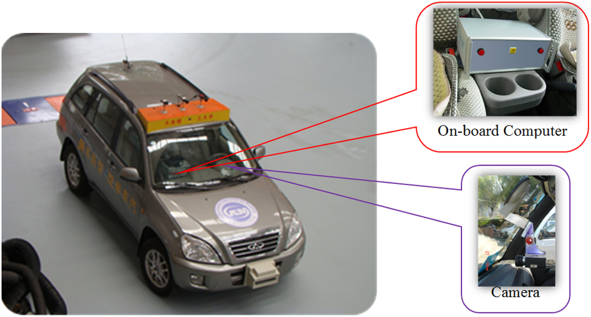
Hardware configuration for the proposed method.
Overview of the proposed method
Considering the practical applications required with performance, the presented method refined road marking recognition and is shown in Figure 2.

Sketch of the road marking recognition.
First, perspective distortion correction process is conducted and then the image preprocessing steps are applied. Second, the region of AOI which limits the road markings search area to a region as small as possible is defined. In this area, most of the “noise” is excluded. Then, invariant combined vector of candidates for SVM recognition are extracted. In the following section, the main steps for the presented approach are described in detail.
Perspective scene reconstruction
In photography and cinematography, perspective distortion is determined by the relative distances between the viewer and the target. For road marking recognition, such a distortion would result in visual deviation and have influences on the image information extraction. Therefore, this article adopts a non-linear mathematical model to conduct the reconstruction process. According to Zhang et al., 16 given an image point (x, y) and its 3D corresponding point (X, Y, Z), the relationship between them is

where C1–C8 are undetermined coefficients which can be determined with four couple points by undetermined coefficients method.
With equation (1), indoor and outdoor simulation experiments were conducted, and the results are shown in Figure 3. In which, the red circles indicate the control points used in the scene reconstruction process. Based on our experience, it is important to note that when the control points are distributed over the entire image, a better reconstruction effect can be obtained. On the contrary, when distributed within the local area, the effect decreases.

Simulation experiments.
Some conclusions can be obtained through the above experiments: First, the accuracy of image reconstruction depends on the distribution of the control point. Second, the road markings are reconstructed to their relative spatial location.
Lane marking detection
In this step, the lane detection phase includes three steps: feature extraction, lane modeling, and parameter estimation. Taking into account that most of the road markings are located in the current lane, we conduct the road marking recognition in the current lane region.
Lane marking feature extraction with one-dimensional entropy segmentation
In information theory, entropy is used for measuring the uncertainty problems associated with random variable. This term is often referred to Shannon entropy. In general, the value of entropy information reaches maximum at the border between target and background.
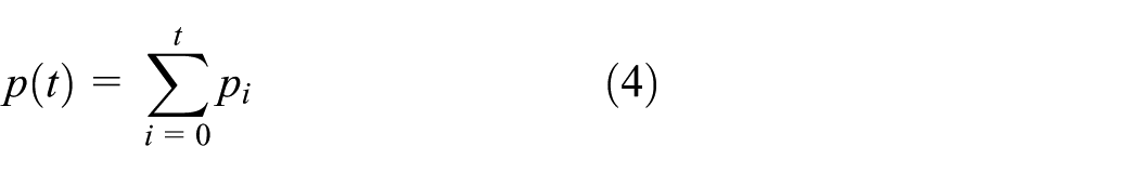
Given the image with gray level L (0 < L ≤ 256), the probability of pixels with gray level i is

where fi denotes the number of pixels with gray level i and M, N denotes the image dimension.
Assumed t as the threshold for segmentation, the target and background entropies are

where
then the optimal threshold is

With the algorithm mentioned above, examples for feature extraction are shown in Figure 4. In which, the first row is the original reconstruction images, the second row is the images after preprocessing with gray balance, the third row is the binary image using one-dimensional (1D) entropy, the fourth row is the results with area-filtering algorithm, and the fifth row is the gradient image using Canny operator. The experiment shows that the marking edge features are extracted completely (the fifth row). Within the image processing process, the gray balance algorithm was introduced to enlarge the difference between foreground and background gradation thereby enhancing the image contrast. The area-filtering algorithm was conducted to reduce some unwanted image information for marking detection.
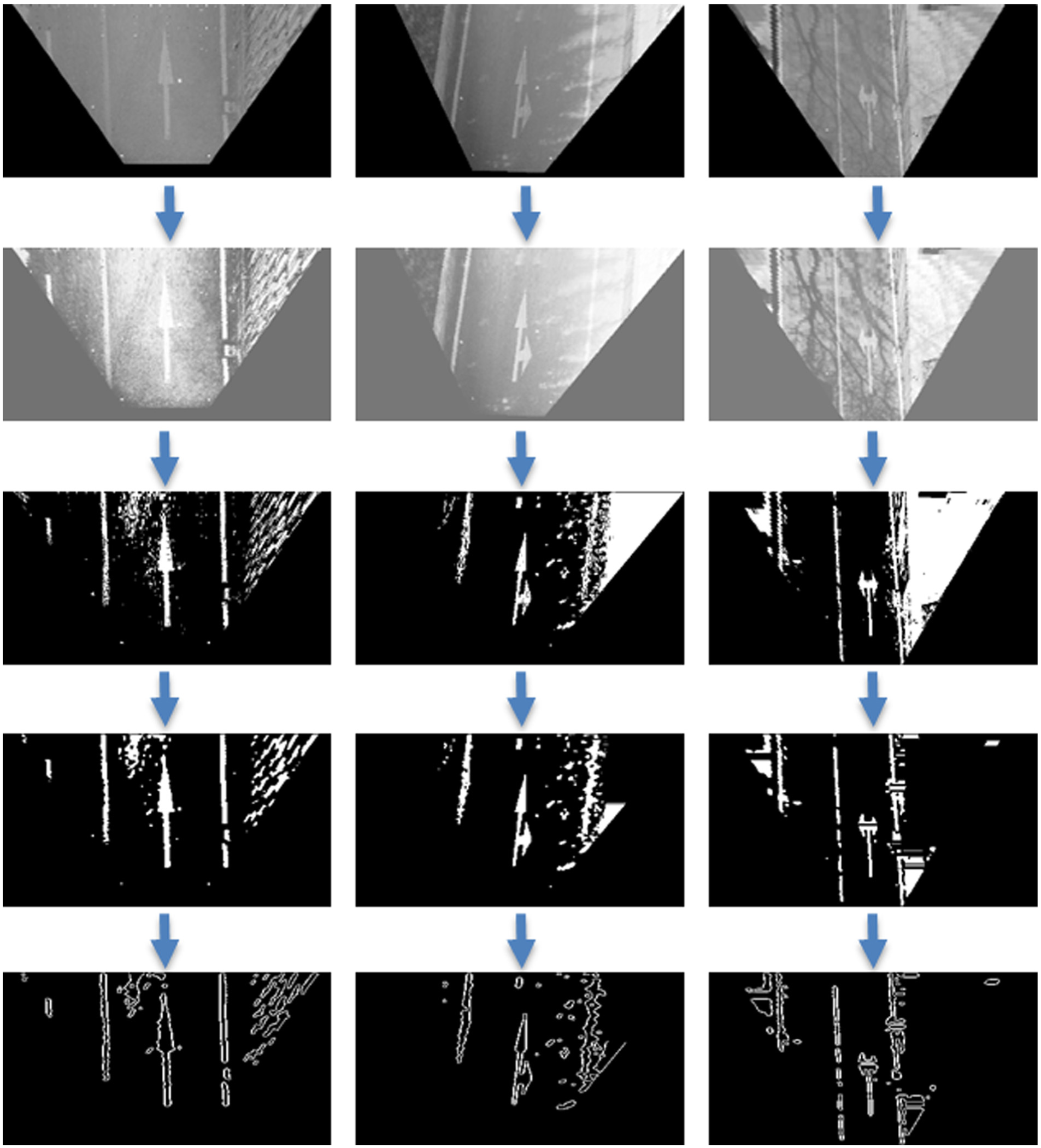
Lane feature extraction results.
Lane marking detection
In this article, HT is used for lane marking detection. The HT method is widely used in the lane marking detection which is not sensitive to noise, so it can handle the condition that target is incomplete or be covered partially. 17
The lane-related parameters are extracted with HT method. In this article, the AOI is divided into two regions; the origin of coordinates is set at the bottom line center which is shown as Figure 5.

HT coordinate systems.
For the left and right regions, given y = mx + b as the line equation. HT method is conducted with the following formula

where (r, θ) denotes the vector from the origin to the nearest point of y = mx + b. In r − θ space, every line in the space xoy can be transformed to a point. In the same way, every point in xoy can be transformed to a line. The relationship between (r, θ) space and (r, θ) space is shown as Figure 6. Hough line transformation is the method which is based on this duality and the process is that calculating the line intersection in r − θ space (shown as (r0, θ0) in Figure 5) and then determining the line with the maximum point in the parameter space.
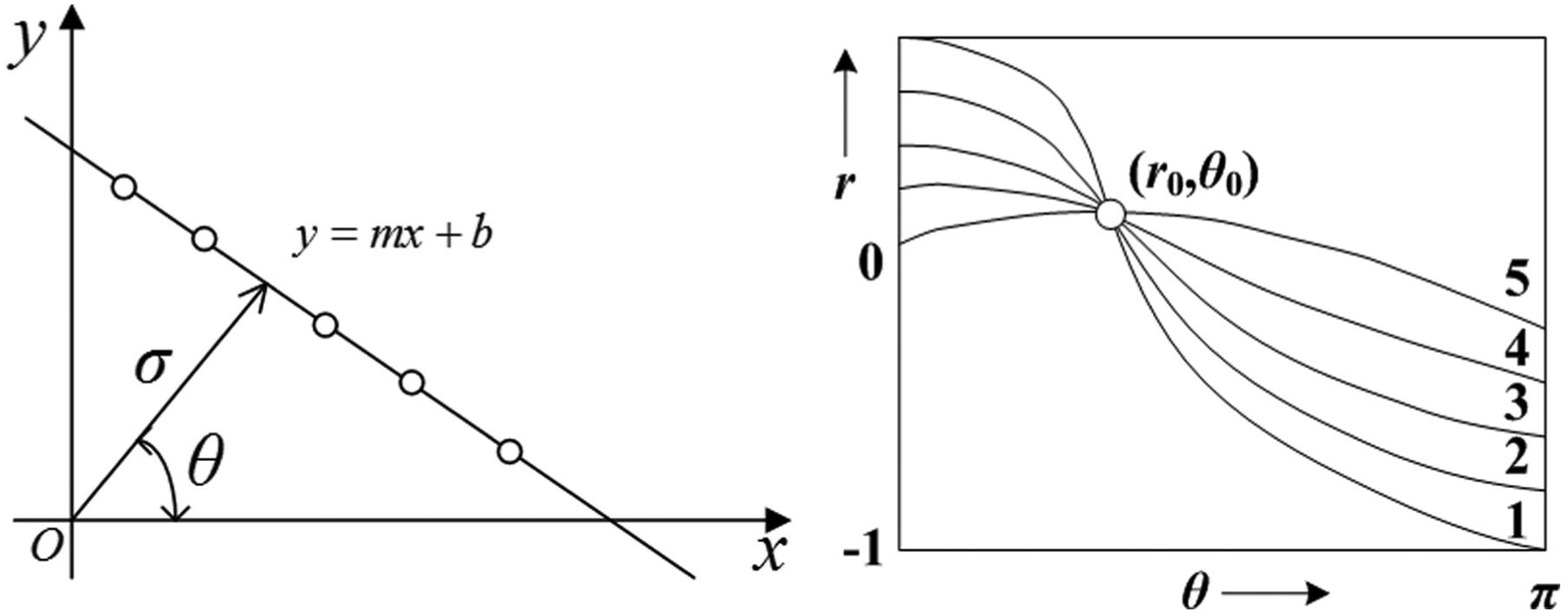
Hough transform.
With the method described above, lane markings in Figure 4 are detected which are shown as Figure 7.

Lane marking detection results.
With the AOI established, the image is segmented with 1D entropy algorithm. In experimental result shown as Figure 8, region index algorithm is used for recognizing the markings. Then, the target with maximum index length is considered as the possible candidate. In which, the first column is the segmentation images in the AOI, the second column is the images after noise filtering, and the third column is the region index images for the candidate markings.

The candidate target detection.
Features extraction
Road marking has many characteristics including circle, rectangle, texture feature, and so on. Hu moment and affine invariant moment are the two important features in pattern recognition because they are not sensitive to translation, stretch, and rotation. Thus, this article adopts the combined-moment invariants (including four Hu moments and two affine invariant moments) as the main features used for road marking recognition.
Improved Hu invariant moment
Hu presented a theory of two-dimensional moment invariants for plane geometric figures and gave the descriptors of seven invariant moments in the literature. 18 In discrete space, the moment with p + q order and central moment are described as

where

It is clear that the moments have the invariance properties with translation and rotation. However, this property would be affected with scale factor. 19 Given the image coordinate (x, y) and the coordinate (x′, y′) with scale factor ρ, the central moment is

This equation describes the relationship between the central moment

where
Affine invariant moment
Affine invariant moment is derived from the algebraic invariant theory, which has the invariance characteristic with translation, shearing, scaling, and rotation. Flusser and Suk 20 presented three affine moment descriptors with the invariant property
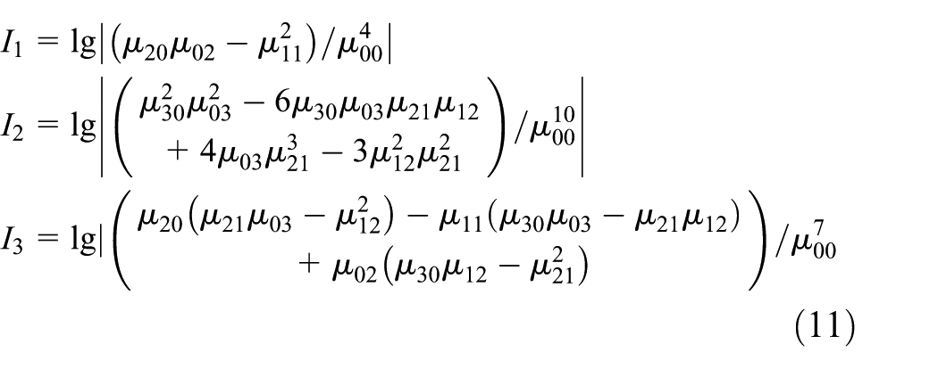
where
Features dataset construction
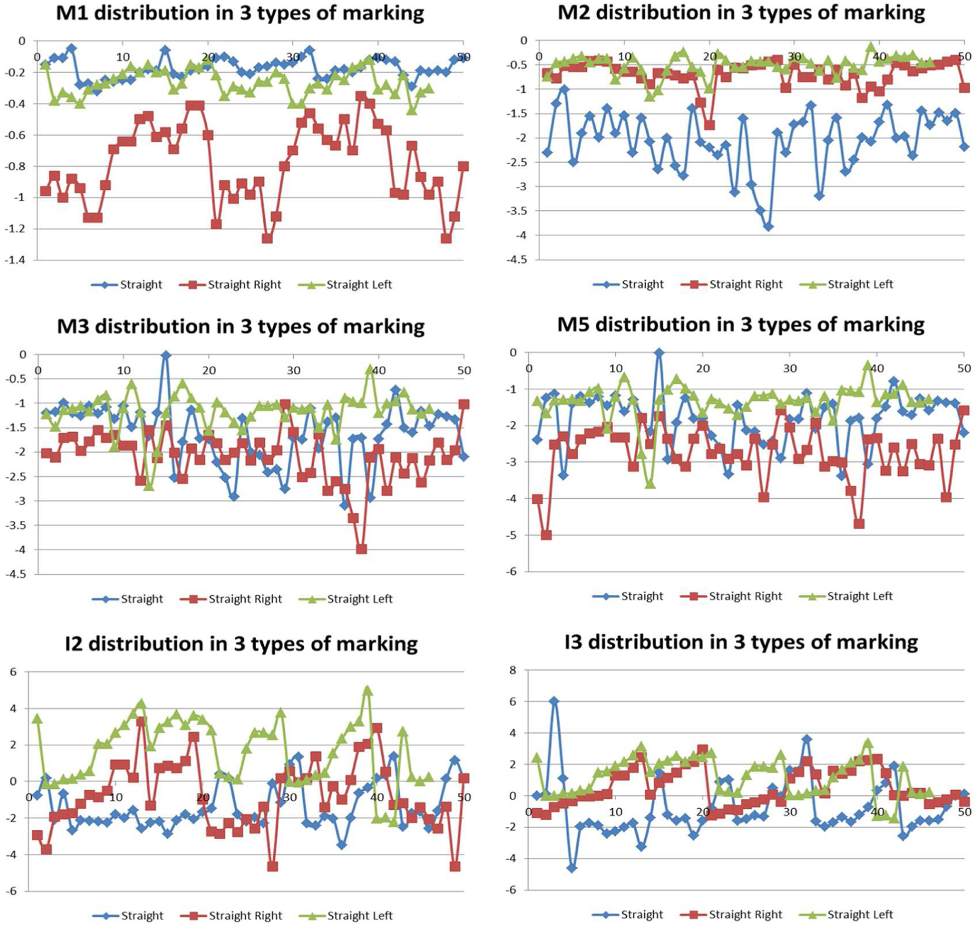
In this phase, a feature vector reflecting the difference between markings is essential for road markings recognition. Thus, this article extracts the features M1–M5 and I1–I3 with three types of road markings, including straight, straight right, and straight left markings. Then, the comparison analysis is conducted, and the results are shown in Figure 9. In which, because the difference of M4 and I1 is not obvious between the three types, the comparisons of them are not listed.
Statistics of the features with different road marking.
From the above analysis, some important cues can be drowned. First, M1 and M2 are different obviously between the marking samples. Thus, they are considered the main important features for identifying process. Second, shown as features M3, M5, I2, and I3, although the markings recognition cannot be conducted with a certain feature, we can recognize the marking with the combination of all features obtained. Thus, in this article, the vector used for SVM is constructed as follows

Road marking recognition based on SVM
SVM is introduced by Cortes and Vapnik 21 in 1995. It is a powerful method which has proved its success in many research fields ranging from freeway incident detection, 22 target recognition, 23 bus arrival time, 24 facial expression recognition, 13 and handwritten character recognition 14 to intrusion detection. 25 Here, only a very brief introduction to SVM is described.
Given the dataset with instance label (xi, yi), where xi∈Rn and y∈(−1,1) l , the solution of SVM is the result with the following problem
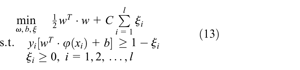
where vectors xi is mapped into a higher dimensional space by kernel function Φ. C > 0 denotes a penalty parameter which is used for evaluating the error of instance.
With Lagrange multiplier
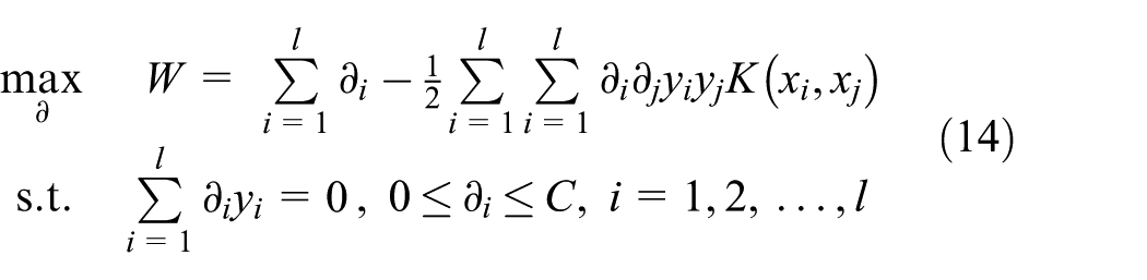
Then, the decision function of SVM is
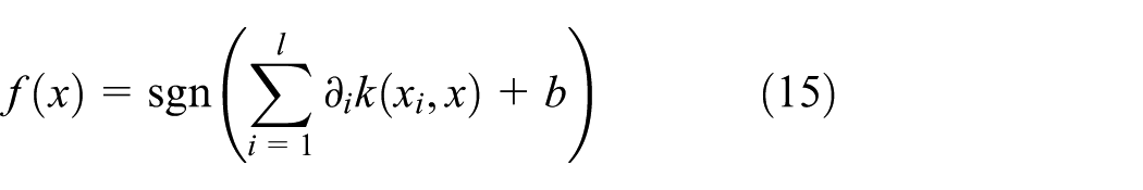
In this article, the presented SVM model will be trained with feature vectors extracted from image. Then, it is used for the classification process of road markings with test dataset. The structure of the presented SVM model is shown in Figure 10. In which, V1…Vs denote the combined feature vector extracted with equation (12) in section “Features dataset construction.” All the features are mapped to the high-dimensional space through the kernel function K and classified with linear classification criteria. Finally, the decision result is given by the discriminant function f(x).
Structure of the SVM model for the road marking recognition.
Based on the SVM model, radial basis function (RBF) kernel function is selected. With the grid search strategy on the training dataset, the parameters of SVM can be obtained:
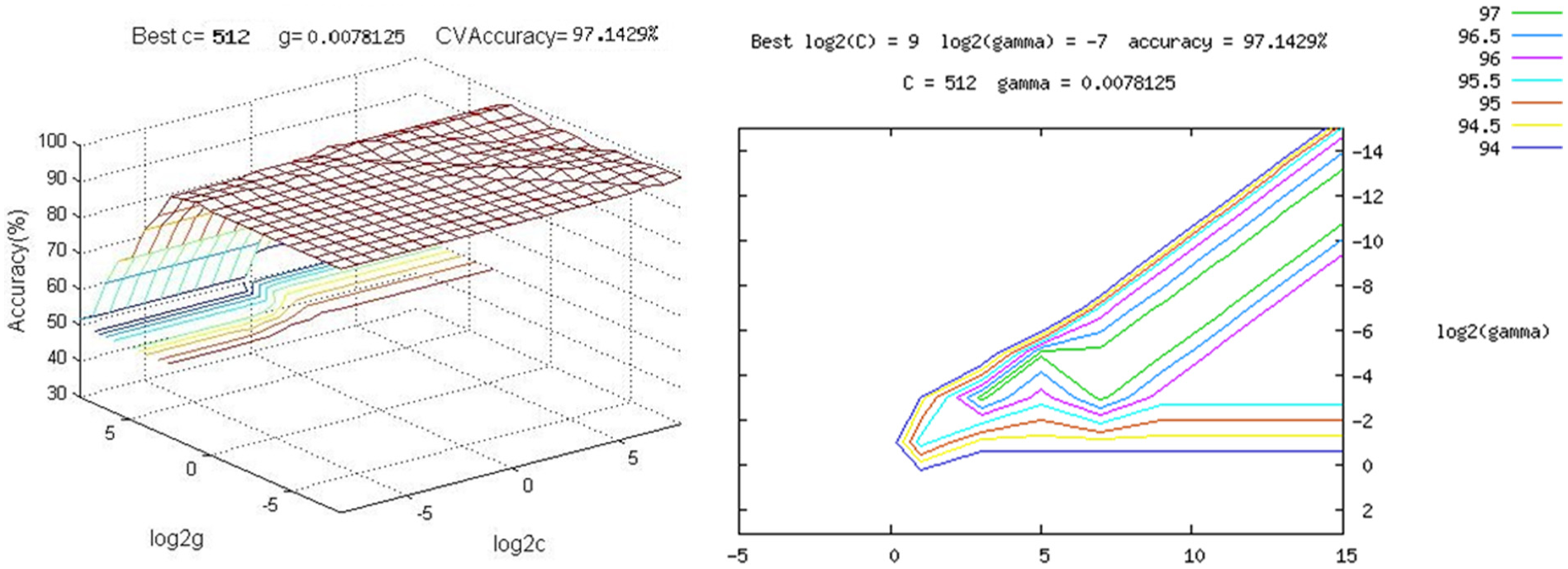
The SVM model for marking recognition training process.
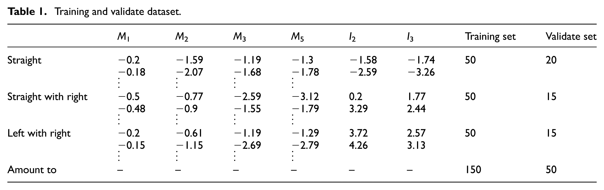
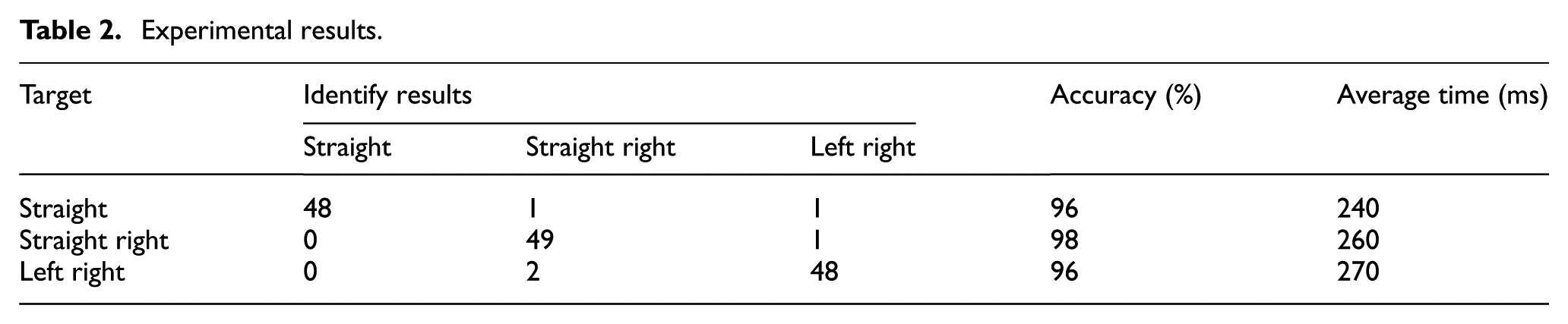
Table 1 shows the partial training and validate data in the SVM training process. The road marking recognition experiment results are shown in Table 2. It is clear that the recognition rate could reach 97% and the time consumption per frame is 0.26 s. Therefore, it indicates that the proposed method has strong potential effectiveness to be applied to the intelligent driver assistance system.
Training and validate dataset.
Experimental results.
Conclusion
Road marking recognition in real driving environments is an important task for the vehicle autonomous navigation and the robotic location. This article presents a road marking recognition method to reduce the impacts of environment changes such as viewpoint, brightness, or background changes. The method adopts SVM for classifying the obtained markings from each other. In which, the features vector includes four improved Hu moments and two affine inconvenience moments. Experimental results show that the proposed method for road marking recognition in natural environment has good reliability and robustness.
Footnotes
Academic Editor: Tao Feng
Declaration of conflicting interests
The author(s) declared no potential conflicts of interest with respect to the research, authorship, and/or publication of this article.
Funding
The author(s) disclosed receipt of the following financial support for the research, authorship, and/or publication of this article: This project was partially supported by National Natural Science Foundation of China (51509031 and 51675077), China Postdoctoral Science Foundation (2015M581329), and the Fundamental Research Funds for the Central Universities (3132016009).