
Abstract
A dual-chamber hydro-pneumatic suspension, a modified version of the traditional hydro-pneumatic suspension, can provide enhanced isolation performance. In this article, we use two very different theories, nonlinear vibration theory and fractional calculus theory, to analyze the characteristics of a dual-chamber hydro-pneumatic suspension. We find that both the storage stiffness and damping coefficient show a strong dependency on the excitation frequency. The effect of various suspension parameters on storage stiffness and damping coefficient is discussed in detail using numerical simulation. We also performed experiments that confirm the validity of the mathematical expressions for both the storage stiffness and the damping coefficient.
Keywords
Introduction
For several decades, due to their nonlinear stiffness, pneumatic vibration isolators have been widely used for vibration isolation in many engineering structures such as vehicle suspensions, high-precision manufacturing equipment, and seat suspensions, which were gradually improved.1–16
A dual-chamber hydro-pneumatic (DCHP) suspension system was reported in El-Tawwab 1 that provides improved suspension performance while avoiding a major increase in complexity and cost. The structure was shown schematically, and a simplified linear mathematical model was employed to describe the suspension dynamics. Simulation results in the time domain show that the twin accumulator suspension leads to significant improvements over the conventional passive suspension system. Erin et al. 2 point out that a dual-chamber pneumatic isolator would benefit from an accurate mathematical model to improve the design of vibration isolation tables because significant deviations were found between predicted and observed behavior in several studies. The article introduced a modified model for a pneumatic isolator taking into account the effect of the diaphragm. As a result, the accuracy of the predictions using the modified model was better. Sun et al. 3 describe the structure of a pneumatic suspension with an auxiliary reservoir, and the test results show the characteristic of varying damping and stiffness. A compact variable stiffness and damping shock absorber was designed, prototyped, tested, and modeled in his later research. 4 The intergeneration projection genetic algorithm (IP-GA) method was used to identify model parameters. Lee and Kim 5 adopt a pneumatic spring suspension with a similar structure to the one described in Erin et al., 2 which is to be used for vibration isolation for precision manufacturing instruments. A mathematical model capable of high precision considers thermodynamic behavior of air in chambers, fluid-dynamics of the air flow in capillary tubes, and the dynamic characteristic of a diaphragm. It acts as an effective tool to describe the behavior of the DCHP suspension. The complex stiffness derived from a set of motion equations shows a dependency on both the excitaion frequency and the excitation amplitude. The validity of the expression for the complex stiffness was confirmed through experiments. The two terms, storage stiffness and loss factor, are the parameters to be determined for designing a dual-chamber pneumatic isolator. In Lee and Kim’s 6 later research, the transmissibility from base excitation to the displacement of the spring mass was derived. To minimize the transmissibility at the resonance frequency and to retain good isolation performance for higher frequencies, the effect of the parameters on transmissibility was discussed in detail. Similar studies were described in Porumamilla et al. 7 and Holtz and van Niekerk 8 with the aim to reduce the seat effective amplitude transmissibility (SEAT) value used for evaluating the isolation performance of the seat suspension. Other contributions from Nieto and colleages,9–11 Liu and Lee, 12 Pu et al., 13 Li et al., 14 and Chai et al. 15 are helpful to understand the frequency and amplitude characteristics of a DCHP suspension.
The article consists of six sections. The structure and components are presented in section “Structure of the DCHP suspension.” Nonlinear isolators have attracted increasing attention recently because all isolators are inherently nonlinear. Furthermore, the use of nonlinear stiffness and damping enables superior isolation performance. The harmonic balance method (HBM) is one of the most commonly used tools for nonlinear vibration analysis. Preliminary studies indicate that both the storage stiffness and the coefficient damping are frequency-dependent. Modeling and analysis of the DCHP suspension were carried out using the HBM described in section “Modeling and analysis of the DCHP suspension using nonlinear oscillation theory.” In section “Modeling and analysis of the DCHP suspension based on fractional order calculus theory,” a model of the DCHP suspension was developed based on fractional calculus. We then compared the two modeling methods. In section “Experiment results and discussion,” experiments for varying parameters are described. The measurements confirm the analytical expression for the equivalent storage stiffness and the damping coefficient.
Structure of the DCHP suspension
A schematic of the DCHP suspension is shown in Figure 1. The suspension system consists mainly of five components. A cylinder that supports the spring mass is located between the vehicle body and the front or rear wheel. A piston rod can move axially inside the suspension cylinder. The piston divides the cylinder into two chambers: the compression chamber and the extension chamber. When the piston travels up and down, the oil flows through the valve block. As a result, the main damper can provide a damping force to reduce the oscillations of the vibration system. Two accumulators, which act as elastic elements, can be found in the DCHP suspension. These two accumulators are linked via a variable orifice, that is, an adjustable throttle valve. The valve opening of the adjustable throttle valve can be regulated to adjust the damping coefficient between the accumulators. The effect of additional damping on both storage stiffness and damping coefficient of the isolation system will be discussed in the following sections.

Schematic of the dual-chamber hydro-pneumatic suspension.
Modeling and analysis of the DCHP suspension using nonlinear oscillation theory
Modeling of the pressure of the rebound chamber
Figure 1 shows the flow of oil in the cylinder. The geometrical change of volume of the rebound chamber due to the moving piston is balanced by the flow of oil through the piston valve and the compression or expansion of oil in this chamber. The damping force is typically calculated using fluid mechanics theory assuming that the used oil is incompressible. Lang 17 considered the compressibility of oil in a mathematic model for the shock absorber. Both simulation and experiment indicate that the compressibility of oil is one of the major causes of the damper’s nonlinear dynamic behavior, such as hysteresis loops that occur at higher excitation frequencies.
The compressibility

where V and
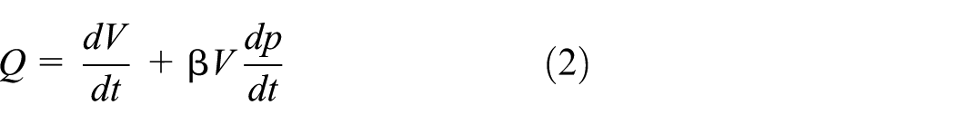
The motion of the main piston, x, is enforced by the test rig actuator. As a result, a certain amount of oil,
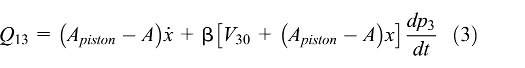
where
Modeling of the pressure in the accumulators
The compression chamber is connected to the main accumulator (see Figure 1). As a result, the pressure in the compression chamber and the main accumulator is the same. The gas volume change in the main accumulator is caused by the geometrical change of the volume of the compression chamber during the motion of the piston. Apart from the oil flowing into the rebound chamber, there is another volume
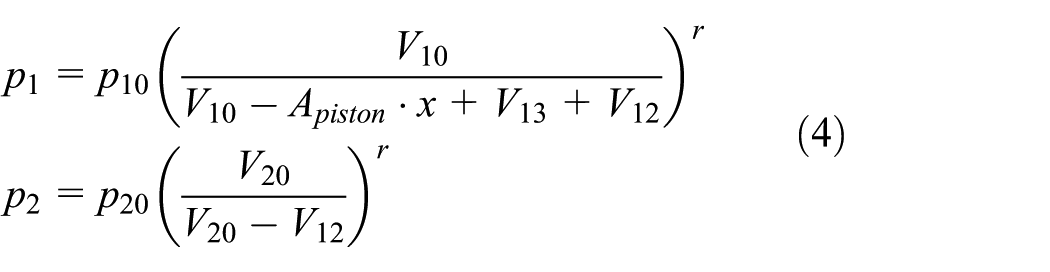
Here,
The oil-compressibility factor for the rebound chamber is often considered during the modeling process. However, for the compression chamber, similar to the mono-tube damper, 19 the oil compressibility is negligible compared with the compressibility of the nitrogen gas enclosed in diaphragm accumulators. As a result, we can simplify as follows

In other words, the pressure model of the compression chamber can be modified using the simplification assuming that the oil is incompressible and both accumulators have the same initial pressure,

Modeling of the damping force of the throttle valve
The volumetric flow rate Q for a liquid through an orifice is generally described by the equation
The liquid damping force in the adjustable throttle can be expressed as the quadratic term of the velocity, plus a linear term

Simplification of the dynamic characteristic of the DCHP suspension
According to the above-discussed modeling of the components, the transmitted force of the DCHP suspension for a base excitation x is given by
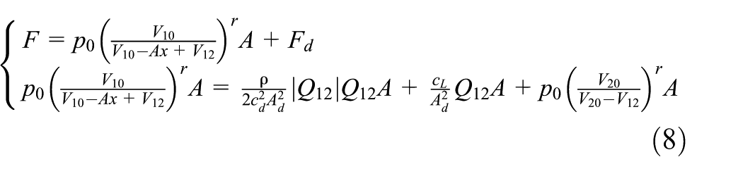
where
Here,
For simplicity, the storage stiffness of the accumulator fits the linear model in earlier research. However, the linear model is unable to describe the effect of the nonlinearity of a restoring force on the equivalent stiffness, damping coefficient, and isolation performance for a DCHP suspension. Because it is very difficult to solve equation (9) analytically for high orders of

The quartic term in the simplified storing force model means that the DCHP suspension is a hardening isolation system in the direction of the compression, but a softening isolation system in the direction of the extension. Overall, it is a hardening system in a complete isolation cycle, which is one of the advanced properties of a hydro-pneumatic suspension.
Solution of the equations for motion for harmonic excitation
Mixed-parity nonlinear oscillation problems, especially isolators with a nonlinear restoring force with an additional quartic term, have been studied previously. Lu et al. 20 transform the isolation system with nonlinear restoring and damping forces into a standard duffing isolation system. They derive the displacement transmissibility using the HBM, which is considered suitable for both weak and strong nonlinear vibration problems. The simulation results show that the quartic term for the restoring force affects the static equilibrium position of the oscillation system.
The first-order HBM is used to solve equation (10) using the assumption of the approximate solutions

The bias terms
Squaring and adding the last two equations of equation (12) yield

where
For a given sectional area of the piston rod A, the initial pressure
Equivalent stiffness and damping coefficient
According to equation (10), the linear model for the DCHP suspension under base excitation can be given by

and the transmitted force using a Laplace transformation of equation (14) is

The real part of the transmitted force represents the storage stiffness. The imaginary part is the loss stiffness, 13 which actually denotes the damping characteristic of the DCHP suspension. The dynamic stiffness and the damping coefficient can be written in the following form

Although the spring and the damping component are linear, equation (16) shows that both the dynamic stiffness and the damping coefficient have a frequency-dependent characteristic. The dynamic stiffness
Using the concepts of equivalent stiffness and damping coefficient,21,22 the equivalent stiffnesses of the main and additional accumulators are


The adjustable throttle valve with mixed damping has an equivalent damping coefficient

Here,
The equivalent stiffness and damping coefficient for the DCHP suspension are given by

Unlike the dynamic stiffness and damping coefficient for the DCHP suspension with linear elastic and damping components, both
The characteristics of the dynamic stiffness and damping coefficient for the linear and nonlinear DCHP suspension in the frequency domain are shown in Figure 2.

Computational simulation of the (a) storage stiffness and (b) equivalent damping coefficient for different types of damping behavior.
According to Figure 2(a), the storage stiffness curve follows an “S” shape in the frequency domain. The stiffness remains a small constant but increases with increasing frequency to a certain level. When the curve becomes flat, the stiffness reaches its own upper limit. The minimum and maximum storage stiffness of the nonlinear DCHP suspension are deduced by setting

Based on the expressions above,
For the sake of studying the effect of additional nonlinear damping, the maximum as well as the minimum storage stiffness for different types of nonlinear additional damping are set to be equal. Figure 2(a) shows storage stiffness curves indicating similar behavior but not exactly identical. The stiffness curve is much steeper under the influence of the additional damper with hardening flow resection behavior.
The damping curve of the linear model shows a reverse-“S” shape in the frequency domain (see Figure 2(b)). However, affected by the frequency-dependent characteristic, the curve for quadratic damping follows a bell-shape. It is the hardening damping that causes the transcendence for the damping coefficient in the frequency range that
The additional damping determined by the degree of opening the throttle valve is essential for the isolation performance of the DCHP suspension. Adjusting the throttle valve mainly affects the secondary damping coefficient. Therefore, some simulation results are shown for different values of
Computational simulation of the (a) storage stiffness and (b) equivalent damping coefficient for different values of
We find that the storage stiffness curves shift along the frequency axis for different
Modeling and analysis of the DCHP suspension based on fractional order calculus theory
Modeling of the DCHP suspension
This section describes a very different modeling method for the dynamic behavior of the DCHP suspension.
Some mechanical isolators, 23 such as engine mounts and viscoelastic dampers, are made of viscoelastic materials that have the same frequency-dependent characteristic. The properties of viscoelastic materials have been extensively studied in their own material-specific field. Both a theoretical analysis and experiments of mechanical isolators were carried out to study viscoelastic materials. Modeling is done assuming that a certain number of springs and dampers are combined into a mechanical network with the specific series-parallel logic, which is a common method to describe and analyze the behavior of the viscoelastic material. 24 The Kelvin–Voigt model consists of a spring and a damper connected in parallel, while the Maxwell model uses them in series. The Zener model consists of a spring connected with a Kelvin model in series, or a spring connected with a Maxwell model in parallel. It is commonly used to describe the dynamic behavior of viscoelastic isolators. Two types of Zener models are shown schematically in Figure 4(a) and (b).

The schematic diagram of Zener models: (a) Kelvin form and (b) Maxwell form.
Adopting the linear Zener model (Kelvin form) to describe the dual-chamber pneumatic suspension, VM Ryaboy 16 derived the expressions for both the dynamic stiffness and the loss stiffness. Moreover, the transmissibility for a single degree of freedom vibration system installed with the dual-chamber pneumatic suspension from base excitation to spring mass displacement could be established mathematically, together with an analysis of the effect of parameters on the transmissibility. To improve the accuracy of the frequency-dependent behavior described by conventional models, fractional calculus was used. The fractional models have been used as modified versions of these traditional linear models. They were shown to be powerful tools.24–26 Fractional models have the ability to model the viscoelastic isolators mathematically using only a small number of parameters. More specifically, they use only a single equation instead of the set of differential equations used in traditional models.
T Pritz 25 summarized prior studies and put forward a fractional derivative model with only four parameters to describe the variations of the dynamic properties of the viscoelastic materials for a wide frequency range. In later studies, 26 a new version of the fractional derivative model characterized by five parameters was introduced. It describes even more accurately the asymmetrical loss factor peak as well as the dynamic behavior for high frequencies.
For viscoelastic dampers, Makris and Constantinou 27 proposed a fractional derivative Maxwell model, which was validated by comparing simulation results for dynamic stiffness with experiment observations.
The general form of the standard linear viscoelastic model is given as 28
where
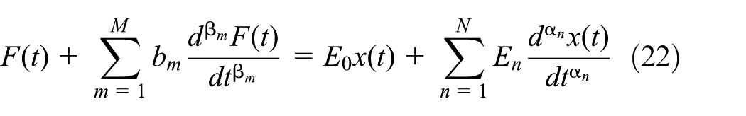
By keeping only the first-order fractional derivative of

The

Storage stiffness and equivalent damping coefficient
According to the fractional Fourier transform theory, the Fourier transform of the fractional derivative of order α has the same form as the one of the integer derivative order

Here,
where

where the real part,

Assuming the fractional factor

Comparison of the simulation results of two different models
Equations (20) and (29) are the general expressions for the equivalent stiffness and damping coefficient of the nonlinear suspension system. However, the storage stiffness

According to the simulation results for the different
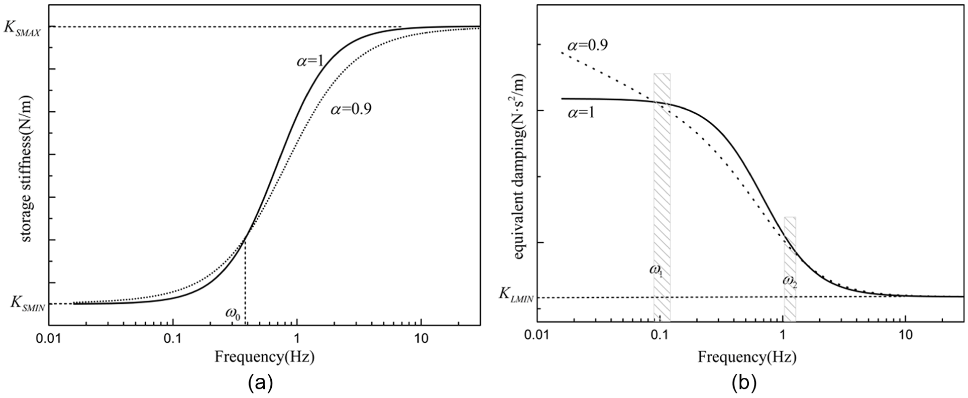
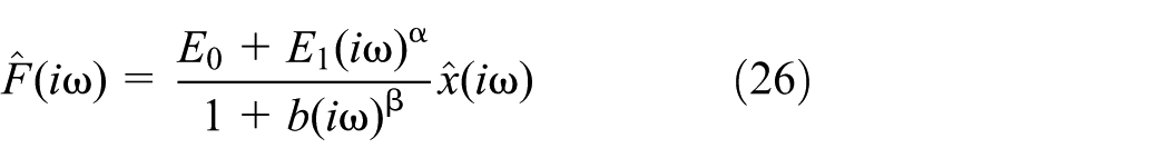
Computational simulation of the (a) storage stiffness and (b) equivalent damping coefficient for different values of the fractional derivative order α.
Both minimum and maximum storage stiffness can be calculated using equation (29) (a) at

A set of equivalent curves obtained by varying the fractional derivative
Experiment results and discussion
Set-up of experiments
Two completely different theories are applied to describe the dynamic behavior of the DCHP suspension. The validity of equations (20) and (29), which are compatible with nonlinear vibration theory and fractional calculus, respectively, will be verified through the following experiments. To reduce complexity, the valve disk was removed from the piston, so that the damping force produced by main damper can be ignored. The adjustment of the additional damping coefficient will be realized via the throttle valve.
The DCHP suspension is installed in the test setup, which consists of a computer-controlled electro-hydraulic shaker platform (Japan Saginomiya), frame, S-type load cell, and a linear variable differential transformer (LVDT) displacement sensor. For the transmitted force measurements, the bottom of the DCHP spring is mounted onto the shaker head and the top is linked with the frame. The excitation frequency varies between 0.1 and 9 Hz. The displacement input signal, which is a sine wave with fixed amplitude (10 mm), is measured with an LVDT displacement sensor. The signal acquisition of the force and displacement data is accomplished using a data acquisition instrument (COINV INV3060V). Photos of the experimental device are shown in Figure 6.

Photos of the experiment device.
Experimental results
In the experiment, the frequency of the excitation sine wave and the opening of the throttle valve are the parameters that were adjusted. All parameters for the DCHP spring used in simulations and experiments are listed in Table 1.
Parameters of the DCHP suspension.

The force (F) provided by the DCHP suspension consists of frictional force (Ff), damping force

Here,
Computational simulations in the frequency domain were carried out, and the simulation results were compared with the experiment (see Figures 7 and 8).

Comparison of storage stiffness and equivalent damping coefficient between experiment and simulation for throttle opening level 1: (a) storage stiffness based on nonlinear vibration theory, (b) equivalent damping based on nonlinear vibration theory, (c) storage stiffness based on fractional calculus, and (d) equivalent damping based on fractional calculus.

Comparison of storage stiffness and equivalent damping coefficient between experiment and simulation for throttle opening level 2: (a) storage stiffness based on nonlinear vibration theory, (b) equivalent damping based on nonlinear vibration theory, (c) storage stiffness based on fractional calculus, and (d) equivalent damping based on fractional calculus.
The behavior of the DCHP suspension strongly depends on the excitation frequency. Although the predictions for equivalent damping show some discrepancies with the experimental measurements for the low-frequency ranges, the behavior of the DCHP suspension is accurately predicted for the whole frequency range using the models based on both nonlinear vibration theory and fractional calculus theory.
Conclusion
This article describes a traditional hydro-pneumatic suspension connected with an additional accumulator and an adjustable throttle valve. Nonlinear vibration theory and fractional calculus theory were used to model the DCHP suspension. The expression for the storage stiffness and the equivalent coefficient was deduced and comprehensive simulations and experiments carried out. The frequency-dependent characteristic can be summarized as follows:
In the low-frequency range, both accumulators act as elastic elements, and the storage stiffness is numerically equal to the stiffness values of two springs in series. With increasing excitation frequency, the additional accumulator gradually stops functioning, resulting in only the main accumulator providing the elastic force.
An additional damping coefficient that can be controlled by a throttle valve is the most important parameter that causes the storage stiffness curve to shift along the frequency axis and affect the peak value of the equivalent damping.
The validity of two complete different models describing the behavior of the DCHP suspension was confirmed. Good agreements between analytical equations and experiment results were obtained.
We conclude that the performance of vibration systems can be improved significantly and optimized through suitable selection of the parameters in the DCHP suspension.
Footnotes
Academic Editor: Rahmi Guclu
Declaration of conflicting interests
The author(s) declared no potential conflicts of interest with respect to the research, authorship, and/or publication of this article.
Funding
The author(s) received no financial support for the research, authorship, and/or publication of this article.