
Abstract
The absolute nodal coordinate formulation is a computational approach to analyze the dynamic performance of flexible bodies experiencing large deformations in multibody system dynamics applications. In the absolute nodal coordinate formulation, full three-dimensional elasticity can be used in the definition of the elastic forces. This approach makes it straightforward to implement advanced material models known from general continuum mechanics in the absolute nodal coordinate formulation. As, however, pointed out in the literature, the use of full three-dimensional elasticity can lead to severe locking problems, already present in simple, static tests. To overcome these drawbacks and to get a better understanding of these behaviors in the case of absolute nodal coordinate formulation elements, this study introduces and carefully analyses several high-order three-dimensional plate elements based on the absolute nodal coordinate formulation, primarily in meaningful static scenarios. The proposed elements are put to test in various numerical experiments intended to bring forward possible locking phenomena and to evaluate the accuracy attainable with the considered element formulations. The proposed eight- and nine-node elements that incorporate polynomial approximations of second order in all three directions prove to be advantageous both with respect to the actual performance and with regard to the numerical efficiency when compared to other absolute nodal coordinate formulation plate elements. A comparison with a four-node high-order element corroborates the supposition that the usage of in-plane slopes as nodal coordinates has a negative effect on numerical convergence properties in thin-plate use cases. An additional example showcases the functioning of two of the higher-order elements in a dynamic simulation.
Keywords
Introduction
The absolute nodal coordinate formulation (ANCF) is a nonlinear finite element–based approach that is designed to describe flexible bodies undergoing large displacements and rotations in multibody system dynamics applications. 1 In the ANCF, the kinematics of the finite element is defined by employing the spatial shape functions together with the element nodal coordinates. The nodes of the elements are located on the centerline for beams or on the mid-plane for plates. Contrary to beam and plate elements in traditional finite element analysis, ANCF beam and plate elements are described using absolute nodal positions and their derivatives. Using the components of the deformation gradient instead of the rotation angles as degrees of freedom, large three-dimensional rotations can be described without the singularity problems in a total Lagrangian formulation. Additionally, this choice of nodal coordinates leads to a constant mass matrix, which is computationally beneficial especially when employing explicit time integration schemes. With a properly selected material model and a suitable strain description, the ANCF can capture nonlinear strain–displacement relationships as well as material nonlinearities. For a more detailed discussion of the definition of ANCF elements, see Shabana. 2
The elastic forces can be defined using either structural-based approaches, which handle strain components independently, or full three-dimensional elasticity, for instance in the form of the St. Venant–Kirchhoff material law. However, the elastic forces must be defined with care as the use of full three-dimensional elasticity in conjunction with improper interpolations and choice of slope vectors has been demonstrated to be vulnerable for various locking phenomena. The shear-deformable four-node quadrilateral ANCF plate element proposed in Mikkola and Shabana, 3 for instance, suffers from transverse shear locking and Poisson locking. Poisson locking can be eliminated using the structural mechanics–based approach for the calculation of the elastic forces. With respect to advanced material modeling, however, the use of full three-dimensional elasticity is superior when compared to the structural-based approach. Accordingly, by eliminating drawbacks associated with the use of full three-dimensional elasticity, ANCF offers a straightforward platform for dynamic analysis based on advanced material models in the context of multibody systems. It is for this reason that the research of approaches to eliminate locking phenomena also for full three-dimensional elasticity is justified.
Kuhl and Ramm 4 give an overview of locking phenomena in traditional finite element analysis and existing techniques to prevent these phenomena. Apart from other strategies, it is mentioned that a natural approach to avoid locking phenomena is to develop high-order elements. Since ANCF elements are often quite closely related to their traditional finite element counterparts, it makes sense to consider this possibility also in the realm of ANCF. In the case of ANCF elements, higher approximation orders can be achieved using more nodes per element, by employing high-order derivatives as nodal coordinates, or using a combination of the two. This high-order approach has been examined thoroughly for ANCF beam elements, but comparatively little attention has been devoted to three-dimensional quadrilateral high-order plate elements. For the purpose of this article, elements are said to be of high order if they employ high-order derivatives as nodal coordinates.
Concerning ANCF beam elements, in Gerstmayr and Shabana, 5 the deterioration of the speed of convergence as a result of shear locking has been alleviated by enriching the polynomial basis with respect to the longitudinal coordinate. To reduce the influence of Poisson locking in the case of ANCF beam elements, Matikainen et al.6,7 have proposed to include the trapezoidal cross-section mode using a second-order transversal derivative as a nodal coordinate. In Ebel et al. 8 and Shen et al., 9 many high-order beam elements were studied to demonstrate the above-mentioned locking problems.
Regarding plate elements, Olshevskiy et al. 10 introduce a triangular two-dimensional ANCF plate element making use of a second-order mixed derivative as an additional nodal coordinate. The numerical performance of further high-order triangular plate elements has also been investigated by Olshevskiy et al. 11 Matikainen et al. 12 have examined various quadrilateral ANCF plate elements, including one high-order four-node element that uses a second-order displacement interpolation in the thickness direction to successfully overcome Poisson locking. However, the element still suffers from an additional shear locking phenomenon limiting the numerical performance in the case of thin plates. There is a perception that the use of in-plane slope vectors together with derivatives in transversal directions in the nodal coordinates contributes to this problem. In previous studies, an approach that does not employ in-plane slope vectors has delivered promising results for three-node ANCF beam elements that make use of the St. Venant-Kirchhoff material law. 8
The objective of this article is to extend this recently introduced approach of the usage of a high polynomial order in all three directions without the use of in-plane slopes to plate applications. This extension makes it possible to employ full three-dimensional elasticity in the definition of the elastic forces. This, in turn, allows the implementation of advanced material models in the ANCF in a straightforward manner. To reach this objective, this article introduces eight- and nine-node high-order ANCF plate elements. The performance of the elements is systematically compared to low- and high-order four-node elements in several static tests that are designed to focus on certain locking phenomena. Furthermore, a dynamic test exemplifies the usage of two of the functioning higher-order elements in simulations over the time domain.
Definition of the considered ANCF plate elements
In the ANCF, the current position of an arbitrary particle

where

holds.
In this article, various plate elements with eight and nine nodes will be considered. For comparison purposes, some results obtained with four-node elements will also be given. An exemplary nine-node element is illustrated in Figure 1.

Illustration of a nine-node plate element with a particle p in reference and in current configuration. The nodes are denoted by I, II,…, IX. For plate elements with fewer nodes, the nodes with higher numbers are omitted.
For a plate element with b nodes, the vector of nodal coordinates can be written as

With

will be used in the formulation of the considered elements.
One possibility to derive the shape function matrix

where

between the polynomial coefficients and the nodal coordinates. Hence, if the polynomial basis has been chosen in a way that

Therefore, given a specific type of element with a specified number and arrangement of nodes, the shape function matrix is a direct consequence of the chosen polynomial basis and the chosen set of nodal coordinates. Accordingly, the subsequent section deals with the introduction of various ANCF plate elements by giving both the employed polynomial bases and nodal coordinates.
Derivation of the shape functions
To easily identify the various elements used in this article, a four-digit code similar to the one introduced in Dmitrochenko and Mikkola 13 will be used. For the four digits abcd, a signifies the dimension of the element, b the number of nodes, c the number of nodal coordinates per node and dimension and d will always be of the value 3 in the following, since the same polynomial basis is used for all three dimensions of the element.
In total, seven different ANCF plate elements are considered throughout this article. Table 1 depicts the nodal degrees of freedom and the polynomial bases of all seven elements, using the abbreviations

Nodal coordinates and bases of all considered elements.
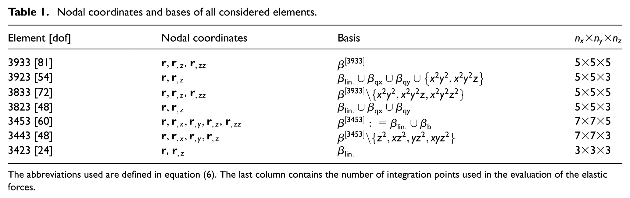
The abbreviations used are defined in equation (6). The last column contains the number of integration points used in the evaluation of the elastic forces.
Two of the elements, namely 3933 and 3923, have nine nodes. Element 3933 is characterized by the fact that it uses an approximation of order 2 in all three directions. Element 3923 employs linear polynomials for the approximation in the z direction. Furthermore, two eight-node elements 3833 and 3823 are examined. They are similar to their nine-node counterparts, but since they lack a middle node, they make use of a basis containing three monomials less than elements 3933 and 3923, respectively.
For comparison, also the three four-node elements 3453, 3443, and 3423 are considered. Again, element 3453, originally proposed in Matikainen et al., 12 uses an approximation of order 2 in the z direction, while element 3443 is linear in the z direction. On the other hand, element 3423, which is purely considered for demonstrative purposes, is linear in all directions.
For eight-node elements, there are, in theory, many different possibilities to choose valid bases in the sense that the matrix
The shape function matrices for all above-mentioned elements can now be calculated using equation (5). The shape functions can be given either in physical coordinates

Illustration of a nine-node plate element in physical and in local element coordinates.
Calculation of the elastic forces
In this paper, all considered elements make use of the St. Venant–Kirchhoff material law which assumes a linear relationship between the Green–Lagrange strain tensor
Numerical experiments
In this section, the above-mentioned plate elements are put to test in various numerical experiments. The goal of this analysis is to gain insight into which elements deliver accurate results while still maintaining acceptable convergence rates. Of special interest are the questions whether the introduction of second-order z-derivatives can alleviate certain locking phenomena and whether omitting in-plane slopes is actually beneficial for calculations involving thin plates. The first two tests that are conducted involve small deformations only. This allows for comparisons with approximative analytical solutions in order to eliminate the possibility of any fundamental flaws in element formulation and implementation. After that, two large-displacement tests are conducted. For these tests, reference results are calculated using finite elements provided by the commercial software ANSYS. The elements involved are the solid element SOLID95 and the beam element BEAM188. SOLID95 is a three-dimensional structural solid element with three nodal degrees of freedom for each of its 20 nodes. In general, this element has multiple reference shapes, but for these calculations, hexahedral elements were applied. BEAM188, on the other hand, is a three-dimensional shear-deformable linear beam element with two nodes and 6 degrees of freedom per node. For the calculations in this study, a four-cell cross-section was used. All numeric calculations involving ANCF elements have been performed using MATLAB.
Cantilevered plate
The first test involves a cantilevered plate of the length

Naturally, since the plate of this experiment has a finite width, one cannot expect a result that is identical to the analytical solution. Nevertheless, the results should still be comparable. In particular, for a finitely wide plate with a non-zero Poisson’s ratio, the displacement in the middle of the free end will be larger than in the free corners of the plate. For this reason, the arithmetic means of the vertical displacements of all nodes at the end edge of the cantilever are calculated. Also, in the interest of a more thorough analysis, the nodal displacements with the smallest and largest absolute values are recorded.
The discretization has been chosen so that, as a first priority, all ANCF plate elements are always square-shaped and, as a second priority, so that the resulting number of degrees of freedom is similar for the different elements. The numeric results are depicted in Table 2.
Numeric results for the cantilevered plate experiment with Poisson’s ratio of

The element mesh and numbers of degrees of freedom used are given in square brackets. The values
As can be seen from the results, for elements 3933, 3833, and 3453, the analytical result is well in the range of the nodal displacements. These elements have in common that they employ a second-order approximation in the z direction. In contrast, all elements that are merely linear in the z direction deliver inaccurate results. However, since elements 3923, 3823, and 3443 still give similar values when compared with each other, it seems that a common phenomenon must be responsible for the fact that they converge to the wrong value. Indeed, when repeating the experiment with Poisson’s ratio set to be equal to zero, also elements 3923, 3823, and 3443 deliver correct results. This can be seen in Table 3.
Numeric results for the cantilevered plate experiment with Poisson’s ratio of

In conclusion, these elements suffer from Poisson locking, and similar to the findings for beam elements in previous studies, approximations of at least second order in all directions seem to be a functional remedy for Poisson locking. 8 The linear element 3423, however, suffers from a variety of severe locking phenomena and hence delivers results with absolute values that are approximately an order of magnitude smaller than the reference value.
Simply supported plate under body load
The second numeric experiment is a square, simply supported plate subjected to a body load as previously studied in Matikainen et al.
12
The plate is of the length and width

for the respective thickness values. The setup is illustrated in Figure 3.
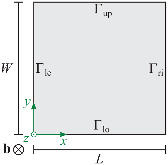
Illustration of the setup for the simply supported plate.
The boundary conditions are given by

The displacements are recorded in the middle of the plate. Once again, there exists a thin-plate analytical solution for this problem. Using Reissner–Mindlin plate theory, 12 this analytical solution of the z displacement in the middle of the plate is of the form

The results are given in Table 4. The reference values given have been obtained by evaluating the sums in equation (9) up to
Results for the center displacements of the simply supported plate under body load for various thickness values.
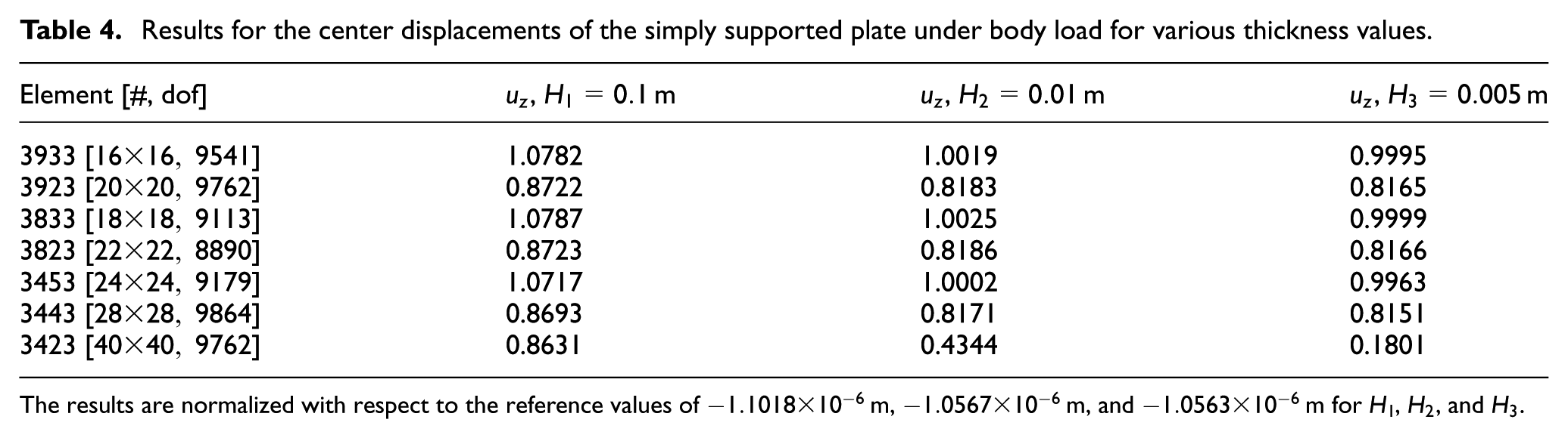
The results are normalized with respect to the reference values of
As can be gathered from the results for all three thickness values, the simply supported plate experiment reinforces the impressions from the previous test. Once more, the elements 3933, 3833, and 3453 deliver correct results. The elements 3923, 3823, 3443, and 3423, on the other hand, are once again incapable of delivering correct displacements. Thus, in the interest of clarity, the remainder of this article will show only results of the three better-performing ANCF elements.
In practical applications, it is not only important that the numerical solution converges to a correct value for increasing numbers of elements, but rather that a satisfactory solution can already be obtained for a modest number of degrees of freedom. Therefore, in the following, the convergence rates for elements 3933, 3833, and 3453 will be investigated. Figure 4(a) and (b) show the relative errors for the thicknesses

In this figure, the relative errors of the displacement results of the simply supported plate under body load are plotted for different numbers of elements. For the calculation of the relative error, the values given in Table 4 were used as the respective reference solutions: (a) H1 = 0.1 m, (b) H2 = 0.01 m, and (c) H3 = 0.005 m.
While for
Even more so, when using exact Gaussian quadrature for all elements, the computation effort per degree of freedom for calculations with element 3453 is larger than for elements 3933 and 3833. The reason for this lies in the fact that the basis used for element 3453 contains monomials up to the third order of x while the other two elements only use monomials up to second order. Hence, for an exact quadrature, element 3453 needs to use more integration points in the x direction.
Furthermore, as demonstrated by Figure 4(c), this locking phenomenon is even more severe for the thinnest considered plate of thickness
However, as the presented results suggest, in the case of ANCF plate elements, it seems that this phenomenon is also connected to the usage of the in-plane slope vectors
Large-displacement cantilever
All previous experiments have dealt with load cases that lead to small displacements. For this reason, the intention of the following experiment is to clarify whether the elements 3933, 3833, and 3453 still deliver reasonable results in the case of large deformations. To this end, a cantilevered plate of the length

Illustration of the setup for the large-displacement cantilever experiment for a total applied force of
For the ANCF elements, the mesh was set up in a way that always one element was used in the y direction while the number of elements in the x direction was increased step by step. The displayed reference result was obtained with the ANSYS solid element SOLID95 and a mesh consisting of 334 elements in the x direction, 100 elements in the y direction, and 1 element in the z direction.
The results of the numerical calculations for different numbers of degrees of freedom are depicted in Figure 6. For all elements, the given displacement value is the arithmetic mean of the vertical displacements of all nodes in the end cross-section.

Results of the large-displacement cantilever test for various elements.
The results show that all of the high-order elements deliver reasonable results. None of the elements shows any sign of noteworthy convergence problems.
Princeton beam experiment
The previous examples have dealt with either small-displacement or simple one-dimensional bending problems. Since the proposed elements are based on full three-dimensional elasticity, they should in theory be usable in a wide range of problems. Hence, in this section, the plate elements are put to the test in the so-called Princeton beam experiment which is a demanding example involving bidirectional bending. First conceived by researchers from Princeton University, 16 this experiment has previously been used to evaluate different beam formulations, including ANCF beam elements. 17
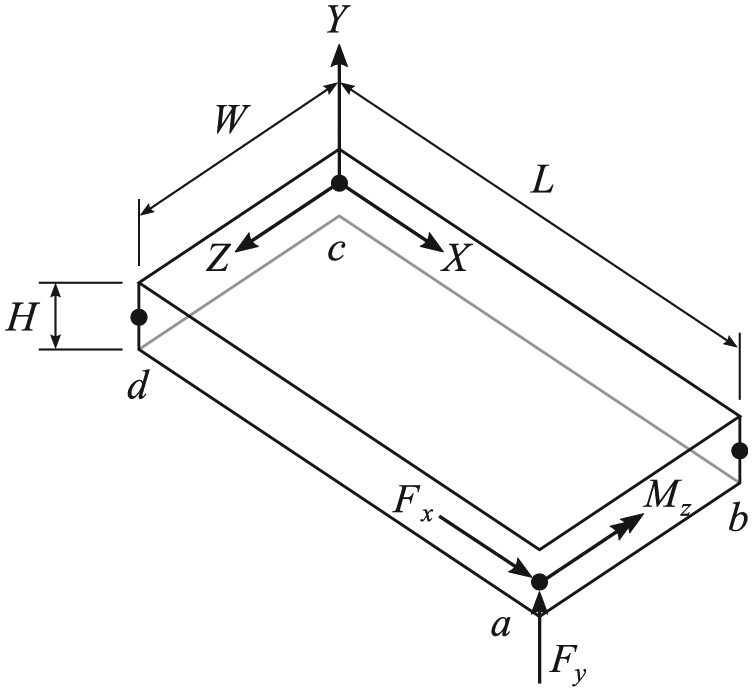
The cantilevered beam is of the length
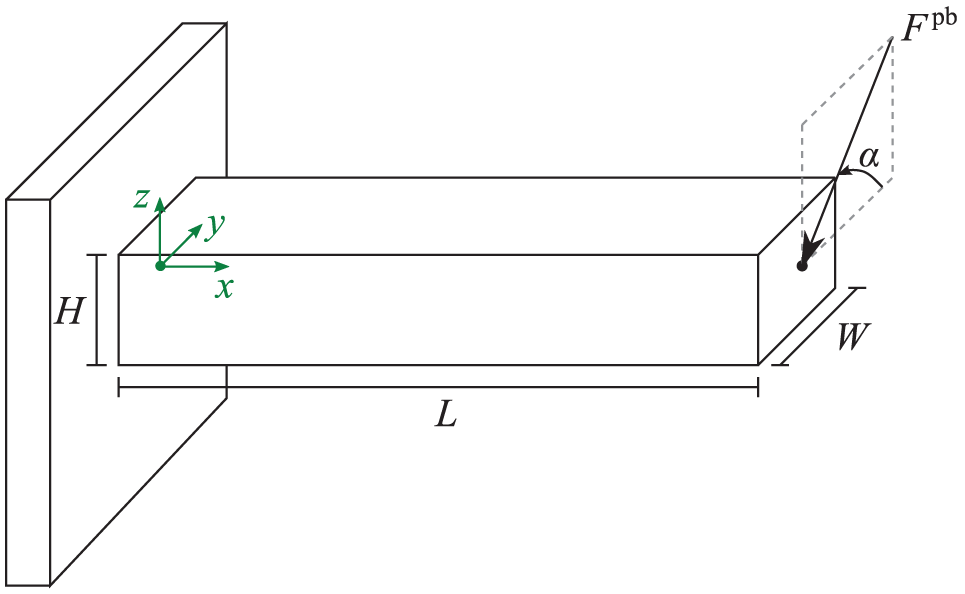
Illustration of the setup for the Princeton beam experiment for a tip load of
For all ANCF elements involved, two elements were used in the y direction so that for all element types, a node exists that is precisely in the middle of the end cross-section. The recorded displacements are those of that middle node. For the elements 3933, 3833, and 3453, respectively, 20, 25, and 40 elements were used in the x direction. As a result, for all three elements, the system has approximately 1800 degrees of freedom. The results for the different load cases are depicted in Figures 8 and 9. For the reference results, 64 elements of the ANSYS beam element BEAM188 and a mesh of
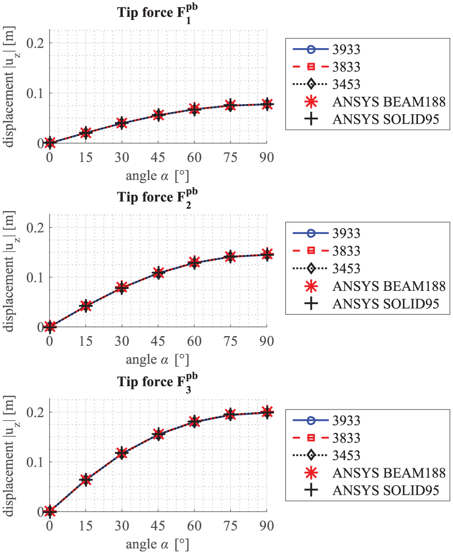
Results for the chordwise displacements in the Princeton beam experiment.
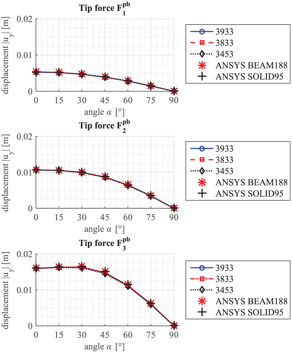
Results for the flapwise displacements in the Princeton beam experiment.
Both the results for the chordwise and flapwise displacements show that all of the elements that have passed the previous tests also deliver reasonable results in all load cases of the Princeton beam experiment. This is of particular significance since the Princeton beam experiment is a rather elaborate test case involving nonlinear effects based on the coupling of axial and transverse normal strains. This becomes manifest in the fact that as the angle
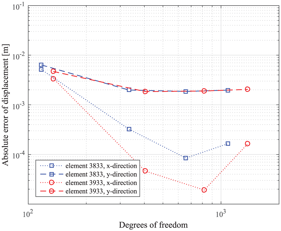
In Figure 10, the y displacements are plotted over different numbers of degrees of freedom. The results have been obtained for the load case with an angle of

Results for the flapwise displacement of the Princeton beam experiment with an angle of
As the results show, the elements 3933 and 3833 actually seem to be able to deliver results that are in better concordance with those obtained with the ANSYS solid element SOLID95. The displacement for element 3453, on the other hand, seems to converge to an absolute value that is slightly smaller.
Dynamic test
The example case selected for the dynamic test is the moderately thick free-flying plate problem presented in Figure 11, originally developed by Matikainen et al.
12
The example was solved using the higher-order ANCF plate elements 3833 and 3933, which have been chosen due to their good performance in the previously presented static examples. The material parameters used in the test are as follows: Young’s modulus is


the loading of the plate varies as a function of time. The total duration of the simulation is 2.5 s. The results are computed using MATLAB’s integrated solver ode15s, which is a variable order integrator for stiff problems, with an output step length of
Free flying flexible plate.
The reference results are calculated using a
The absolute error of the displacement of point a at time
Absolute error of the displacement of point a at

Norm of the displacement error of point a at
Comparison of the computational effort for the simulation over the time interval

DOF: degree of freedom.
“Eval.” denotes the number of function evaluations of the equations of motion and “Time” denotes total computation time, scaled with respect to the smallest value.
While Figure 12 shows a certain degree of difference between the ANSYS model and the higher-order plate element models, particularly in the y-directional displacement, it can be concluded from the simulation that generally the higher-order plate models behave very similarly to the ANSYS model. In particular, the plate’s rotation is reproduced in the proper way without incorrect strains. Predictably, Table 5 shows that the more complex element 3933 is more computationally demanding, while, according to Figures 12 and 13, element 3833 converges to roughly the same error value with fewer degrees of freedom.
Conclusion
This study introduces high-order three-dimensional plate elements based on the ANCF for large deformation multibody applications. The introduced elements employ eight or nine nodes.
Contrary to quadrilateral ANCF plate elements considered in previous studies, the two proposed eight- and nine-node high-order plate elements deliver reasonable results in all considered load cases while exhibiting satisfactory convergence rates. Specifically, both Poisson and shear locking are resolved through the setup of the two elements. In this study, Poisson locking disappears for all elements that have at least an approximation order of two in all directions. In addition, the absence of in-plane slope vectors in the nodal coordinates of the two elements seems to lead to elements that do not suffer from severely deteriorated convergence rates in case of very thin plates.
The considered load cases include two small-displacement tests with one being a cantilevered plate and the other one being a simply supported plate under a uniform body load. For the latter one, an examination of the convergence rates for different thicknesses revealed the advantages of the considered high-order eight- and nine-node elements when compared to the four-node fully parametrized high-order ANCF plate element that has been introduced in previous studies. 12
Furthermore, two large-displacement load cases, namely one large-displacement cantilevered plate in one-dimensional bending and the so-called Princeton beam experiment involving bidirectional bending, have shown that the proposed elements also behave favorably in more elaborate situations. Finally, the two proposed eight- and nine-node elements that behaved well in the static tests have been applied in an exemplary dynamic benchmark test, showing that they are also functional in simulations over the time domain.
Footnotes
Academic Editor: Xiaoting Rui
Declaration of conflicting interests
The author(s) declared no potential conflicts of interest with respect to the research, authorship, and/or publication of this article.
Funding
The author(s) disclosed receipt of the following financial support for the research, authorship, and/or publication of this article: The authors would like to thank the Academy of Finland (Application No. 259543 for the funding of Postdoctoral Researchers and Application No. 285064) for supporting Marko K. Matikainen.