
Abstract
To accurately describe mechanical characteristics in the modeling and analysis of bolted joint structure in complex mechanical system, this article investigates on the equivalent parameters of mechanical characteristics (tension and compression stiffness, bending stiffness, shear stiffness, and torsion stiffness) of bolted joints by theoretical derivation and provides an effective modeling approach with thin-layer element theory and equivalent parameters as well. First, the equivalent parameters of mechanical characteristics of bolted joints are achieved. And then the finite element model of bolted joint is established by equivalent parameters, called as parametric modeling method. Based on two cases of study, the mode analyses of parametric finite element models are implemented with dynamic test data to validate the developed parametric finite element models of bolted joints with the equivalent parameters. It is shown from the investigations that parametric finite element models have higher precision than finite element model in structural dynamic analysis because the analytical results based on parametric finite element models are closer to test data. It is fully demonstrated that the equivalent parameters may effectively simulate the mechanical characteristics of bolted joint structures, and the parametric modeling approach with equivalent parameters is efficient and high fidelity for bolted joints in complex machinery due to high precision in mode analysis. The efforts provide an effective modeling method for simulating the mechanical characteristics of bolted joints and designing bolted joint structure in complex machinery.
Keywords
Introduction
As an important connection of components in complex machinery, bolted joint has many advantages, such as simple manufacturing, convenient assembly, large bearing capacity and high reliability, and so on. Currently, bolted joint has been widely applied in many engineering fields such as spacecraft, aircraft, ship, automobile, weapon, and so forth.1–3 Under the external static/dynamic loads, the variation of bolted joint statuses (for instance, looseness, slippage, and fracture) directly influences the security, reliability, and dynamic performance of structural or mechanical system. 4 Bolted joints are always used to connect components and transfer force and moment of force, which largely affect vibration performance, reliability, and dynamic performance of integral structure in complex mechanical system. 5 Therefore, how to accurately and effectively simulate the mechanical characteristics of bolted joints is a key issue in the modeling of high fidelity finite element (FE) model (FEM) of mechanical structures.
Model is an approach to access engineering from mechanics. Recently, many efforts have been done for the modeling issue of bolted joint structure. Hanss et al. 6 and Ahmadian and Jalali 7 adopted spring element to equivalently simulate the property of bolted joints. Song et al., 8 developed the beam element simulation method of bolted joint. Ahmadian et al. 9 built the FEM based on thin-layer element method. Kim et al., 10 Sharma and Desai, 11 and He and Zhu, 12 focused on the refined FE modeling method for bolted joint structures. Zhai et al.,13–16 investigated on the simulation of mechanical features of bolted joints based on FE modeling. Actually, the above modeling methods include non-parametric modeling approach and parametric modeling approach. 17 Hereinto, parametric modeling approach is employed to acquire the equivalent parameters of bolted joint structure in line with the physical phenomenon and microcosmic mechanism of linkage structures. And then the real characteristics of bolted joint structures are simulated. Obvious advantages on parametric modeling approach are that the complex characteristics of structures can be equivalently simulated by simple structural form and a small number of parameters. As a consequence, parametric modeling approach is quickly developing. For parametric modeling, a large number of works are also done with the emphasis on single mechanical characteristic of bolted joints. For instances, Alkatan et al. 18 discussed the axial stiffness of bolted joints; Chakhari et al. 19 investigated the tension and compression stiffness of bolted joints; Hoang et al. 5 focused on tension stiffness and shear stiffness of bolted joints. However, bolted joint has stiffness on seven directions. By considering periodicity, it is necessary to simulate five stiffness including tension and compression stiffness, bending stiffness, shear stiffness, and torsion stiffness. Most of the studies only considered one or two stiffness of bolted joints in parametric modeling for specific engineering structure. A complete parametric modeling theory and method are still not developed for the equivalent simulation of difference stiffness of bolted joint structure from mechanics.
The purpose of this article is to derive the mechanical characteristics of bolted joint structure and then develop a whole parametric modeling technology based on thin-layer element and FE methods. Two engineering cases are investigated to test the effectiveness and accuracy of the developed parametric modeling method based on dynamic testing data of vibration modes. This parametric modeling approach is applied in the modal analysis of the casings of turbofan engine by the mechanical characteristics simulation of bolted joints. And then the parametric modeling method is validated to be efficient in the parametric modeling of large-scale complicated structures.
In what follows, in section “Parametric modeling theory,” parametric modeling theory is introduced based on thin-layer element method. Section “Equivalent parameters of mechanical characters on bolted joint structure” derives the equivalent parameters of five stiffness of bolted joint structures detailedly. The parametric model of complex structures with bolted joint is established based on thin-layer element theory and equivalent parameters and is validated by two examples in section “Study examples.” Section “Conclusion” gives some conclusions on this investigation.
Parametric modeling theory
Based on thin-layer element theory, the parametric modeling method of bolted joint structure is discussed in this section. According to parametric modeling method, an effective model is established by equivalent parameters substituting for the mechanical characteristics of structures. 14 In line with the thin-layer element, the process of parametric modeling of bolted joint with FE method is shown in Figure 1. In the parametric finite element model (PFEM), hexahedron element with eight node and Cartesian coordinate is chosen.

FE model forming process of bolted joint structure.
The relationship among the displacements of nodes in hexahedron element is
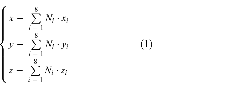
where Ni is the shape function of isoperimetric element of hexahedron, and (xi, yi, zi) is the coordinate of the ith node.
Based on elastic characteristics, the relationship between element strain and node displacement is denoted by

where

where
When the coupling among stiffness in all directions is ignored, for the interface of bolted joint structure, the elastic matrix
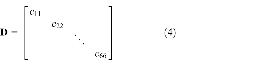
where c11, c22, and c33 are the elasticity modules on three direction, respectively, and c44, c55, and c66 are the shear modules on three direction, respectively.
According to virtual work principle, the element stiffness matrix

where i, j = 1, 2, …, 8 represent the number of node.
In equation (5), there are

Finally, stiffness matrix

where i, j = 1, 2, …, 8; k ≤ 8 is the node number of element;
In equation (7), structural stiffness matrix
Equivalent parameters of mechanical characters on bolted joint structure
In this section, the equivalent parameters of five different stiffness (tensile stiffness, compressive stiffness, transverse bending stiffness, shear stiffness, and torque stiffness) are derived based on thin-layer element theory.
Tension and compression stiffness
According to the Hoang et al., 5 the tension and compression stiffness of bolted joints are

where FN is the axial force, and Δl is the axial displacement caused by the axial force FN.
When the axial displacement xi and force Fjx on node ai are the axial displacement and force of whole bolted joints, respectively, we input the boundary conditions and load into equation (7) and gain the jth force

where [
By resolving equation (9), the axial stiffness is achieved as

When the thickness of thin-layer element is far smaller than the sizes of other two directions, there is

Inputting shape function Ni into equation (11), there is
For bolted joint structure suffering from the axial force, the lateral displacement is almost 0, that is

Importing equations (12) and (13) into equation (10), the axial stiffness is rewritten as

In equation (14), first two terms denote thin-layer elements, while the rest terms indicate the non-thin-layer elements. Obviously, the axial stiffness kN of bolted joint structure is defined by material axial elastic modulus, element shape function, and coordinate displacement. For a certain component, the section size, FE type, and tension–compress stiffness only are related to material axial elastic modulus. Therefore, it is reasonable to ignore the nonlinear stiffness of bolted joint structure and thereby adopt the axial elastic modulus of thin-layer element to simulate the tension–compress stiffness kN when the material property of non-thin-layer element is indeclinable.
Bending stiffness
When bolted joint suffers from horizontal load, the equivalent bending stiffness of bolted joint represented is

where nCT is the ratio of tension stiffness k+ to compression stiffness k−, and b is the diameter of bolted joint.
As shown in equation (15), the bending stiffness kM of bolted joints is related to the tension stiffness k+, compression stiffness k−, and section size. When the section size of thin-layer element is specific and the nonlinear stiffness of tension and compression is ignored (i.e. nCT = 1), the bending stiffness kM is only determined by the axial elastic modulus of thin-layer element.
Torsional stiffness
The torsional stiffness of bolted joint structure is defined by

where T is the torque, Δl is the circumferential displacement of whole structure caused by torque loads, and R the radius of bolted joint.
When node ai and whole bolted joint structure have the same circumferential displacement yi and torque Tjy under torque load, the FE equation (7) is reshaped as follows

where [Kji]
2
(i = 1, 2, …, n) represents the second line of matrix
By solving equation (17), we obtain the torsional stiffness as follows

Similarly

When bolted joint suffers from the torque load, the axial displacement and radial displacement are as follows

By importing equations (19) and (20) into equation (18), the torsional stiffness is simplified as

In equation (21), the first two items belong to thin-layer elements, while the surplus items are non-thin-layer elements. As shown in equation (21), the torsional stiffness of bolted joints is related to circumferential shear modulus, structural size, element shape function, and coordinate displacement. For a specific component, torsional stiffness is only related to the circumferential shear modulus of material. Therefore, the torsional stiffness kθ is defined by the circumferential shear modulus of thin-layer elements.
Shear stiffness
The shear stiffness of bolted joint is defined by

where FS is lateral shear force, and Δl is the transverse displacement of contact surface effected by lateral shear force FS.
When the displacement zi and load Fjz of node ai on z direction are the transverse displacement due to lateral shear force and the shear force of the contact surface bolted joint, by solving FE equation (7), there is

where [Kji]
3
(i = 1, 2, …, n) represents the third line of matrix
Resolving equation (23), the shear stiffness on z direction is rewritten as
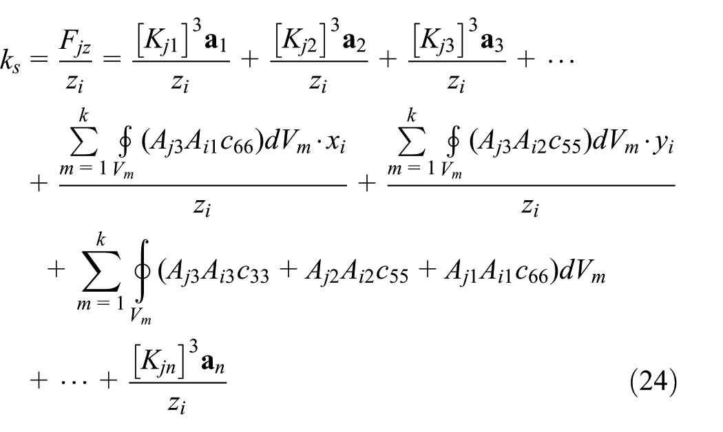
Similarly

Inputting equation (25) into equation (24), the shear stiffness on z direction is simplified as

When the load Fjy and displacement yi on node aj on y direction represent the horizontal shear force of whole structure and the displacement effected by the horizontal shear force, the shear stiffness on y direction is as follows

The first two items of equations (26) and (27) represent thin-layer elements, while others denote non-thin-layer elements. The shear stiffness of bolted joint is linked with tangential shear modulus, element shape function, and coordinate displacement. For a specific component, the shear stiffness is only related to the tangential shear modulus of materials. In equations (26) and (27), c44 and c66 are the shear stiffness of structure on y and z direction, respectively. Therefore, the shear stiffness is defined by the tangential shear modulus of thin-layer elements as material properties are invariable.
The equivalent parameters of five stiffness of bolted joint are derived based on thin-layer element, which is beneficial to the parameterized simulation and modeling on the mechanical characteristics of bolted joints. From the above analysis, it is acquired that bending stiffness kM, tension stiffness kN+, and compression stiffness kN− of bolted joint structure are determined by the axial elastic modulus of thin-layer elements when the nonlinearity of tension and compression stiffness is ignored. Nevertheless, torsional stiffness kθ and shear stiffness ks of bolted joint structure are determined by circumferential shear modulus and tangential shear modulus of thin-layer elements, respectively, when the parameters of material property of non-thin-layer elements are constant.
Study examples
In this section, the bolted joint structure with flanged mounting edge and thin-walled cylinder with bolted joint are selected as the objects of study to validate the proposed parametric modeling approach. First, PFEMs are structured by simulating bolted joint structure based on the equivalent parameters of mechanical characteristics and thin-layer element theory. And then the effectiveness and accuracy of the parametric modeling method are evaluated by the comparison of dynamic mode analyses with dynamic testing data and FE analysis. Herein, the rationality of the equivalent parameters of mechanical properties of bolted joints from theoretical derivation is validated by the accuracy of PFEM established in the two cases.
Case 1
The flanged mounting structure with bolted joint is shown in Figure 2. Herein, the same length, width, and thickness for beam 1 and beam 2 are 200, 40, and 10 mm, respectively. The mounting height of bolted joint is 40 mm. One end of beam 1 is fixed and the other is connected with beam 2 by three bolts as an integral structure.

Sketch map of flanged mounting structure with bolted joint.
Based on the parametric modeling approach with thin-layer element, the process of parametric FEM is shown in Figure 3. Two beam structures and thin-layer component are generated by Solid 186 in ANSYS software. Beam structures and thin-layer component are rigidly connected by the common nodes. With equations (14), (15), (21), (26), and (27), the stiffness features of bolted joint are simulated under the pretightening force 4 N m by thin-layer element. The boundary conditions are indicated in Figure 3. The part with the length 70 mm from the fixed end of beam 1 is fully constrained which is consistent with the experiments. For the developed PFEM in this article and coupling model (FEM with integration of rigid on beam 1 and beam 2), the analytical results are listed in Table 1. Herein, the elasticity modules of PFEM and FEM are 1.93 and 2.11 GPa, respectively.
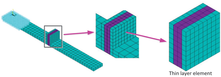
Parametric finite element model of bolted joint structure.
Comparison of analytical and experiential results on natural frequencies for case 1 (unit: Hz).

FEM: finite element model; PFEM: parametric finite element model.
In this experiment, the vibration test and analysis system (mode no. LMS SCADAS III) and the corresponding Test Lab software are adopted to monitor the vibration modes of bolted joint structure. The experimental measurement system and test piece are illustrated in Figure 4. Based on this experiment, first five natural frequencies of bolted joint structure are acquired in Table 1 under the effect of 4 N m tightening torque. First five vibration modes are located in Figure 5. The data of first five natural frequencies of bolted joint structure from PFEM, FEM, and testing are compared in Table 1 and Figure 6.

(a) Test measurement system of vibration modes and (b) test piece.

First five order modes of vibration on flanged mounting structure with bolted joint.

Comparison of analytical results and experimental data for case 1.
Case 2
The investigation on case 1 verifies the validity of the equivalent simulation on mechanical characteristics of bolted joint structure by the presented parametric modeling technique with thin-layer element and equivalent parameters. To further support the applicability of this parametric modeling method, a complex structure, thin-wall casing with bolted joints shown in Figure 7, is selected to investigate the corresponding experiment and the parametric FE modeling and simulation. In Figure 7, the model comprises two same thin-walled cylinder structures. The two structures are connected by the standard bolts with M20. The parameters of thin-walled cylinder structure with bolted joints are listed in Table 2.

Thin-walled cylinder structure with bolted joints.
Parameters of thin-walled cylinder structure with bolted joints.

Similarly, FE analysis software (ANSYS) was adopted to build the PFEM of bolted joints by solid element (Solid 186). The process of parametric modeling for thin-walled cylinder structure with bolted joints is drawn in Figure 8. The material property of thin-layer elements is defined. The stiffness properties of bolted joints were simulated under the effect of 100 N m pretightening force by equivalent parameters and thin-layer element. Then, the modal analysis of thin-walled cylinder structure with bolted joints was performed based on PFEM. The first four modes of vibration were compared with these of rigid integration modeling method and experiment. The results on first four nature frequencies for test data, PFEM, and FEM are shown in Table 3 and Figure 9. Hereinto, the elasticity modules of PFEM and FEM are 1.88 and 2.1 GPa, respectively. The test measurement system and test piece are shown in Figure 10. The first four modes of vibration in analytical results are shown in Figure 11. In this experiment, dynamic modes of thin-walled cylinder structure with bolted joints are measured by vibration mode testing system. The boundary conditions on this experiment are consistent with the corresponding FEM analysis. The thin-walled cylinder structure with bolted joints is fixed on trestle table by an elastic rope.
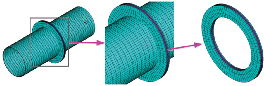
Process of parametric finite element modeling for thin-walled cylinder structure with bolted joints.
Comparison of analytical (PFEM and FEM) and experiential results on natural frequencies for case 1 (unit: Hz).

FEM: finite element model; PFEM: parametric finite element model.
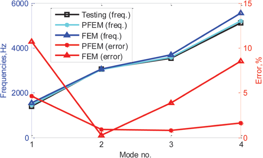
Comparison of analytical results and experimental data for case 2.

(a) Test measurement system and (b) test piece.

First four order modes of vibration for thin-walled cylinder structure with bolted joints.
Discussion
In the light of the analyses and validation of the above two cases, some results can be uncovered as follows.
As illustrated in Figure 6, the curve of frequency on PFEM is almost coincident with testing curve, while the curve of frequency on FEM has a large deviation from testing curve, and thus, the error curve of PFEM is far lower than FEM. Simultaneously, as shown in Table 1, the error of natural frequencies between parametric model (PFEM) and testing is very small, less than 3%, and the mean error is only 1.304%, which is far less than the coupling model (FEM) with the maximum error 19.2% and the mean error 12.66%. Relative to the coupling model, the precision of natural frequencies from PFEM gets a large improvement by 5.6%–18.6% and the average improved accuracy is 11.356%. It is revealed in Table 1 and Figure 6 that (1) the stiffness of bolted joint markedly influences the simulation and design of integral structure; (2) the stiffness characteristics of bolted joint can be effectively simulated equivalently by the proposed parametric modeling technique with thin-layer element method and equivalent parameters; and (3) the FEM without equivalent parameters is inefficient to reflect the mechanical characteristics of bolted joint structure and thereby generates large error of modeling.
By the same token, it is illustrated in Figure 9 that (1) the frequency curve of PFEM is also almost superposed with testing curve; (2) the frequency curve of FEM has a large deviation from testing curve, especially on the fourth order mode of vibration; and (3) the error curve of PFEM is much lower than FEM. It is demonstrated in Table 3 that (1) for PFEM, the maximum error, minimum error, and mean error between analytical results and testing data are 4.6%, 0.8%, and 1.975%, which far less than the maximum error 10.7% and the mean error 5.83% for the coupling model without equivalent parameters; (2) the mean accuracy of natural frequencies for the developed PFEM with equivalent parameters is improved by 3.855% from 5.83% to 1.975% relative to FEM analysis. The nature frequencies of thin-walled cylinder structure with bolted joints based on the presented PFEM are almost consistent with these from the testing. Therefore, the parametric modeling approach with thin-layer element and equivalent parameter can effectively simulate the stiffness characteristics of complex thin-walled cylinder structure with bolted joints forced by preload.
In brief, the presented parametric modeling theory and method with thin-layer element and equivalent parameter is efficient and high fidelity in simulating the mechanical characteristics of bolted joint structures. It is effective and reasonable to adopt the derived equivalent parameters to establish the model of bolted joint instead of the mechanical characteristics of bolted joint structure.
Conclusion
The objective of this study is to investigate on the equivalent parameters of mechanic characteristics (stiffness) of bolted joint structure based on thin-layer element theory and validate the feasibility and availability of the equivalent parameters in the parametric modeling of complex structures with bolted joints. The dynamic modes of vibration for complex structures with bolted joints are investigated by two cases. Some efforts and conclusions are summarized as follows:
Five stiffness of bolted joint are derived based on thin-layer element theory and the equivalent parameters of mechanical characteristics (five stiffness) of bolted joint structure. It is acquired that (1) bending stiffness kM, tension stiffness kN+, and compression stiffness kN− of bolted joint structure are quantified by the axial elastic modulus of thin-layer elements when the nonlinearity of tension and compression stiffness is ignored; (2) torsional stiffness kθ and shear stiffness ks of bolted joint structure are determined by circumferential shear modulus and tangential shear modulus of thin-layer elements, respectively, when the parameters of material property of non-thin-layer elements are constant.
The stiffness of bolted joint seriously influences the simulation and design of integral structure with bolted joints and thus should be considered in the modeling of bolted joint structures.
For bolted joints, the parametric model established by thin-layer element theory and equivalent parameters holds high precision and high fidelity for the mechanical features simulation of bolted joint structure.
The efforts of this article provide an effective reducing and modeling technique for the simulation and design of the mechanical characteristics of bolted joints in complex machinery.
Footnotes
Academic Editor: Yangmin Li
Author note
Author Zhi Wang is also affiliated to College of Aerospace Engineering, Shenyang Aerospace University, Shenyang, China.
Declaration of conflicting interests
The author(s) declared no potential conflicts of interest with respect to the research, authorship, and/or publication of this article.
Funding
The author(s) disclosed receipt of the following financial support for the research, authorship, and/or publication of this article: This paper is co-supported by National Natural Science Foundation of China (Grant No. 51605016), the Funding of Hong Kong Scholars Program (Grant Nos. XJ2015002 and G-YZ90), and China’s Postdoctoral Science Foundation (Grant No. 2015M580037).