
Abstract
A kind of flux-weakening control method based on speed loop structure-variable sliding mode controller is proposed for interior permanent magnet synchronous motor in electric vehicles. The method combines maximum torque per ampere with vector control strategy to control electric vehicle’s interior permanent magnet synchronous motor. During the flux-weakening control phase, the anti-windup integral controller is introduced into the current loop to prevent the current regulator from entering the saturated state. At the same time, in order to further improve the utilization rate of the direct current bus voltage and expand the flux-weakening regulating range, a space vector pulse-width modulation over-modulation unit is employed to contravariant the direct current bus voltage. Comparing with the conventional proportional–integral controller, the proposed sliding mode control algorithm shows that it has more reliable control performance. In addition, more prominent flux-weakening performance of the proposed flux-weakening method is illustrated by numerical simulation comparison.
Keywords
Introduction
Recently, the interior permanent magnet synchronous motor (IPMSM) has been widely used in high-performance applications due to its advantages, such as small volume, high efficiency, as well as high power density.1,2 In the electric vehicle driving system, the motor speed should closely follow a specified reference trajectory, regardless of any load disturbance, parameter variation, and model uncertainty. Additionally, a wide speed range covers the constant torque, and the constant power region is desired.
For electric vehicles, there exist inevitable interferences such as current coupling, friction force, parameter variation, as well as load disturbance during the running process. Due to the presence of these interferences, it is difficult to describe IPMSM with accurate mathematical model, and it is hard to quickly suppress these disturbances with a linear control method. Structure-variable sliding mode control is a kind of nonlinear control method which could self-adjust in accordance with the current state of the system. It does not require accurate mathematical model and can purposefully force the system to move according to the scheduled sliding mode trajectory. The sliding mode trajectory can be set artificially in advance, and it is irrelevant to the object parameters and disturbances.
When IPMSM runs below the base speed, the maximum torque per ampere3,4(MTPA) is commonly used for constant torque control. The MTPA is often implemented using look-up table method or curve fitting method. With poor real-time performance, and high memory cell consumption,
5
the look-up table method has lower industrial popularity. The curve fitting algorithm is often used in engineering practice instead. In Dominguez
6
and Huang et al.,
7
the curve fitting algorithm is adopted to decompose the relationship among the quadrature-axis current, direct-axis current, and electromagnetic torque. The relationship between the quadrature-axis current
When IPMSM runs above the base speed, the flux-weakening (FW) algorithm is usually employed to implement constant power control. Common methods for FW control strategy include formulation calculation method,
9
gradient descent algorithm,
10
look-up table method,
11
and negative
Based on the existing research results, a kind of FW control system combined with the rotor field-oriented vector control algorithm is proposed in this article. The combination of the MTPA algorithm and the FW algorithm improves the performance and efficiency of the electric vehicles by regulating the current of the motor in the whole running process. To consider the constraint of the battery capacity of the electric vehicles and to improve the utilization rate of the direct current (DC) bus voltage of the inverter, a kind of space vector pulse-width modulation (SVPWM) over-modulation method is adopted. Meanwhile, a kind of feed-forward compensation method is introduced to realize the decoupling control and then improve the dynamic response of the current regulator. In order to depress motor’s internal and external interferences, and to achieve faster response, stronger adaptability, and higher control precision, a kind of SMC is designed to replace common proportional–integral (PI) controller. To prevent the voltage saturation of current controller, a kind of anti-windup integral controller is employed to improve the dynamic performance of the loop.
Model of IPMSM
The mathematical model of IPMSM in the d-q synchronously rotating reference frame can be obtained from the three-phase synchronous machine model. Due to the constant field produced by permanent magnets, the field variation is zero, and the following are assumed:
Saturation and losses of the core are negligible.
The induced electromotive force (EMF) is sinusoidal.
There is no dampener winding on the rotor.
Under these assumptions, the voltage and electromagnetic torque equations are

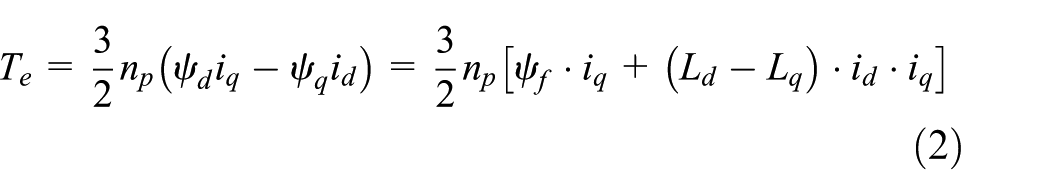
In which,
The torque balance expression of the three-phase IPMSM is presented as follows
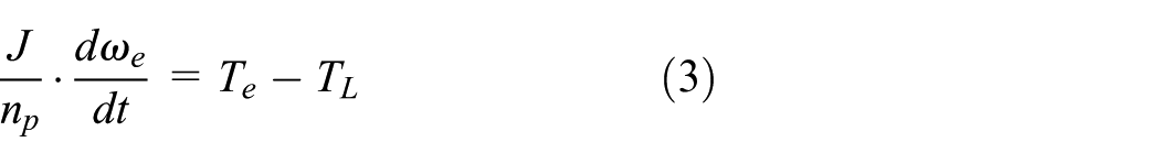
where J is the rotational inertia,
The design of the SMC
Assuming that the speed error is e,

where

The sliding mode surface is designed as

According to the Lyapunov’s stability criterion, when V is positive definite and it has the continuous first-order partial derivative, as well as its first-order partial derivative is negative semi-definite, then the system is stable. In order to ensure

Combining equations (5) and (6) yields the following

The above analysis shows that the designed control law can guarantee that the system gets to the sliding mode surface gradually and steadily. The design of the SMC is depicted in Figure 1.

The design of SMC controller.
Constant torque control strategy
Using vector control method, the running regions of IPMSM include constant torque area and constant power area. The most common control strategy for constant torque area is MTPA, which can reduce the input current and cut the switching loss of the inverter by coordinating torque with current and meanwhile satisfy the required torque output. Thus, the MTPA algorithm is more suitable for IPMSM than other traditional method. Setting

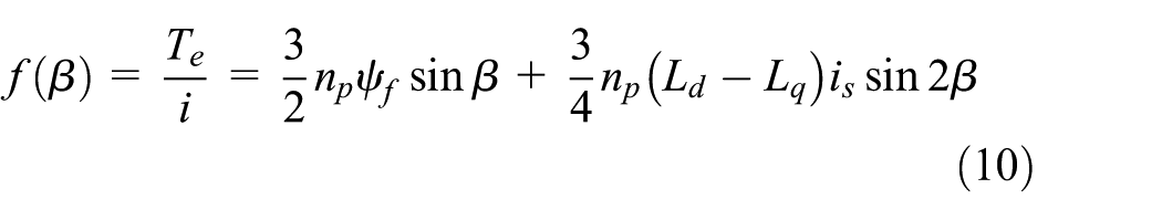
Substituting formula (8) into formula (2) yields the following
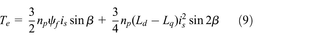
According to formula (9), the relationship between the unit current electromagnetic torque and the current phase angle
The amplitude of
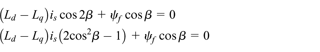
From the formula above, we have

Substituting the formula above into formula (8), yields
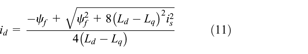
Substituting the relationship

If equation (12) is substituted into formula (2), then
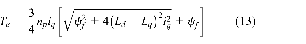
If

Use equations (12) and (14) to build simulation model. The simulation design of MTPA is shown in Figure 2.
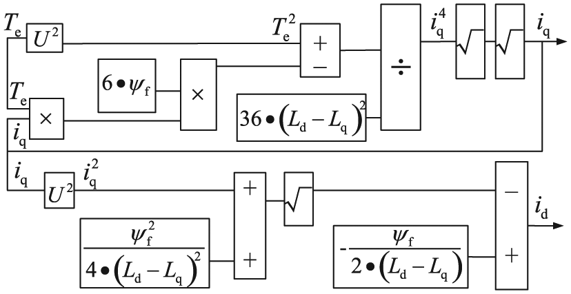
The design of MTPA.
Constant power control strategy
The design of the FW system
The armature voltage of the motor cannot exceed its rated value, and the internal back electromotive force (BEMF) must be lower than the rated value. The BEMF is proportional to the product of the air-gap flux and the speed, and then, to raise the speed, the air-gap flux must be reduced. When an IPMSM is fed by an inverter, the armature current and voltage may not exceed the maximum inverter current and the voltage. These constraints can be expressed as
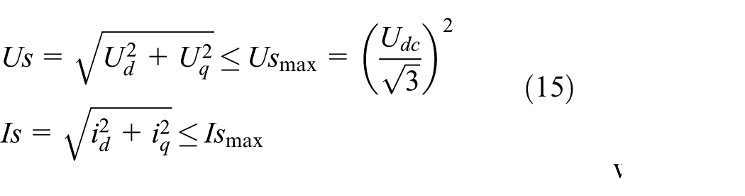
where
The relationship table.
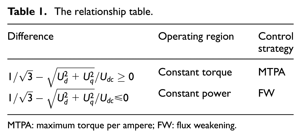
MTPA: maximum torque per ampere; FW: flux weakening.
Neglecting the armature resistance component in equation (1), the steady-state voltage equation can be expressed as

Substituting equation (16) into equation (15) yields

From equation (17), it is obvious that when the terminal voltage value Us has reached its upper limit value
Figure 3 shows the principle of the FW control.

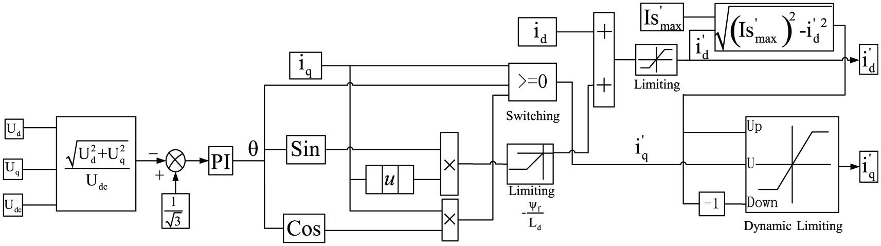
The FW module schematic.
By this way, we get the d-q axis current
Meanwhile, in order to ensure

where the
The anti-windup integral controller
In this article, the back calculation and tracking (BCT) method is employed to compensate the integral windup. Figure 4 is the block diagram of the BCT scheme, where

The block diagram of the anti-windup integral scheme.
The d-q axis current decoupling
From the equation (1), we have
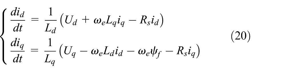
It is obvious that the d-q axis currents
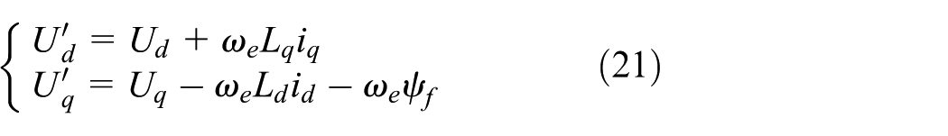
where
Substituting equation (21) into equation (20), we have

By this way, the d-q axis current cross-coupling is eliminated in equation (22) and Figure 5.

The design of d-q axis current decoupling unit.
The SVPWM over-modulation unit
Comparing with sinusoidal pulse-width modulation (SPWM) method, SVPWM can degrade the switching loss and prevent the current distortion; therefore, it is widely used. But traditional SVPWM modulation method only has finite utilization rate of the inverter DC bus voltage, and it narrows the running region and degrades control performance of the motor. Considering the limit of the battery capacity, a kind of SVPWM over-modulation method is adopted to further improve the utilization rate of the inverter DC bus voltage.
Over-modulation has two parts: over-modulation I zone and over-modulation II zone. As shown in Figure 6(a), in over-modulation I zone, reference voltage vector
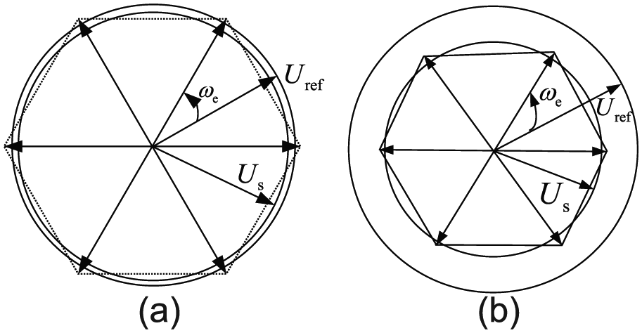
(a) Over-modulation I zone and (b) over-modulation II zone.
In the first sector, for example, as shown in Figure 7,

Over-modulation principle diagram.
When

or

When over-modulation occurs, we should recalculate the action time of

When

Flowchart of over-modulation implementation.
The principle diagram of the FW control system
The complete control scheme of the proposed FW system in this article is presented in Figure 9. The electromagnetic torque

The FW control schematic.
The simulation analysis
Parameters in the simulation model are presented in Table 2.
The simulation parameters.

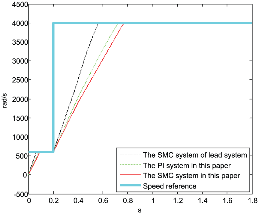
To verify the performance of the proposed FW control system, several simulation tests are implemented under different operating conditions. Figures 10–12 represent the output value of the speed, the torque, and the angle of the SMC system, respectively, in this article and the SMC system of traditional lead angle at the speed from 600 to 4000 rad/s.
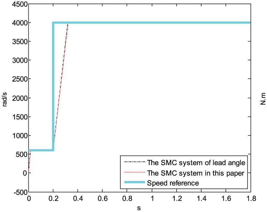
The speed reference and measured value at 4000 rad/s.

The electromagnetic torque output value at 4000 rad/s.
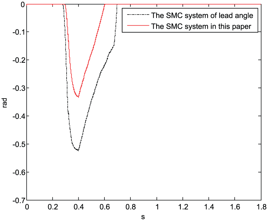
The FW angle output value at 4000 rad/s.
Figures 13–15 denote the output value of the speed, the torque, and the angle of the SMC system, respectively, in this article without the anti-windup integral controller and the over-modulation unit at the speed from 600 to 4000 rad/s.

The speed reference and measured value at 4000 rad/s without the anti-windup integral controller.
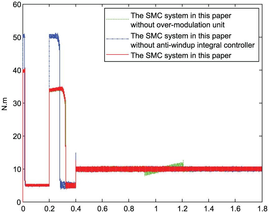
The electromagnetic torque output value at 4000 rad/s without the anti-windup integral controller.

The FW angle output value at 4000 rad/s without the anti-windup integral controller.
Under the same operating conditions, the more negative angle system describes that the more the system’s terminal voltage exceeds the maximum voltage, the deeper the FW level. This indicates that the system has lower utilization to DC bus voltage and has worse FW performance.
As seen from Figures 10 to 12, under almost the same speed and torque respond, the absolute value of FW angle output of the SMC system in this article is smaller than that of the SMC system of traditional lead angle. The comparison demonstrates the effectiveness of the FW method in this article.
As shown from Figures 13 to 15, if the original system does not have the anti-windup integral controller, the absolute value of FW angle output will obviously become larger. Meanwhile, when the motor starts at 0 s and accelerates at 0.2 s, the system will output a bigger torque because the current regulator has entered the saturated state at these moments.
In addition, if the original system does not have the over-modulation unit, the system will yield a bigger absolute value of FW angle. Besides, its speed and torque respond will begin to fluctuate.
The experiments mentioned above have illustrated that the anti-windup integral controller and the over-modulation unit are necessary and helpful to improve the IPMSM FW performance. The ability to track signals precisely and instantaneously is necessary for motor control. For this purpose, the speed reference is suddenly decreased from 600 to −4000 rad/s at 0.2 s in Figures 16 and 17.

The speed reference and measured value at −4000 rad/s.
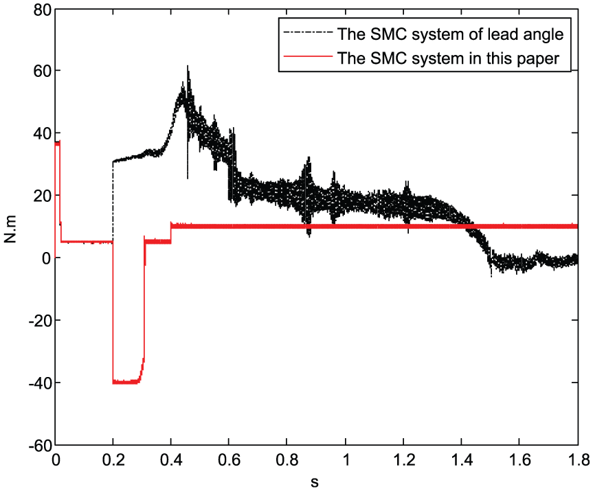
The electromagnetic torque output value at −4000 rad/s.
When a reverse speed reference signal leads to a reverse current, the SMC system of traditional lead angle becomes out of control. On the contrary, during the process when the speed forward accelerates from 0 to 600 rad/s and then reverses braking into 0 rad/s and again up to −4000 rad/s, the SMC system in this article can always run steadily. The results prove that the FW method in this article has more significant ability to regulate a negative current.
The ability to withstand disturbances is an important feature for IPMSM drive. For this purpose, the load torque

The speed reference and measured value from 30 to −30 N m.

The electromagnetic torque output value from 30 to −30 N m.
As shown above, when a violent fluctuation of the load torque causes rapid current changes, the SMC system of lead angle becomes out of control. The measured speed and torque value of the proposed SMC system can always follow their reference value more smoothly and steadily than the PI system in this article. The results illustrate the validity of the proposed FW method and the SMC algorithm.
The ability to withstand the motor parameter variations is another important criterion of a control system. Experiments have been done in cases when the viscous damping coefficient F raises from 0 to 0.02 N m s in Figures 20 and 21, and the rotational inertia J increases from 1e − 2 to 6e − 2 kg m2 in Figures 22 and 23.

The speed reference and measured value from 0 to 0.02 N ms.

The electromagnetic torque output value from 0 to 0.02 N ms.
The speed reference and measured value from 1e−2 to 6e−2 kg m2.

The electromagnetic torque output value from 1e−2 to 6 e−2 kg m2.
As shown above, with the increase in the friction and the rotational inertia, although other systems have tuned to give an optimum speed and torque respond, the SMC system in this article yields the most significant robust performance with smoother and smaller torque output. It manifests that the SMC algorithm and the FW method in this article contribute to enhance the system control performance.
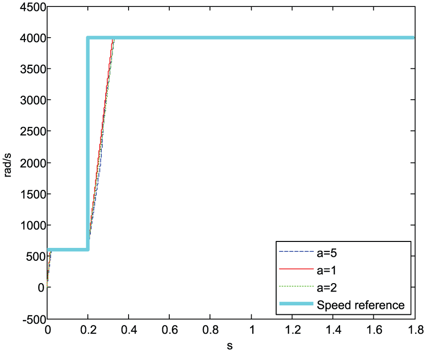
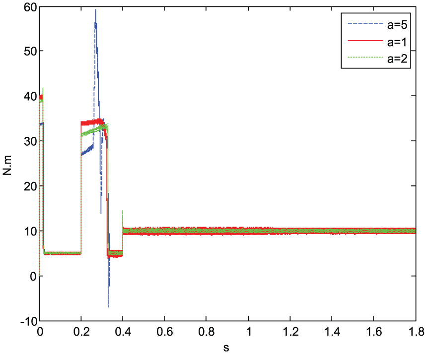
When IPMSM runs above the base speed during FW control phase, the fluctuation of load torque and inductance parameters will influence the system stability and the FW properties. The relevant experiments have been shown in Figures 24–29.

The speed reference and measured value under different load torque reference at 4000 rad/s.

The electromagnetic torque output value under different load torque reference at 4000 rad/s.
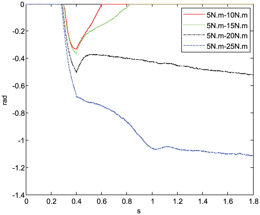
The FW angle output value under different load torque reference at 4000 rad/s.
The speed reference and measured value under different inductance parameters at 4000 rad/s.
The electromagnetic torque output value under different inductance parameters at 4000 rad/s.

The FW angle output value under different inductance parameters at 4000 rad/s.
Figures 24–26 represent the output value of the speed, the torque, and the angle of the SMC system, respectively, in this article under different load torque reference at the speed from 600 to 4000 rad/s. As shown in Figures 24–26, under the same operating conditions, the larger load torque reference results in the larger electromagnetic torque output value and the more negative FW angle. Furthermore, the more negative FW angle further indicates the deeper FW level and the worse FW performance. The simulation results illustrate that with the increase in the load torque reference, the system can be kept stable to a certain extent. But when the maximum load torque reference is increased to 25 N m, the response of speed, electromagnetic torque, and angle begin to deteriorate, and if the maximum load torque reference is larger, the system will tend to be out of control. In this case, we can increase the DC bus voltage
Figures 27–29 represent the output value of the speed, the torque, and the angle of the SMC system, respectively, in this article under different inductance parameters at the speed from 600 to 4000 rad/s.
Considering that the inductance parameters may vary significantly in some cases, in order to understand the impact of this change on the system stability, the new quadrature-axis and direct-axis inductance values are set as
Conclusion
Compared with the PI system, the SMC algorithm can improve the IPMSM running performance with more stable speed and torque output in case of motor’s internal and external interferences.
The anti-windup integral controller and the over-modulation unit contribute to strengthening the IPMSM FW properties with smoother speed respond, smaller torque, and absolute value of FW angle output.
When the speed reference, the load torque, the viscous damping coefficient, and the rotational inertia are changed suddenly, compared with other FW systems, the FW system proposed in this article with SMC controller has the most significant stability and powerful robustness to speed and torque respond.
Footnotes
Handling Editor: Crinela Pislaru
Declaration of conflicting interests
The author(s) declared no potential conflicts of interest with respect to the research, authorship, and/or publication of this article.
Funding
The author(s) disclosed receipt of the following financial support for the research, authorship, and/or publication of this article: This paper is supported by National Natural Science Foundation (61104027) and Open Fund of Engineering Research Center for Metallurgical Automation and Measurement Technology of Ministry of Education (MADT201702).