
Abstract
Many legged robots have compliant mechanisms in the distal segments of their legs called distal compliance. One important function of such characteristic is to buffer landing impact at touchdown. However, there is still no general design strategy for it. In particular, nonlinear compliance behaviors are supposed to be more beneficial than linear ones, yet it is open what type of nonlinearity is a good fit. From this perspective, we used a simple spring–mass model performing free drop to investigate the design principles of distal compliance. The model includes damping and preload in spring and realistic limitations on spring compression, therefore gives a straightforward correspondence with actual hardware systems. We confirmed the benefits of using distal compliance over purely stiff structures, in terms of landing impact buffering. By assessing the relative influences of a variety of compliance configurations through numerical simulations, we found that for compliance behaviors of the same average stiffness, nonlinearities had little effect on the impact magnitude (<1 N), but stiffening compliance behaviors were able to provide better buffering performance by extending the impact time. It was also noticed that stiffening compliance behaviors were inevitably accompanied by a larger amplitude of spring compression, indicating that necessary trade-off has to be made for those systems concerning torso stationarity. The experimental data with our hexapod robotic platform agreed well with the results found with the proposed model, confirming that the spring–mass model could be a template to provide a useful guide for the design of distal compliance in legged robots.
Introduction
Legged robots have been among the most active areas in robotic research over the last few decades. To date, a variety of legged machines have been constructed, where a range of related techniques both in the field of hardware design and control schemes were involved and reported. Despite remarkable progress, there are still multiple issues remaining to be addressed further, among which withstanding the impact force at foot touchdown is one of the most important.
A particularly interesting and widely used approach to coping with the interaction force between foot and ground is impedance control. 1 With impedance control, leg compliance can be achieved by actively controlling joint positions, according to feedback measurements of the interaction force as well as impedance laws, just like having a spring–damper in the leg. A great advantage is its versatility. The impedance/compliance characteristics can be flexibly modulated on demand. Such approach has been successfully applied to many legged systems including MIT Cheetah 2 and HyQ. 3
Another alternative approach is to physically integrate compliant elements (like mechanical springs) into the robot structure, for example, passive compliance. A prominent feature of this approach is its rapid response to impact force owing to the mechanical feedback loop formed by the physical spring, which is particularly crucial to cope with the initial impact at touchdown. Note that although all of the compliant elements in the robot structure may influence the transmission of foot force, in this article, we mainly focus on those placed in the distal segments of legs, since for legged locomotion, leg-end is the first part that directly interacts with ground. As exemplified in Figure 1, such scheme has been used by numerous legged robots as well. The world-famous Bigdog 4 and Littledog 5 quadruped robots by Boston Dynamics were designed to place a mechanical spring in series with the foot in each of their legs. Unfortunately, there are no scientific reports existing for the design specification of such distal springs. The HyQ robot also adopted similar design in its legs. And furthermore, the authors investigated the effect of several linear springs of different stiffnesses on reducing impact force after landing and found that such impact can be reduced significantly, even by more than 60%.6,7 Besides quadruped robots, a series of six-legged robots, like SpaceClimber, 8 LAURON, 9 Scarabaeus, 10 and our robot HITCR-II, 11 were all similarly equipped with linear springs in the distal segments of their legs. In addition to linear mechanical springs, many considerations also went into the approach of achieving variable compliance behavior through smart structures and materials at the end of robotic legs. For example, the bipedal Athlete robot was equipped with elastic blade feet that are made of fiberglass. 12 The Dynarobin quadrupedal robot was designed to have a spiral foot consisting of a stainless steel–based spiral-shaped spring. 13

These studies have demonstrated the effectiveness of distal compliance to buffer landing impact of legged robots and therefore to protect robots from being damaged. Yet, since almost none of them reported how to design the compliance-related parameters in their publications, it is not immediately clear how to design distal compliance characteristics for other legged systems. At a closer look, although nonlinear distal compliance has been considered, those attempts analyzed only the nonlinear behaviors that can be produced by their tailored compliant structures and did not make necessary comparisons with other types of nonlinearity. The exploration of nonlinear compliance in biomechanics research seems ahead of robotics. More complicated leg compliance has been explored using the spring-loaded inverted pendulum (SLIP) model and its variations.14,15 However, it may not be suitable to directly transfer the results to actual robotic systems because (1) they are not specific to compliance in the distal segments but rather throughout the whole legs and (2) almost all of them construct their models without considering the practical constraints existing in robotic systems, resulting in a relatively complicated compliance behavior that is challenging for straightforward physical implementation, especially in lightweight and miniature designs. Consequently, a general strategy that can be used to guide robotic designs is still missing.
From this perspective, this article seeks to derive general design insights about distal compliance, in order to better buffer landing impact at touchdown, through systematic investigation of a simple spring–mass model performing free drop. The model was kept general yet realistic, including properties of mass, damping, stiffness, and hard-stop limitation, thus providing a close correspondence to actual hardware systems. In particular, we are expecting to answer two questions: (1) whether the landing impact can be better controlled by introducing nonlinear distal compliance behaviors and (2) if yes, what kind of nonlinearity is a good fit. Such questions are mainly inspired by the biological evidence that tendons as shock absorber are always nonlinear and the seeming consensus that nonlinear characteristics may provide more benefits. The rest of this article is organized as follows: section “Analysis of landing impact” introduces the spring–mass model used to reflect the dynamic characteristics of leg touchdown. Section “Numerical implementation” presents the simulation results and suggests intuitive reasons for the results. Section “Simulation results” provides an application example to a six-legged robot and, as part of our goal, experimentally validates the simulation results. Afterward, section “An application case” gives several discussions and concludes.
Analysis of landing impact
Simple conceptual models are effective intermediaries to explore complicated robotic problems. In this section, we introduce a simple spring–mass model with realistic constraints to capture the dynamics of legged robot landing.
Conceptual model for leg–ground interaction
As shown in Figure 2, we attempted to use a simple spring–mass model to capture the landing dynamics of legged robots. The model comprises one upper mass M representing the robot mass above the distal compliance mechanisms and one lower small mass m corresponding to the bottom components of legs. The compliant mechanisms in the distal segments of legs were abstracted as a spring–damper unit with variable stiffness k and constant damping c. The damping element was introduced to roughly approximate the energy dissipation due to mechanical friction and viscosity during spring compression and expansion. The bottom mass is therefore able to move vertically once impact occurs. For the case of multi-legged robots, this model can be mapped by collapsing multiple legs into one single “virtual” leg (see Figure 8). To provide a more realistic correspondence with real-world systems, a mechanical stop was added in our model, which, on one hand, limits the spring compression range
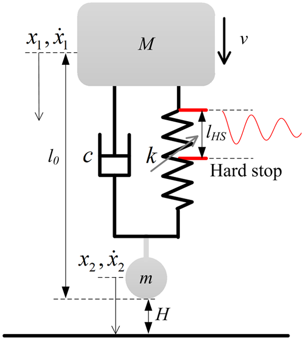
A spring–mass model to capture the landing dynamics of legged robots.
Related parameters with the spring–mass model.

Landing dynamics
In this article, we consider the situation of dropping freely the model from a certain height H, that is, no any active control action is applied during the entire impact process. When the lower mass m begins contacting with the ground from the air, corresponding ground reaction force is produced to balance the weight and inertial force. If we define the moment when m touches the ground as the reference time and use state variables

with the initial conditions
where
Investigated design parameters and evaluation metrics
For robotic designers, the following design parameters of distal compliance have to be determined before they start with hardware implementation.
Average stiffness
and preload
The first factor to be considered is how much compliance is required for a specific legged system, that is, average stiffness of the distal compliance over the allowable range of spring compression

In principle, more distal compliance (e.g. less average stiffness) is supposed to offer better protection to robots; however, it may also degrade the positioning accuracy of foot. The existence of the hard stop enables pre-compressing the distal compliance, and the preload Fpre (corresponding to pre-compression
Compliance profile
Most existing designs of distal compliance adopt linear configurations. Nonlinear profiles are hypothesized to be advantageous, but it is unclear what type of nonlinearity is a good fit. A range of nonlinear profiles with different degrees of stiffening/softening rates will be examined and compared. In particular, rather than seeking for a theoretically best nonlinear profile using optimization techniques, we hope to establish a general criterion for distal compliance design about the influence of nonlinearity (stiffening/softening rate) on impact buffering performance. Such a concept might give hardware designers a reference to what kind or degree of nonlinearity should be reasonably integrated in their robotic legs, according to the requirements of their systems.
The principal focus of this study of distal compliance is on impact buffering performance at touchdown. As a second reference point, we also consider the extent of compliance deformation during the whole impact process, although it has been bounded to a certain range by the hard stop. Correspondingly, the following aspects will metrically be assessed.
Impact magnitude and impact time
A high magnitude of force could cause structural damages to the robot hardware. Therefore, a relatively small magnitude of the impact force is desirable in legged locomotion. Rise time of the impact force is another key factor that should receive attention. Because, obviously, a short-duration impact can increase the likelihood of damage to mechanical system of robots due to high rate of force change, even with the same magnitude. Moreover, a longer rise time also leaves the active controller with more time to react to such instantaneous force.
Vibration amplitude
Compliance deformation would cause the torso (upper mass) to move and vibrate, which is particularly crucial for the systems concerning torso stationarity, for example, for those carrying laser or vision equipment to map unknown terrains. A bigger amplitude of vibration with the torso would add more noise and decrease sensing accuracy.
Numerical implementation
This section introduces simulation setups of the proposed conceptual model, including model of ground, model of distal compliance, and simulation procedure.
Modeling ground contact and distal compliance
In this study, the ground was modeled as a spring–damper unit, with the additional constraint that the ground cannot pull the foot downward. Hence, the ground reaction force was calculated as

where kG and cG are ground stiffness and damping coefficients.
A key goal of this study is to elucidate the role of compliance nonlinearity on impact buffering performance. In principle, the stiffness

where
Scenario 1:
Scenario 2:
Scenario 3:

Three scenarios of compliance profiles. Scenario 1 is characterized by a series of linear profile
Such first-order approximation is a considerable simplification but will allow us to conceptually identify which kind of nonlinearity might be better, softening nonlinearity, stiffening nonlinearity, or linear compliance? This doubt was inspired by the consensus that nonlinear characteristics may provide more benefits and is a more straightforward extension of such consensus. With the aforementioned setups, we are able to gain an insight as to how compliance nonlinearity affects the impact buffering performance, by varying the linear coefficient
One might argue that the performance is likely to be further improved if more flexible compliance behavior was employed. This may be true, but, in a sense, more flexible compliance, with multi-turning points, for example, mean more costly mechatronic design and control complexity. It is therefore, from the angle of physical implementation, not necessarily suitable due to the limits in current state-of-the-art technologies. In addition, the compliance characteristics revealed in biological components are consistently monotonic, implying that more complex compliance profile is not necessary.16–18
Simulation procedure
With the above preparations, we implemented the proposed models in MATLAB (R2014b; MathWorks Inc., Natick, MA, USA) together with the SimMechanics toolbox. An exhaustive search was performed during the simulation. The system dynamics was solved by using the Runge–Kutta fourth-order method (ode45) with a maximum time-step size of 0.01 s.
Simulation results
The results obtained with our conceptual model are reported in this section. Through the numerical experiments, we first explored the general impact behaviors of leg landing, without considering the action of active impedance modulation. Then, the effects of the design parameters proposed in section “Investigated design parameters and evaluation metrics” were investigated in detail. To generalize the results, we normalized those investigated parameters with respect to upper mass M, gravity g, and allowable range of spring compression
Impact behaviors
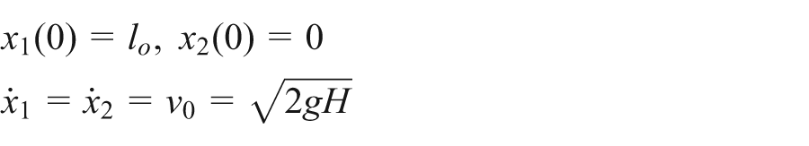
In order to obtain a general idea concerning the leg–ground interaction process after landing, we first carried out a series of preliminary simulation tests with three different distal compliance configurations, that is, without distal compliance, with a constant stiffness coefficient
Ground reaction force (left axis) and distal length variation (right axis) of the spring–mass model when landing from the height of 1 cm. The compliance configurations of (a), (b), and (c) are as follows: without distal compliance and with a constant stiffness coefficient
Then, the second peak caused by the upper mass M arises, marked by small rectangles. For the case of no distal compliance, the upper mass will act directly to the lower mass, thereby the ground without any deceleration leads to a high-magnitude peak (≈290 N, Figure 4(a)). In contrast, a degree of buffering will be provided in the case with distal compliance, resulting in a significant reduction in the peak force together with an extension of the impact time (Figure 4(b) and (c)). It is noted that a collision between the internal mechanical components would be caused (Figure 4(b)) if the distal compliance is too “soft.” Since too soft compliance cannot provide sufficient buffering force within the allowable compression range to balance the weight and inertial force of the upper mass, the upper mass cannot be supported properly and hits the lower mass. Such collisions would lead to a sudden increase in the peak force (Figure 4(b)) and therefore are damaging to mechanical components. Correspondingly, a degree of compliance deformation would be produced if having compliance in the distal segment (Figure 4(b) and (c)).
In the remainder of this section, we will systematically explore the influence of several design parameters proposed in section “Investigated design parameters and evaluation metrics” on the impact behavior and reveal how to more effectively design distal compliance for robotic legs.
Average stiffness and preload
The first issue we are interested in while designing distal compliance is how much compliance is required for a particular system. To analyze this, we set the distal compliance to be linear and vary the corresponding stiffness k from
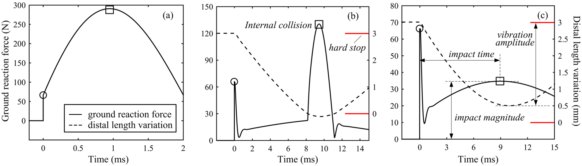
Figure 5 displays the observed impact magnitude as well as the corresponding impact time (see section “Investigated design parameters and evaluation metrics”), with different average stiffness. The gray region represents the spring stiffness values at which internal collision takes place, suggesting that low-average stiffness compliance is not suitable. Such suggestion is consistent with the results in Figure 4(b). With increasing spring stiffness, a growing trend in impact magnitude is observed, accompanied by a decrease in the corresponding impact time.
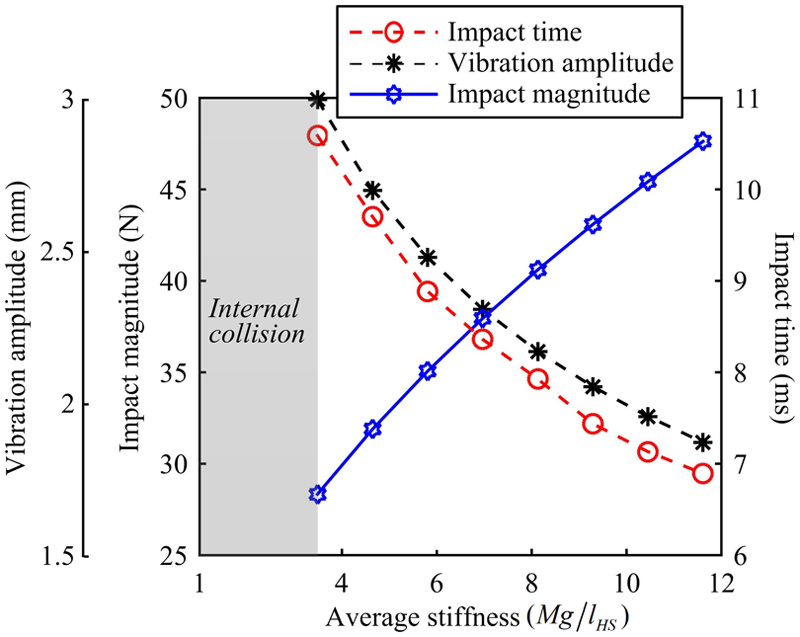
Impact magnitude, impact time, and vibration amplitude with respect to average stiffness. Gray region represents those average stiffness values at which internal collision takes place.
In terms of vibration amplitude (Figure 5), a decreasing gradient with respect to average stiffness is seen, suggesting that high-stiffness springs are favorable for those robots needing to keep torso steady, for example. This is true because for springs needing to produce a certain restoring force, the bigger the stiffness, the less the compression. Extrapolating from these findings, it could be expected that there is likely to be a preferable (range of) average stiffness in the distal compliance for a specific system.
Figure 6 shows the effects of preload. With increase in preload, an increasing trend is found in impact magnitude, while impact time is seen to decrease. These variations occurred because when compression occurs, the pre-compressed force would apply directly to the upper mass and to the lower mass and thereby to the ground, without need of any operating time. Vibration amplitude decreases as preload increases. Because the pre-compressed force can be part of the supporting force to balance weight and inertial force of the upper mass, less compliant force (and thus spring compression) is required. Additionally, the effects of increasing preload are similar to those exhibited by increasing the average stiffness (Figure 5), suggesting that the increased preload is able to, in a sense, make up for the shortfall in average stiffness of distal compliance. In other words, with the exception of directly increasing the stiffness of distal compliance, these findings provide us with an alternative way of advancing leg distal stiffness.

Influences of preload on (a) impact magnitude, (b) impact time, and (c) vibration amplitude.
It should be noted that these numerical results can also be obtained analytically. During impact, the lower mass m is always on the ground, thus its position

With the compliance configurations described above, substituting
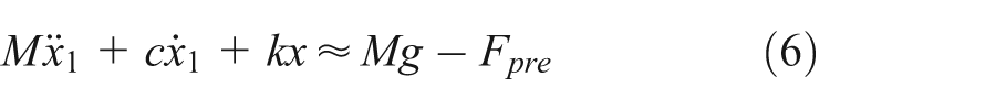
By solving equation (6), we can know how average stiffness and preload affect impact time and vibration amplitude. In addition, the total impulse

where

Owing to momentum conservation, the change in momentum should equal impulse resulted from the impact, therefore the following can be determined after rearranging

In particular, at the time

As equation (10) above describes, a low-magnitude ground reaction force entails long contact time. In turn, a high-magnitude impact is inevitably associated with a short impact time.
Analysis for various nonlinear compliance profiles
So far, we have examined average stiffness and preload and explained how they affect the impact behavior. In the following, we will characterize the possible role of variable compliance in impact buffering. To this end, another set of simulations was conducted by using a number of nonlinear compliance profiles defined by CNL and CL, as explained in section “Modeling ground contact and distal compliance.” The other related parameters were the same as in the previous simulations. In particular, to allow for a fair assessment of the respective advantages and disadvantages of compliance variations, a group of compliance profiles with the same average stiffness was compared, defined by equation (2). A basic mapping with the setup in section “Modeling ground contact and distal compliance” is as follows:
Figure 7 summarizes the behavioral changes for five different average stiffness values

Influences of compliance profile on (a) impact magnitude, (b) impact time, and (c) vibration amplitude.
However, the results in Figure 7(b) reveal an interesting feature. With linear coefficient CL increasing from 0.5 Kave to 1.5 Kave, the corresponding impact time is shortened by roughly 1.1 ms. This trend means that despite no significant effect on impact magnitude, stiffening compliance (CL < Kave) is able to extend the impact time, earn more reaction time for active controller, and therefore provide better buffering performance. Such benefit is gained likely because that the buffering effect at the early stage of impact is more crucial due to high impulse of the upper mass at that stage and that the effective stiffness at the beginning of compression with stiffening compliance profiles is relatively lower. According to the findings in Figure 5, a lower stiffness value corresponds to a longer impact time. With the same reason, the observation in Figure 7(c) that stiffening distal compliance corresponds to a larger amplitude of vibration can be explained.
An application case
In this section, we apply the proposed model to our six-legged robotic platform HITCR-II. The distal compliance in its legs was set initially to be constant stiffness 2.9 N/mm with a preload of 5.8 N. According to the results of numerical simulations, such configuration would probably cause internal collision if dropping the robot from 1 cm height. Being aware of that, we changed it to 9.8 N/mm with a preload of 19.6 N. This is already a good example that using the conceptual model guides the design of actual robotic system. In the following, we will introduce the robotic platform first, then present a series of experimental analysis to (1) show how the conceptual model can be applied to legged robots and (2) check whether the numerical results are suitable to predict impact behaviors.
The robotic platform
Our robot HITCR-II (Figure 8(a)) consists of a torso and six identical legs attached to the torso. Each leg has three segments connected by joints, from proximal to distal: coxa, femur, tibia, and a rubber pad at the bottom of the tibial segment to help hold onto and isolate ground. The joints in each leg are powered by direct current (DC) servomotors each combined with a synchronous belt drive and a harmonic drive for speed reduction and torque amplification and measured by Hall effect position sensors. In the tibial segment, a passive spring mechanism, called distal compliance, is introduced to respond to ground impact on touchdown. In the implementation illustrated in Figure 8(b), the tibia segment was composed of femur–tibia (FT) joint link, spring, linear bearing, locating pin, and force sensor link, whose bottom half is able to sense ground reaction forces simultaneously. A brushed DC motor mounted at femur distal end turns the FT joint link, at the bottom of the FT joint link is a fixed linear bearing, the linear bearing is passed through by top half of the tibial link as a rod with a spring wrap around it, which results in a spring damping model from the mechanical vibration point of view. The linear bearing constrains the tibial link sliding linearly, and the travel of such mechanism is limited by a mechanical stop consisting of a locating slot and a pin. When contacting, a load is transferred to the joint link due to ground impact, leading to the joint link sliding linearly. At the same time, the spring is compressed, and as a result, the impact force is mitigated to a certain degree. More details about robot hardware, electronics, and control system can be found in Zhang et al.11,21
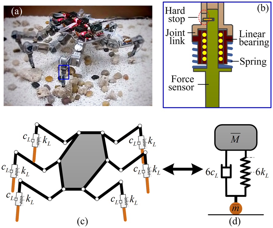
(a) Prototype of the HITCR-II six-legged robot, (b) diagram of the spring mechanism in tibia, (c) kinematic model of the robot leg, and (d) spring–mass equivalent model of the robot.
Application of the proposed model
As Figure 8(c) and (d) illustrates, the compliant mechanisms in robot legs can be viewed as the parallel combination of six spring–damper units. In this case, if we denote the spring and damping coefficients of each spring–damper unit by

Correspondingly, equivalent mass
Four test trials were performed first, with each test repeated 10 times. The aim of this series of experiments is to examine the matching degrees between the equivalent model (Figure 8(d)) and experimental platform, when various average stiffness and preload are equipped. The corresponding compliance setups were physically achieved using compression springs along with washers (MISUMI Group Inc., Japan), as described in Table 2. The ground reaction force and spring compression were monitored by the developed force sensors (sampling frequency of 1000 Hz, resolution 0.03 N) at feet as well as by a high-speed camera (Mega Speed Corp MS50 K, 500 fps, Canada). The video files were later analyzed using the associated graphic-tracking software to obtain the spring compression over time.
Distal compliance setups and realization.

The sum of the recorded forces at each foot and position data at the beginning of contact are plotted as a function of time in Figure 9. It can be seen that on the whole, the profiles of ground reaction force with the robotic platform can match approximately to those obtained with the equivalent model (Figure 8(d)), but with some differences in magnitude. Similarly, the spring compressions are observed to be smaller than the predicted ones (see the inset in each subfigure). These discrepancies could be caused by three error sources. The first is inter-leg coupling that is not accounted for in our models. Indeed, while dropping the robot by an experimenter, it is difficult to keep the six legs at the very same height; hence, the legs do not touch the ground at the exact same instant. This asynchrony leads to the distal spring compression not in one pace, influencing the distribution of robot weight to each leg and thus the ground reaction force at foot. The second error source is limited sampling rates of the force sensors (1000 Hz) and the high-speed camera (500 fps). Such sampling rates limit that the force data are recorded every 1 ms and the compression information are recorded every 2 ms. As Figure 9 shows, the time span of an impact event is around 8 ms or less. Taking these into account, the experimental measurements are in fact not accurate enough. Another possible reason is the mechanical deformations within legs. Such deformations can be, in a sense, viewed as kind of compliance and is an uncontrollable error in our case.
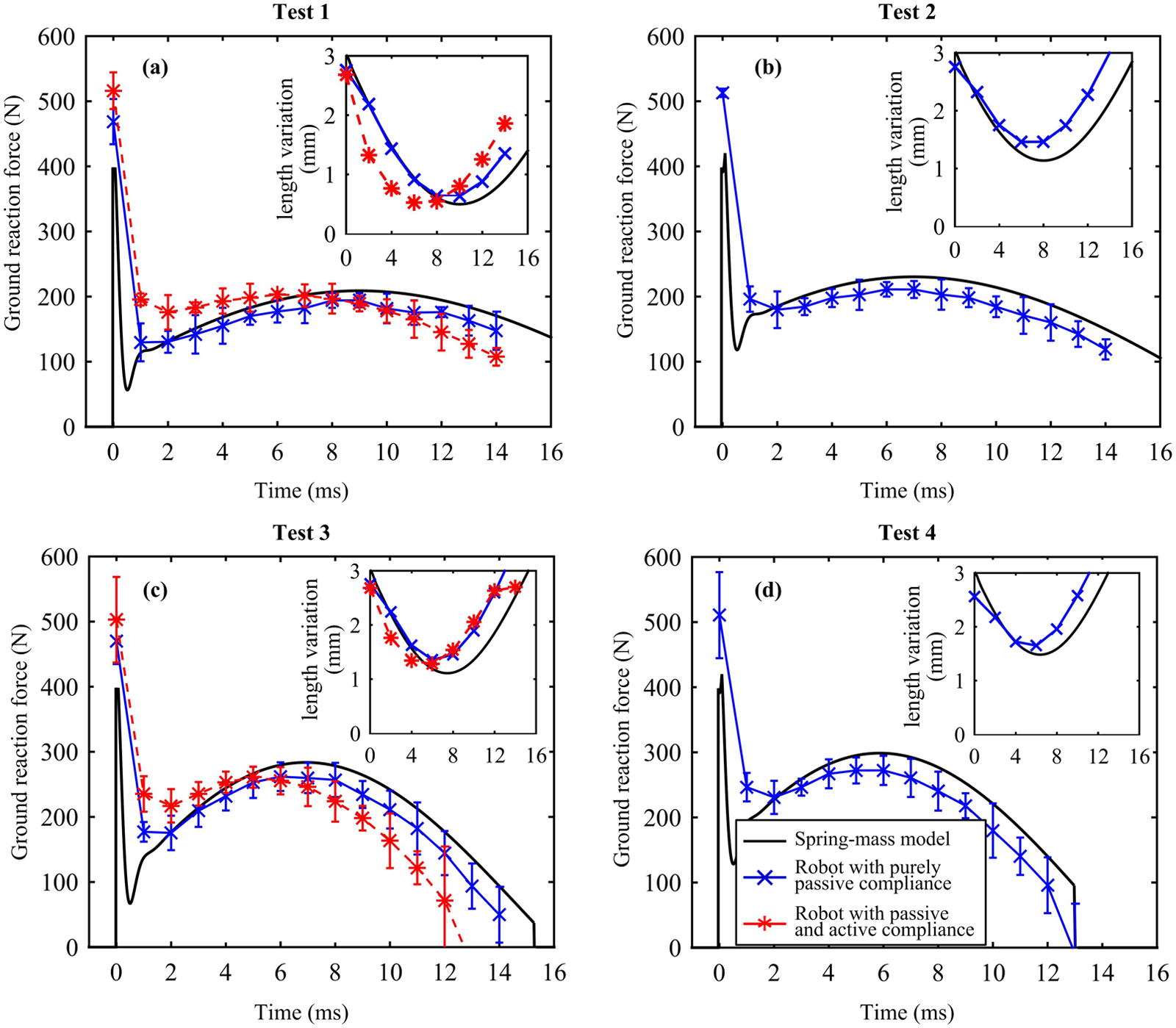
Ground reaction force and distal compliance deformation with the conceptual model and robotic platform.
Experimental analysis of nonlinear compliance profiles
It is physically difficult to test nonlinear configurations of distal compliance with the real-world robot. To solve this problem, an approach of combining passive compliance and active compensation was employed. Specifically, as depicted in Figure 10, the robotic legs were still equipped with the original linear springs (9.8 N/mm with a preload of 19.6 N), and the difference between the equipped and desired compliance behavior was compensated through actively retracting and/or protracting legs, as if nonlinear springs were placed. With this approach, nonlinear compliance behaviors can be produced in the distal end, without mechanically bulky and complex mechanisms. And more importantly, for this article, it enables an experimental validation of the reported conceptual model with the robotic platform. During each drop, each joint was controlled through a proportional derivative (PD)-based controller, and the distal segment was kept vertical during the whole contact process to improve the correspondence to the conceptual model.
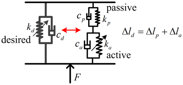
Schematic of the approach of combining passive compliance and active compensation to achieve desired nonlinear compliance.
To examine the effect of the active compensation approach, we conducted an ancillary study including two test trials. In this ancillary study, the robot achieved desired compliance configurations in two ways: (1) by purely passive compliance and (2) by the approach of combining passive compliance and active compensation. The specific compliance parameters can be found in tests 1 and 3 in Table 2, and the results obtained are presented in Figure 9(a) and (c), respectively. It can be observed that the experimental measurements can approximately follow the theoretical values, but with roughly 2 ms difference in time. This may be caused by the sensing, calculating, and executing processing with the real-world robot. The robot needs to actively sense the ground reaction force and calculate how much the legs should actively retract or protract. These processes would consume a certain time. In addition, to experimentally calculate the difference between desired compression
With the above validation of the active compensation approach, Figure 11 displays the ground reaction force and length variation in distal segments for various nonlinear compliance profiles of two average stiffness values, 9.8 N/mm and 19.6 N/mm, as examples. Still, the trends of experimental data are consistent with those obtained with the conceptual model, although slight differences exist in numbers due to the reasons outlined above.

Ground reaction force and distal compliance deformation with the conceptual model and robotic platform.
Discussion and conclusion
In this article, we have investigated the utility and design principles of the compliance characteristic located in the distal segments of legged robots, for impact buffering at touchdown. With a simple spring–mass model including realistic properties and constraints, we systematically examined the respective influences of compliance parameters. The numerical results indicate that sufficient average stiffness and preload, which may complement each other, are crucial to provide the upper torso with necessary supporting force therefore avoiding inelastic collision between the upper and lower components. On the contrary, too high average stiffness and preload could increase impact magnitude and decrease impact time, raising the change rate of impact force and thereby degrading the buffering performance. It therefore can be predicted that there likely exists a preferable (range of) average stiffness and preload for a specific system. By assessing nonlinear compliance characteristics with the same average stiffness and preload but different stiffening/softening rates, we found that despite no significant effect on impact magnitude, stiffening compliance is able to provide better buffering performance by extending the impact time. We believe this benefits from the relatively lower effective stiffness at the beginning of spring compression when with stiffening compliance profiles. Such lower effective stiffness is of great help at the early stage of impact when the impulse of the upper mass is particularly high. It is important to note that stiffening compliance behaviors were inevitably accompanied by a larger amplitude of spring compression, indicating that necessary trade-off has to be made for those systems concerning torso stationarity, which is also the key lesson we learned from this study. The experimental data with our hexapod robotic platform agreed reasonably with the results found with the proposed model, indicating that the conceptual model reported is able to suitably reflect the foot–ground impact process after landing events taking place. As a result, it can be used as a guide toward designing proper distal compliance for robotic legs and also provide us with an understanding of actions of distal compliance during leg–ground interaction.
We wish to measure the effect of leg distal compliance of various setups on impact buffering at foot touchdown. A particular challenge in this context is how to deal with the coupling between different legs. This issue has been simply stated in the preceding sections. The coupling effect has a significant influence on the distribution of robot weight and thus on the foot force. A perfect way is, of course, to fully include it into the model. However, we have to carefully think about the consequences of doing so. First, the versatility would be degraded. Rather than limiting the model to a specific number of legs such as four or six, the built model is expected to work for robots with any number of legs. The inclusion of the coupling effect of a certain legs could influence its application to other multi-legged machines. Second, the complexity of modeling and analysis would be greatly increased. It is difficult to integrate universal dynamics equations that are applicable to any legged machines into the model. Even for a robot with a fixed number of legs, the differences in numbers, locations, and postures with legs and joints would also contribute to the resultant forces and positions. All the complexities can make it challenging to study fundamental mechanisms. Realizing these and considering the very objective of this article, for example, providing conceptual design principles of distal compliance for hardware designers, a full consideration of the details in our model would make the analysis more complicated, in our opinion, than necessary. Therefore, we choose to simplify the complicated coupling process by collapsing those legs in contact phase at the same time into one single ‘virtual’ leg, producing the simple spring–mass model. Although it does not have a faithful correspondence to segmented legged robot thus perhaps not being able to serve the control aspects, the model can function as be used as an effective template to guide the hardware design of leg distal compliance, as experimentally demonstrated in section “An application case.” There have been numerous studies using simple models to explore complex mechanisms of robots and animals.15,22–26 For example, Aguilar et al. studied a one-dimensional actuated spring–mass hopper and revealed that optimal jumps occur not at its resonant frequency but rather slightly above and below it. 25 Karssen et al. used an SLIP model comprising a point mass on a massless spring to investigate the effect of nonlinear leg springs on disturbance rejection behavior. 15 They found that the optimal leg stiffness profile is strongly nonlinear, and the corresponding disturbance rejection performance could be greatly improved. Typically, Full and Koditschek discussed in detail the relative roles and efficacy of templates, anchors, and complex systems. 27
A common problem found in both numerical and experimental studies is that the lower mass (foot) may repeatedly break and re-establish ground contact, a phenomenon called chattering. Such phenomenon is increasingly apparent, or even inevitable, when with high-stiffness and/or high-preload distal compliance. Foot chattering may lead to walking instability and thereby is clearly undesirable. The first way of avoiding chattering is therefore to limit “hardness” of the distal compliance, through either reducing the average stiffness or decreasing preload or a combination of both. Another solution is to include additional dissipation elements. This scheme derives from the cause of chattering that the impactive energy cannot be dissipated in time. With this motivation, researchers have investigated the use of controlled active damping in the feet of the quadruped robot HyQ. In the field of vibration control, there has been considerable interest toward introducing active damping elements.
Although observed in both numerical and real-world studies, foot chattering in real-world experiments was found less obvious than in simulations. This might be resulted from the inter-leg coupling of multi-legged robots, which was not taken into account in the conceptual model. When chattering takes place in part of the supporting legs, the weight distributed to the rest of the supporting legs increases, resulting in more compression in those legs, lowering the height of the torso, and thereby helping the chattering leg re-contact with ground more quickly. Besides, the rubber pads at the bottom of each foot, which were not included in our model, could help reduce the undesirable chattering, because these pads are also able to provide a degree of compliance and damping.
While the theoretical and experimental results indicated that nonlinear compliance behaviors may provide robotic legs with better impact buffering or smaller torso vibration compared to linear ones, several practical considerations with hardware realization have to be made. First of all, implementing nonlinear compliance usually needs additional mechanical designs, which leads to high system complexity, for example, manufacturing and operation. Notably, such design may add additional weight and inertia to the system, increasing, in return, landing force on foot. Also, it is unsuitable for small and lightweight platforms to integrate these complex nonlinear mechanisms. On the side of control, nonlinear property as well as the additional structural components may complicate the modeling, analysis, and parameter identification of the whole system. In sum, we have to think about whether or not the performance enhancement outweighs the complexity increase involved in doing so on the side of the overall system.
The proposed conceptual model provides hardware designers with a theoretical reference for distal compliance. A major advantage is its versatility. Indeed, the model could be applied to robots with any numbers of legs, without interfering with other complicated issues such as inter-leg coordination. Such simplification also enables the whole analysis tractable. Yet just because of this, the use of the presented model has several limitations. First, the inter-coupling effect should influence the force distribution among legs. The ignorance with our model therefore causes imprecise predications in terms of ground reaction force and compliant deformation in each leg, as demonstrated in Figures 9 and 11. Second, as mentioned previously, the compliant characteristics in other parts of robot structures (e.g. joints and foot end) are not modeled, leading to discrepancies between real-world and numerical results. In fact, all the compliance within the robots is supposed to contribute to the transmission and buffering of ground reaction force. Third, damping variations within the compliant mechanism are simplified as well. All these incomplete mapping may introduce errors to our predications. Our future work, therefore, will improve the model accuracy by reasonably removing these approximations. We emphasize ‘reasonably’, because, despite without a faithful correspondence to real-world systems, advantages in terms of ease of modeling and reduction of parameter dimensionality were indeed seen in our studies, simplifying data analysis thereby facilitating basic principles revealing. More importantly, we have to think about the transfer of the presented models to robotic prototypes, that is, practical constraints of state-of-the-art technologies. Obviously, a relatively complicated model is challenging for straightforward hardware realization, as discussed above. Only a relatively low dropping height (1 cm) was considered, largely because of the limitations of other mechanical components of the robot (the platform was designed for the exploration of slowly static walking over rugged terrains). Despite this, we believe it is sufficient to validate the theoretical analysis reported previously.
Footnotes
Acknowledgements
The authors would like to thank Dr Fumiya Iida for his help and useful discussions.
Academic Editor: José Tenreiro Machado
Declaration of conflicting interests
The author(s) declared no potential conflicts of interest with respect to the research, authorship, and/or publication of this article.
Funding
The author(s) disclosed receipt of the following financial support for the research, authorship, and/or publication of this article: This work was supported by the National Natural Science Foundation of China (Grant No. 51105101), National Science and Technology Ministry (2015BAF10B02), and the self-managed project of State Key Laboratory of Robotics and System at Harbin Institute of Technology (SKLRS200901A01). The first author (J.C.) was also supported by China Scholarship Council (CSC).
References
Supplementary Material
Please find the following supplemental material available below.
For Open Access articles published under a Creative Commons License, all supplemental material carries the same license as the article it is associated with.
For non-Open Access articles published, all supplemental material carries a non-exclusive license, and permission requests for re-use of supplemental material or any part of supplemental material shall be sent directly to the copyright owner as specified in the copyright notice associated with the article.