
Abstract
This article aims to provide an overview of applications of rapid prototyping–assisted conformal cooling channel and shows the potential of this technology in different manufacturing processes. This review article also reports one case study from open literature where rapid prototyping–assisted conformal cooling channel has been successfully used in the manufacturing process. This study concludes that rapid prototyping technique can replace conventional manufacturing for complicated structure conformal cooling channel which improves quality and productivity. The outcome based on literature review and case study strongly suggested that rapid prototyping–assisted conformal cooling channel might become standard procedure in manufacturing process in near future. Advanced technologies such as computer-aided manufacturing, computer-aided engineering, computer fluid dynamics, and rapid tooling made it possible to fabricate the conformal cooling channel. Rapid prototyping–assisted conformal cooling channel can easily transfer the simulation into actual fabrication. This article is beneficial to study the development and application of rapid prototyping–assisted conformal cooling channel in different manufacturing processes.
Introduction
Conventional cooling channels are machined in straight lines. This method produces inconsistent results because conventional cooling cannot provide reliable cooling all over the mold cavity. Nonuniform cooling across parts leads to longer cycle times, uneven cooling, warpage, and scrap. Conformal cooling channel (CCC) shows potential alternative with increasing acceptance. 1 Cooling channel in shape of the part is called as CCC. Figure 1 shows the straight-drilled (conventional) and conformal (non-conventional) cooling channels. The main advantage of CCC is that it reduces cooling time and provides uniform cooling. CCC has been proven more efficient as compared to the conventional cooling channels in terms of a rate of production and accuracy of molded parts.3,4

Conventional and conformal cooling channels. 2
Some of the geometries required in CCC are impossible with traditional machining. Rapid tooling (RT) is the advanced manufacturing technique which is widely used for the CCC fabrication. These RT methods are classified into two types, namely, as direct and indirect RT. In the direct RT, molds are directly fabricated using rapid prototyping (RP). In the indirect RT method, a RP pattern is converted into a mold using secondary manufacturing techniques. 5 In this article, a systematic review of the literature was conducted, based on the application of RP-assisted CCC used in various manufacturing processes.
Evolution of RP-assisted CCC
In previous practices, cooling system improvement is based on optimization of conventional cooling channel. Conventional cooling channel gives nonuniform cooling, and it require more cooling and cycle time. Because of the limitation of this technique and due to advanced manufacturing technique such as RP, CCC came into existence.
Initially, the concept of RP-assisted CCC is used for injection molding application. Slowly, it starts utilizing in various manufacturing process, and nowadays, it is being offered. For the fabrication of complicated type CCC, various advanced RT processes used for the fabrication of metal mold are selective laser sintering (SLS), direct metal laser sintering (DMLS), and three-dimensional (3D) Keltool. These techniques are capable to withstand the conventional molding pressure and temperature. 5
RP-assisted CCC fabrication
RP-assisted CCC fabrication process is divided into two phases: first, computer-aided design (CAD) modeling and simulation and, second, physical fabrication using RT. Generalize standard process for development of RP-assisted CCC and its application in various manufacturing processes are illustrated in Figure 2.

Generalized standard procedure development of RP-assisted CCC for various applications.
Modeling and simulation of CCC
The improvement in computer technology, CAD, and computer-aided engineering (CAE) to design CCC is moving greatly in various applications such as injection molding, blow molding, hot stamping, hot extrusion, and die casting. Advanced CAD modeling and simulation software are capable to design complex, intricate, and compact-shaped CCC, which helps to improve uniform cooling and reduces the cooling time.
Different CAD modeling softwares are used for design of CCC based on part design. For the simulation of CCC, different softwares are being used. ANSYS and ABAQUS are often used for the thermal analysis, where as Moldflow, C-Mold, and Moldex3D are specially developed for analysis of CCC in dies. Table 1 shows the different approaches of simulation of conformal cooling.
Simulation-based approach of CCC.

CCC: conformal cooling channel.
Different structures of CCC
As advances in CAD modeling and RP technique, designing and fabrication of CCC in different complicated shapes is easily possible. Various authors checked the feasibility of CCC based on different structures for uniform and reduction of cycle time.
The benefits of CCC for injection molding were evaluated by different researchers using design of experiments (DOEs). The work presented an overview of the mold design methodology, cooling channel simulation and analysis, and tool production through MIT’s 3D printing (3DP) process. The simulation results showed that CCC reduced both cycle and cooling times and part shrinkage. 15
In 2007, Au and Yu 7 recommended a scaffolding architecture for CCC design. The comparison of mold cavity with and without scaffolding structure was studied using simulation technique (Figure 3). Moldflow analysis of the porous scaffolding structure was done using Moldflow plastics insight 3.1. The scaffold cooling system provided better cooling in mold cavity. They found greater surface area for the cooling in scaffolding cooling system as compared to the conventional straight-drilled and copper duct bending cooling systems, resulting in uniform distribution of heat.

Injection mold half without and with scaffolding architecture. 7
Fin concept was used for improving efficiency of CCC by Hearunyakij et al. 16 In another study, the authors compared results of square section conformal cooling channel (SSCCC) with conventional straight cooling channels (CSCCs) in an injection molding process using Moldflow plastic insight software (Figure 4). The simulated results confirmed that using polypropylene (PP) and acrylonitrile butadiene styrene (ABS) as plastic materials with normal water at 25°C as a coolant reduced the cooling time by 35% with the SSCCC as compared to the CSCC. Also, cycle time was reduced by 20% using the SSCCC than CSCC. 8

CSCC and SSCCC. 8
The CCC using an array of baffles was investigated by researcher in the plastic injection molds for a radiator grill with ABS 750 material (Figure 5). The performance of cooling channels was evaluated and compared the results of an array of baffles with the straight cooling channels using Moldflow software. From the analysis, the temperature variation in cooling channel with an array of baffles was improved by 49.41%, which is more uniform as compared to the straight cooling channels. 11
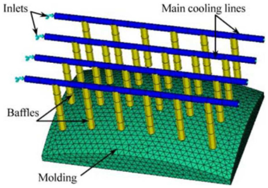
Array of baffle cooling channels. 11
In another study, researcher compared the results of profiled cross-sectional CCC (PCCC) with circular cross-sectional CCC (Figure 6). Both channels were designed with 78.5 mm2 cross-sectional areas and normal water at 25°C as a coolant. The thermal distribution in both the CCCs was simulated using ANSYS. Result showed that 14.6% increase of heat flow with PCCC. 13

Mold with circular and profiled cross-sectional CCCs. 13
In 2011, Au and Yu 17 proposed an alternative design method for a CCC with multi-connected porous characteristics based on the duality principle (Figure 7). The proposed method provides a more uniform cooling performance than the existing CCC design.

CCC with multi-connected porous structure. 17
Wang et al. 18 investigated a geometric modeling Vornoi diagram (VD)-based algorithm to design the cooling circuit approaching CCC. Figure 8 shows the steps of cooling circuit generation. As compared to previous methods, this approach offered the advantages of automatic generation of CCC as per the shape of products. The results showed that this method effectively reduced the cooling time and controlled the uniformity of temperature and volumetric shrinkage. The limitation of this algorithm was that it requires iterative optimization procedure to adjust the cooling channels by correcting the cycle time.
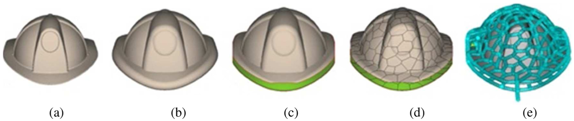
Steps of the cooling circuit generation using algorithm: (a) part model, (b) the offset surface of given model, (c) the separated offset surface served as the conformal surface, (d) the refined discrete CVD, and (e) the resulting CCC circuit. 18
A novel adjustment method for cooling distance modification between the CCC and its mold cavity (or core) surface along the cooling channel was presented (Figure 9). The method can balance the gradual increase of the coolant temperature from the coolant inlet to the coolant outlet. More heat can be transferred from the mold surface near the coolant outlet to the variable distance conformal cooling channel (VDCCC). 19

Conventional CCC and variable CCC. 19
Muhammad Khan et al. 14 designed different types of cooling channels, namely, conventional cooling channels, series CCC, parallel CCC, and CCC with additive cooling lines for cooling of a food container (Figure 10) and compared the results using Autodesk Moldflow Advisor 2013. Simulation results have shown that CCC lines gave better cooling as compared to conventional cooling lines, but using the additive cooling lines with CCC provided even more uniform cooling and took less cooling time.

(a) Conventional cooling channel design, (b) series CCC design, (c) parallel CCC, (d) CCC with additive cooling lines. 14
In 2015, Wang et al. 20 introduced a new approach for generation of spiral CCC and compared with VD-based CCC (Figure 11). They found less cooling time with spiral CCC than VD-based CCC.

VD-based and spiral CCCs. 20
Brooks and Brigden 21 introduced the concept of CCC layers which provides higher heat transfer rates and less variation in tooling temperatures. The cooling layers are filled with self-supporting repeatable unit cells that form a lattice throughout the cooling layers. The lattice improves convective heat transfer.
Rapid fabrication of CCC
The term “RT” means fabrication of tooling using RP. RP technique is a solid freeform fabrication process which plays a vital role in the fabrication of complex CCC structures in injection molding which otherwise very difficult to fabricate using conventional manufacturing process. Karunakaran et al. 22 have discussed different rapid manufacturing techniques for metallic objects. They classified rapid manufacturing into six groups such as computer numerical control (CNC) machining laminated manufacturing, powder-bed technologies, deposition technologies, hybrid technologies, and rapid casting technologies. Among them for the fabrication of complex-shaped CCC, powder-bed technologies are being used. Nowadays, various advanced powder-bed technologies are available for the RT-like direct metal deposition (DMD), DMLS, SLS, direct metal tooling (DMT), selective laser melting (SLM), direct laser fabrication (DLF), and laser-engineered net shaping (LENS). Many researchers have been carried out RT-based approach for fabrication of CCC in injection molding (Table 2).
Fabrication of CCC through RT.

RP: rapid prototyping; CCC: conformal cooling channel; PP: polypropylene; ABS: acrylonitrile butadiene styrene; POM: polyoxymethylene; SDM: spray deposited metal; DMT: direct metal tooling; SLS: selective laser sintering.
A modular concept was proposed where parts of the tool were manufactured by traditional methods, whereas inserts were fabricated by SLS. This modular concept reduced cost and lead-times. 27 DMD and spray deposited metal (SDM) used to reduce the cycle time without sacrificing any part quality or wear of the tool. 28 Rapid laminated tooling was used and showed an improvement in part quality and reduced the cycle time as well as reductions of costs and lead-times in the manufacturing process in comparison with the conventional machined tools. 29 It was reported that time savings was up to 30% using SLM for manufacturing inserts. High thermal conductivity cooling is another way of cooling tools without manufacturing of complicated cooling channels. 30 Laser-assisted metal RT process was used for the fabrication of mold and forming tools. The development of the fabrication of the mold with CCC and thermally conductive mold with a volumetric heat sink ensured the uniformly heat transferred for the rapid cooling. These types of mold improved the productivity and quality of the molded parts. 31 Rannar et al. 24 fabricated the mold insert with Arcam H13 tool steel using electron beam melting (EBM), and polyoxymethylene (POM) was used as a plastic material (Figure 12).

Insert fabricated by EBM. 24
The methodology for core and cavity was demonstrated for the injection molding (Figure 13). The green part of an injection mold with CCC system design was made by MIT’s 3DP. 32

Green parts of an injection mold with CCC design made by MIT’s 3D printing. 32
The CCC on a fan blade was fabricated using the laser-aided DMT process in which KP4M material was deposited with 1-mm steel P21 (Figure 14). 25
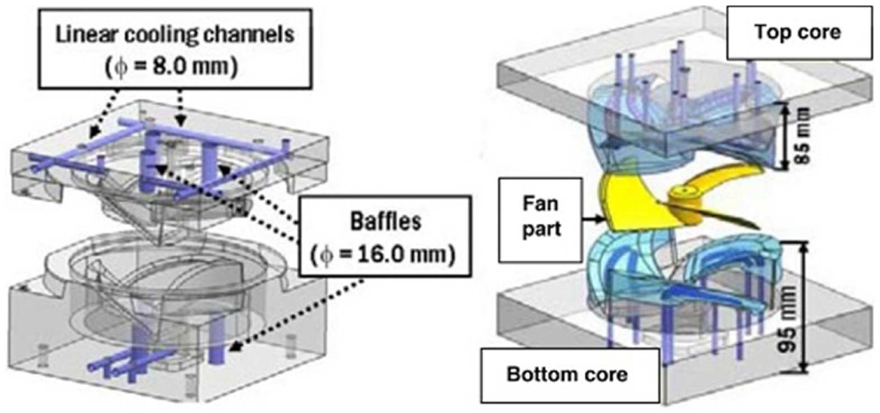
Rapid tooling with linear and CCC. 25
A significantly higher cooling efficiency was achieved using a flood cooled insert manufactured by EBM, resulting in reduced cooling times and a more homogeneous temperature distribution in the mold, but the effect of changing the coolant temperature was not investigated. 33 A steel modular insert was fabricated using SLS for the injection molding process. This material consisting of a polymer-coated stainless steel powder was infiltrated with bronze, which offers P20 steel hardness and durability, high thermal conductivity, and the material cost is expensive and not suitable for large parts. 26 The mold with the CCC was fabricated by RT with a composite material of aluminum filled epoxy (Figure 15). The cooling channels were inserted with a bending copper duct before the epoxy filling process. 23
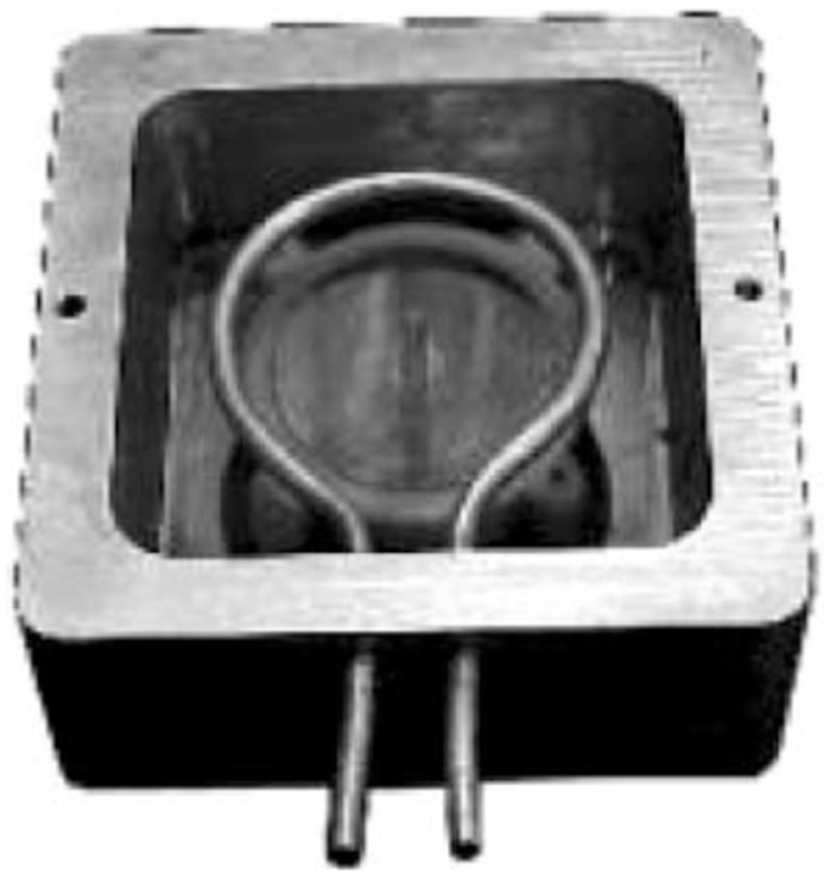
Soft RT mold with copper duct CCC. 23
Stainless steel powder was used in 3DP process for fabrication of injection mold with experimental testing and finite difference approaches. Thermocouples were placed on the core and cavity sides to monitor the mold surface temperature. 34 Altaf et al. 2 presented a technique for the manufacture of cooling channels of different profiles in epoxy molds. Experimental analysis for temperature measurement for the molded part with injection molding process showed that PCCC mold has less cooling time than mold with circular channels (Figure 16).

Circular and PCCC mold cavities. 2
Eiamsa-Ard and Wannissorn 35 discussed a hybrid approach for fabrication mold with conformal bubbler cooling by metal deposition method (Figure 17).

Fabrication steps for mold with bubbler cooling. 35
Application of RP-assisted CCC in different manufacturing processes
Various researchers have reported the influence of RP-assisted CCC in different manufacturing processes. Some areas in which RP-assisted CCC has been successfully used are discussed below.
Injection molding
Cooling system improvement is an emerging area of research in the plastic injection molding. Injection molding process is cyclic in characteristic. Filling, packing, cooling, and ejection are the steps of the injection molding process. Among the number of stages involved in injection molding of plastics, cooling stage is a very important stage as it affects the productivity and mold quality. Dimla et al. 3 used Moldflow software for optimizing the gating system and designing of cooling channels for uniform temperature distribution. In 2007, Saifullah and Masood 4 used ANSYS for thermal analysis of straight-drilled cooling and CCC. The efficiency of the conventional straight drilled and CCC was compared with results such as warpage and cooling time using Moldflow software.10,12,36
Blow molding
Blow molding is a process to produce hollow-shaped parts. The cooling stage takes up approximately two-thirds of the complete blow molding cycle. Application of CCC in blow molding can improve the productivity and quality of blow-molded part. The cooling time and the quality part are controlled by an adequate cooling channel design inside the blow mold. Au and Yu 37 proposed an effective method for CCC design in blow mold with the integration of CAD and CAE tools in order to improve the cooling performance of the blow mold during the blow molding process. Moldflow software was used to simulate the temperature distributions.
Hot extrusion
CCC in extrusion dies decreases the profile’s exit temperature and avoids thermally induced surface defects, such as hot cracks, in order to raise the productivity in hot aluminum extrusion. A mandrel of an extrusion die with CCC (Figure 18) was manufactured in a powder bed of CL50WS in a nitrogen atmosphere using a LaserCUSING machine. 38

Mandrel of an extrusion die and geometry of the channels manufactured by laser melting. 38
Hot stamping
During hot stamping process, the steel sheet is heated up to the austenite temperature range in a furnace until a homogeneous austenitic microstructure is obtained. Then, the steel sheet is transferred to the press and subsequently formed and simultaneously quenched in the closed tools with a cooling system to produce the intended shape. The components finally exhibit a martensitic microstructure. CCC in hot stamping dies plays dominant role in quenching process. B He et al. 39 proposed a new longitudinal CCC design in a B-pillar tool for application of hot stamping dies.
Die casting
CCC in die casting application improves the surface finish of castings due to a reduced need of spray cooling, which is allowed by a higher and more uniform cooling rate. Secondary benefits include reduction of cycle time and shrinkage porosity. Armillotta et al. 40 fabricated casting die with CCC by hybrid method half portion with CNC and half portion with SLM (Figure 19).

Hybrid construction of casting die. 40
Case study
In this section, one case study from the open literature has been considered for discussion which presents application of RP-assisted CCC.
Au and Yu 37 proposed an effective method for CCC design in blow mold with the integration of CAD, CAE, and RT tools in order to improve the cooling performance of the blow mold during the blow molding process (Figure 20). The following are the steps for development of CCC in blow molding:
First the geometric model of the blow-molded part, that is, a water container in this study, is designed in a surface (or solid) model using a CAD tool (e.g. SolidWorks or Rhinoceros 3D).
The design of the mold halves was used for the case study, and the dimensions of the mold cavity are 200 mm × 200 mm × 100 mm (L × W× H) using another commercialized CAD tool (e.g. 3D Quickmold).
Design and creation blow mold with integration of CCC.
CCC design is generated by a CAD sweeping process from the geometric modeling. The solid model of CCC was subtracted to form a 3D hollow passageway by Boolean subtraction. The cooling channel diameter is set to be 8 mm according to the standard design guideline.
CAE analysis was applied to support the designer’s judgment for the feasibility of the cooling channel design or other attributes related to blow molding.
The proposed CAD blow mold design was fabricated by the advanced RT technology SLM in order to form the physical mold model with a complex internal hollow structure of the CCC design.

Steps for development of CCC in blow mold. 37
The advantage of this technique is that CCC is used for improving the cooling performance of blow molding process. An advanced RT technology of the SLM process is explored and recommended for the direct and rapid fabrication of blow mold integrating CCC in a single operation in this study.
Discussion
The purpose of this review work is on the applications of RP-assisted CCC and shows the potential of this technology in different manufacturing processes. This review article also reports one case study from open literature where RP-assisted CCC has been successfully diversified. Fabrication methods for the injection mold with CCC under the RT are also discussed.
Many researchers have studied the designing of CCC on the basis of RT for the application of manufacturing process. The efficiency and performance of CCC are proven in terms of improvement on parts of deflection, the uniformity of thermal distribution, cooling time reduction, and the reduction in cycle time. However, most of the researchers only focused on simulation works and still lack supports and verifications from real experimental data. Research with only simulation could not fully solve the actual problems in real production. Time is very important when dealing with the product design and development. There is no mold-making company that would ever afford to take a risk to try a new approach of CCC without validation through experimental. This implies that the results are not beneficial to the manufacturing society. As such, extensive research involving experimental works should be conducted continuously to assist the molding company industries in particular small- and medium-sized enterprises in improving the quality of parts produced.
Conclusion
In this article, the outcomes based on literature review, applications, and case study are discussed. In future RP-assisted CCC might become a standard procedure in various manufacturing processes. After a detailed study of published research, main conclusions can be summarized as follows:
RP technique could replace conventional manufacturing for complicated structured CCC which improves quality and productivity.
In this field, the main focus is based on simulation work; still, more research is required for fabrication of mold with CCC.
Conventional manufacturing techniques are not suitable for effective fabrication of complex structured CCC in the mold; only advanced manufacturing techniques such as metal RP (SLS, DMLS, SLM, etc.) have the potential to create such type of complex structured CCC.
But mold formed from metallic RP technique is not suitable for industrial applications because of the high cost.
Nonmetal RP techniques such as fused deposition modeling (FDM), laminate object manufacturing (LOM), and stereolithography apparatus (SLA) can make such type of complex structured CCC inside the mold but still challenging to convert a green mold into a metallic one.
Footnotes
Academic Editor: Xichun Luo
Declaration of conflicting interests
The author(s) declared no potential conflicts of interest with respect to the research, authorship, and/or publication of this article.
Funding
The author(s) received no financial support for the research, authorship, and/or publication of this article.