
Abstract
With intensified energy restructure in China, energy efficiency of various industrial furnaces and kilns fired by natural gas draws attentions of more and more researchers. In this article, a field test was performed for shuttle kiln popular in ceramics and refractory manufacture industry. The thermal efficiency, main heat loss, and the energy-saving potential were evaluated, and the defects of the existing kilns and improvement measure were clarified. The results show that the overall efficiency was only 13%–15%, if measured in terms of the entire heating period. The energy loss of flue gas accounted up to 50%; the effectiveness of air preheater was as low as only 30%; large amount of cold air infiltration was observed at the venting exit at the bottom of the kiln. The burner controls and gas flow within furnace remain to be optimized.
There are several hundred thousands of industrial furnaces and kilns in operation in China, accounting for 25% of national energy consumption, or equivalent to 60% of industrial energy consumption.1–4 Among fuel-driven furnaces and kilns, solid fuel (coal) accounted for 70% while liquid fuel (oil) and gaseous fuel (gas) accounted for only 20% and 10%, respectively. Electricity-driven furnaces accounted up to 45% in terms of numbers of sets, but contributed only 8% of industrial furnace energy consumption. 5 The energy efficiency of industrial furnaces and kilns varies with their types and functions. It was estimated that the average efficiency was lower than 36%,6,7 in comparison to the average efficiency above 50% in the developed countries.8,9 Undoubtedly, it is essential to improve furnace and kiln efficiency in China, therefore, to reduce energy consumption and to promote sustainable development of energy industry as a whole, a great deal of methods such as heat recovering have been undertaken.10–14
With in-depth energy restructure and increasingly stringent environment regulations, a number of coal-fired and oil-fired furnaces (and kilns) in many industries were converted into natural gas in recent years. Unfortunately, many design concepts, structures, and operation remain unchanged, resulting in higher energy consumption and unimproved product quality. Research on thermal behavior of gas-fired kiln can improve energy efficiency and provide guidelines for reasonable designs.
Being a popular method to research thermal behavior of modern furnace (and kiln), field test is always difficult or even impossible to implement because of higher cost and long duration required. From 1960s to 1980s, some energy balance measurement and tests had been carried out in China, and related standards for measurement of some industrial furnaces (and kilns) were established. 15 In early 1990s, some performance data of refractory manufacture furnace were experimentally determined. 16
Recently, furnace (and kiln) diagnostics aiming at energy conservation began to draw attentions of researchers accompanied with increasing gas prices. In this article, a shuttle kiln which manufactures refractory was measured and analyzed to determine operation parameters within a production period. The energy balance was calculated to analyze its efficiency, energy losses, and potential to save energy. The shortcomings of the present design were revealed, and modification direction was clarified.
Shuttle kiln system
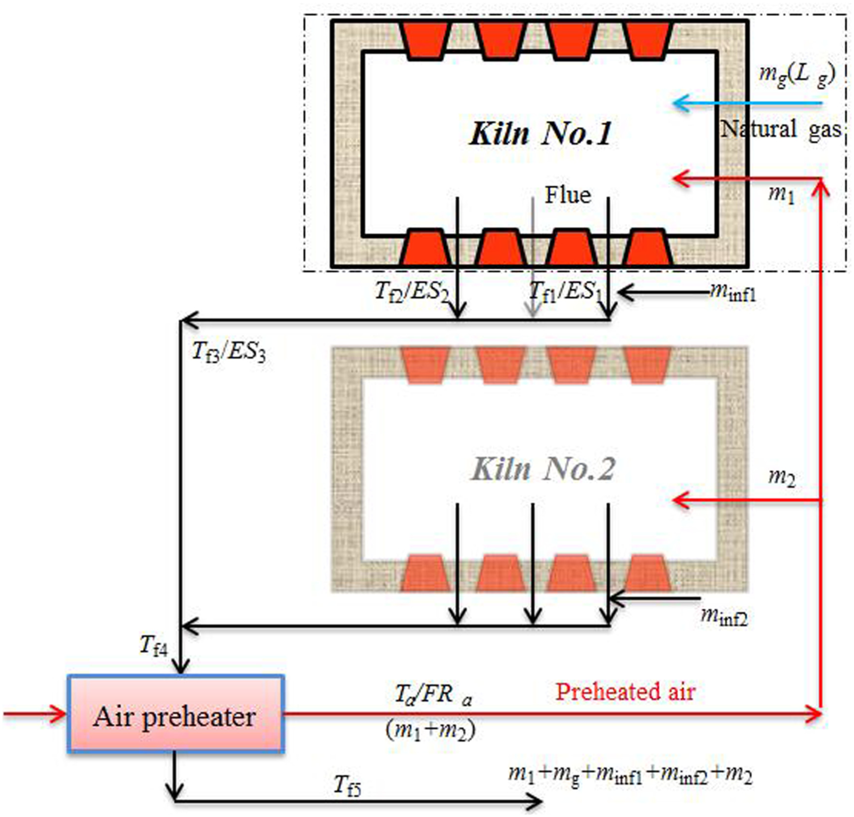
A shuttle kiln system was selected for in situ measurement. Its products were refractory such as corundum brick and alumina bubble brick. Being one type of most rapidly developed kilns in the past decade in China, the shuttle kiln was suitable for small-quantity production and always lined with lightweight refractory bricks. As shown in Figure 1, the system consisted of two kilns, namely, No. 1 and No. 2, which shared one set of air delivery system and venting system. Each kiln was equipped with eight non-aerated burners located on the side walls. There was an underground venting tunnel made of refractory bricks underneath each kiln, and flue gases entered the venting tunnel through three venting exit at the bottom of the kiln. Gases from two venting tunnels mixed and passed through an air preheater prior to venting into atmosphere through chimney. Preheated air was delivered to burners through air conduits wrapped with 3-cm-thick glass wool.

Illustrations of the shuttle kiln and arrangement of measurement points.
The burners were not equipped with any automatic ignition, proportional controls, and flame failures. All the procedures were manually operated by working staff. The name of the “shuttle” system suggested its operation: when No. 1 kiln stops heating, the products would be cooled down gradually by air from the preheater; burners of No. 2 kiln start to work.
The side walls of the kiln consisted of three layers of refractory, namely, 100 mm of alumina bubble bricks, 300 mm of mullite brick, and 350 mm of lightweight alumina brick (from inner to outer). Both doors located in the front and the back of the kiln and the slightly vaulted top were composed of the same three layers. The kiln car was made of five layers of alumina bubble bricks with each layer being 1.61 m × 1.61 m. In the center of the kiln car, a 15 cm × 15 cm hole was arranged as the venting exit (Figure 2(c)). When raw refractory bricks were manually piled up before heating, an artificial channel of the same cross section was provided for flue passageway to connect with the venting exits (Figure 2(d)).

Some details of the shuttle kiln: (a) cross section of the kiln, (b) venting exit, (c) kiln car, and (d) flue passageway.
Instrumentations for measurement
Figure 1 shows the instrumentation to measure the thermal parameters of the shuttle kiln. A 5-m-long S-type (platinum rhodium–platinum) thermocouple was buried into a corundum brick to be processed, and all the remaining parts were surrounded by small porcelain rings to protect against high-temperature oxidation when exposed to flame. Some S-type thermocouples were arranged at the observation holes on the side walls to record gas temperatures at different locations. The temperatures of kiln brickworks were monitored by some S-type thermocouples embedded in the refractory of kiln front door. A number of K-type (nickel chromium–nickel silicon) thermocouples were placed at the venting exits, venting tunnels, venting manifolds, entrance of chimney, and inlet/outlet of air preheater, to continuously record temperatures of flue gases at different locations and air temperature. At the venting tunnel and venting exits of No. 1 kiln, a flue gas analyzer was used to sample at a flexible interval. A pitot tube was installed onto the exit of the air preheater to measure the dynamic pressure of air flow. The mass flow rate of air delivered was then calculated from the temperature and dynamic pressure measured.
In addition, the temperatures of kiln walls, various pipes’ surface, and ground surface in the neighborhood of tunnels were monitored by contact thermometer, radiation thermometer, and thermal imaging system.
During process heating period, the working staff manually adjusted gas flow rate according to experience to satisfy specific requirements. After every adjustment, gas flow rate, air flow rate, and flue gas component at the venting exits and venting tunnel were measured immediately. During operation time when there was no adjustment of gas flow rate, flue analysis was checked once every 30 min, and the wall temperatures and thermal imaging system were checked every 2 h.
Measurement results and analysis
Main operation parameters
During the field test, No. 1 kiln was in the “heating” mode with all burners “ON” while No. 2 kiln was cooled down. The measurement lasted for 87 h, and a number of performance data including time-dependent product temperature, air flow rate, flue gas components, flow rate, and so on were acquired. The operation data from burner ignition to shutoff, 3486 min altogether, were taken for calculation and analysis.
The flow rate of natural gas was adjusted four times, as shown in Figure 3. The total consumption was 4425.1 N m3 (lower heating value (LHV) of 34.457 MJ/N m3) during the heating period of 3486 min. The total mass of the products was determined by in-site counting to be 13,391 kg, including 2667 kg of corundum brick and 10,724 kg of alumina bubble brick.

Natural gas flow rate of shuttle kiln.
Figure 4 shows various temperatures recorded corresponding to the period from 300 min after ignition to 770 min after shutoff, including gas temperatures at different locations within the kiln (Tg1, Tg2, Tg3, Tg4), processed refractory temperature (Ts), flue gas temperature along passageway (Tf1, Tf2, Tf3, Tf5), and so on. It can be found that the highest temperature was about 1600°C and gas temperatures at different locations appeared to be of the same pattern with little variations. All the measured temperatures dropped quickly after the burners shut off.

Time-dependent temperatures of shuttle kiln.
It can be seen in Figure 4 that all the temperatures are changing with the natural gas flow rate, namely, the power. This can satisfactorily meet the technological requirements of refractory manufacture, and it is the most important advantage of shuttle kiln. It should be noted that the temperature at the inlet of the chimney (Tf5) was always higher than 200°C and peaked 400°C before shutoff.
The most interesting and valuable temperature was that of corundum brick, shown as Ts in Figure 4. The duration was from 235 min after ignition to 770 min after burners shut off. It can be found that the temperature dropped and oscillated at some time due to damage of protective ceramic rings. Figure 5 shows hot air temperature leaving air preheater and its mass flow rate, each of which was alternatively measured at point Ta/FRa.
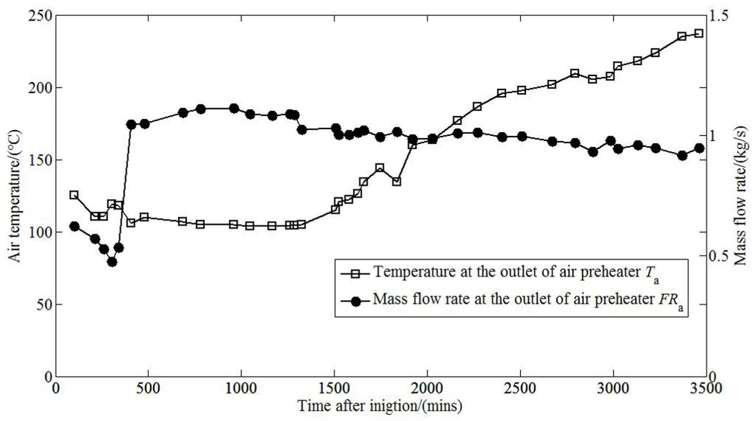
Temperature and mass flow rate at the outlet of air preheater.
Figure 6 illustrates time-dependent O2 contents of flue gas (and excessive-air coefficients α) measured at venting exit 1#, venting exit #2, and venting tunnel. Figure 6 shows flue gas analysis at different locations along flue passageway.
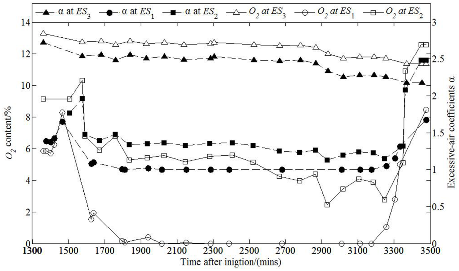
Flue gas analysis at different locations along flue passageway.
During heating period, the excessive-air coefficients at venting exit 1# and venting exit 2# were found to be 1 and 1.2, respectively, while the excessive-air coefficient at the venting tunnel was always higher than 2. This suggested that air supplied to the burners in the neighborhood of venting exit 1# was not enough and large amount of cold air was entrained at the venting exits due to the high velocity resulting from combustion.
Energy balance of shuttle kiln
For the measured shuttle kiln, energy balance within an entire period was analyzed. Considering the dashed-line frame as shown in Figure 7, energy balance within a specific time (

where
The energy balance analysis of the shuttle kiln.
For the refractory being processed, the internal energy change was calculated as equation (2)

where
Figure 8 shows a combined wall structure such as brickworks and kiln cars. For a given set of thickness of each layer, heat flux q at a specific time could be calculated if temperatures

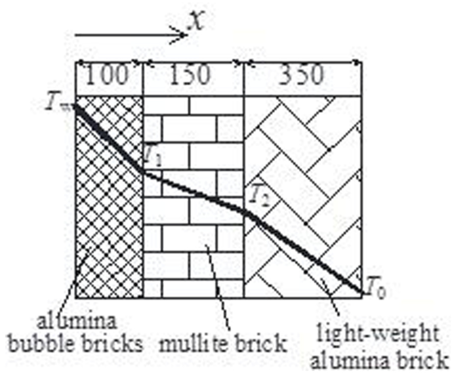
Heat conduction analysis of combined insulations.
The internal energy of each layer of a combined wall at specific time can be evaluated as

Accordingly, the change in internal energy turned to be

where F is the area of combined wall considered (m2); for the brickworks, the area is the sum of side wall, top wall, and both gates, altogether 52.12 m2; for kiln car, F is 7.77 m2.

where

where

where

in which
For every moment of calculations, the temperature at internal surface of brickworks Tw was taken as the mean of neighboring gas temperature and the temperature of brick being heated, both of which are given in Figure 4. The temperature at outer surface T0 was taken as the measured values.
The time-dependent internal energy of refractory being processed, brickworks, and kiln car was finally calculated and is shown in Figure 9. As a comparison, the enthalpy of flue gas leaving the kiln

Internal energy and flue gas enthalpy changing with time.
It can be found that with increasing temperature of processed refractory, its internal energy increasing rate began to drop due to decreasing temperature difference between hot gas within kiln and processed refractory. As shown in Figure 4, gas temperatures at all measured locations were higher than that of processed refractory until 1000 min after ignition, implying an effective heat transfer. For those periods 2500 min after ignition, only two measured gas temperatures were slightly higher than that of processed refractory, it suggesting a weakened heat transfer. Accordingly, energy carried by flue gas increased, which could be reflected as increasing flue gas temperatures. However, heat dissipated through wall surface and pipe surface remained almost constant during heating period, accounting for less than 1%. Unfortunately, the temperature of preheated air was not observed to increase with increased flue gas temperature; the gas temperatures would not be increased as well.
Taking
Energy balance of shuttle kiln (1625–3246 min).

The reason why this period was selected for energy balance was that all necessary parameters for calculation were systematically recorded or manually measured. As shown in Figure 4, some temperatures could not give reasonable readings until 1500 min after ignition.
According to related furnace (and kiln) test standards, 17 the performance for shuttle kiln should be measured from the beginning of heating until shutoff. Energy balance within the whole heating period was approximately evaluated as follows. At the beginning, the temperature of refractory brick processed Ts was below 300°C (the starting point of S-type thermocouple) and there was no effective reading. The temperature of kiln door was 160°C, while the temperature of the kiln gas Tg was 329°C. Assuming the temperature of refractory brick processed was between that of kiln door and kiln gas, its internal energy at the beginning could be calculated to be Es(τ = 0) = 3,432,219 kJ. When all the burners shut off, the temperature of refractory being processed was 1462°C, and their internal energy was Es (τ = 3449 min) = 26,879,821 kJ. Accordingly, the total increase in internal energy of refractory being processed was ΔEs = 23,447,602 kJ. The total natural gas consumption is 4425.1 m3 with 1.52 × 10⁸ kJ of input heat; therefore, the efficiency during the whole operation period was estimated to be approximately 15.4%.
Cold air infiltration at venting exits
As mentioned before, the air supplied to the burners in the neighborhood of venting exit 1# was not enough and large amount of cold air was entrained at the venting exits due to the high velocity resulting from combustion. The amount of infiltration air was calculated from measured Tf1, Tf2, Tf3, and Tf4 and is shown in Figure 10. It can be found that with increasing temperature of refractory being heated (Ts), heat transfer decreased and flue gas temperature increased, so did flue gas velocity crossing the venting exits. Given a fixed area for infiltration, the amount of infiltration air increased with increasing flue gas temperature. As shown in Figure 10, the infiltration air increased radically from 0.36 to 0.475 kg/s within the 60 min after the fourth adjustment of gas flow rate. Afterward, the infiltration air remained almost constant.
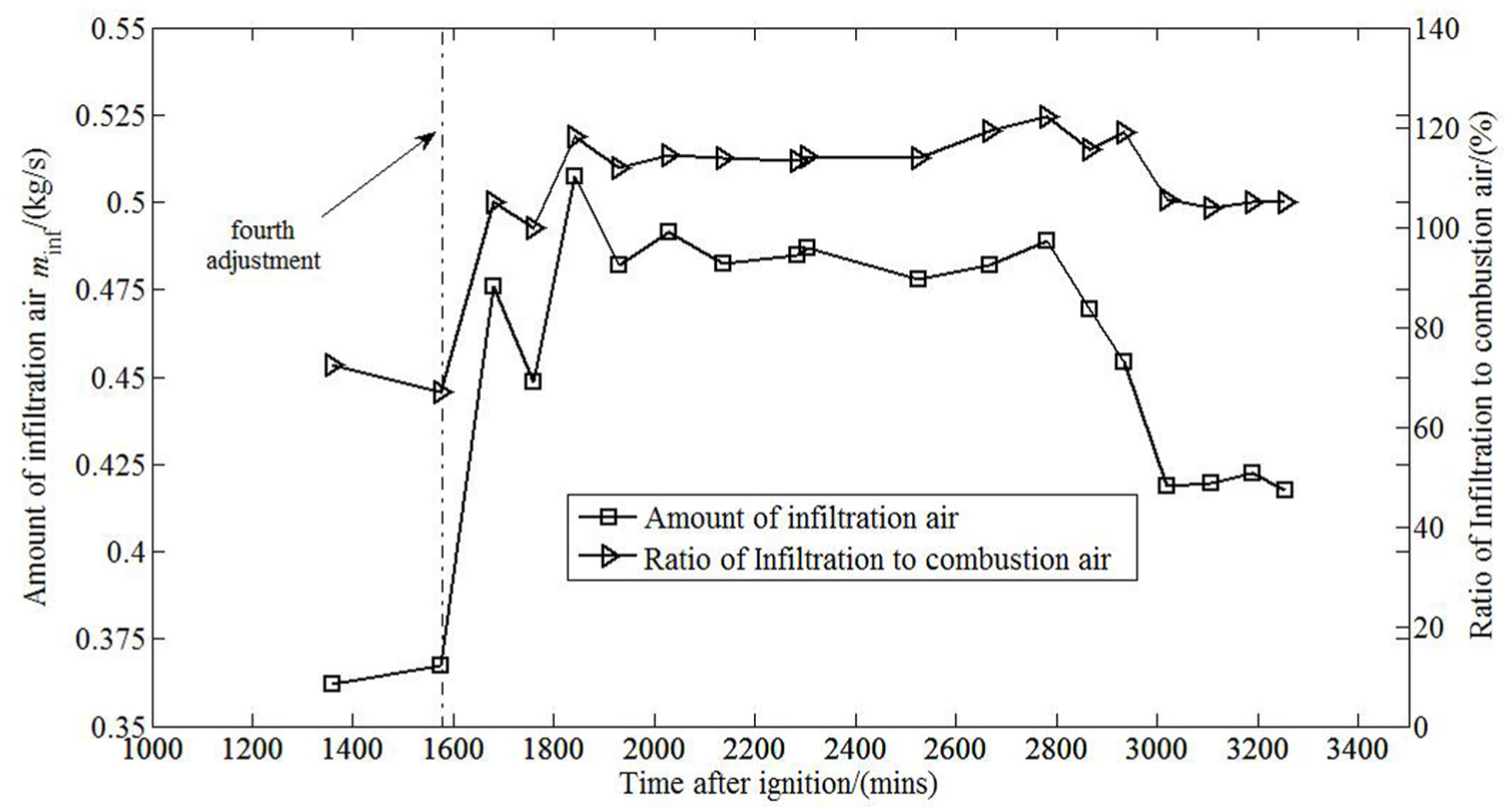
Infiltration of cold air at venting exits.
It should be noted that infiltration air decreased the temperature of flue gas entering air preheater dramatically, which means a visible waste to be immediately improved. If the infiltration could be reduced to zero by some means, the flue gas at the inlet of the preheater would keep almost the same as Tf1 (or Tf2), about 1200°C. The combustion air then could be heated to 340°C even with the present air preheater, and the thermal efficiency could be increased by 11%.
Heat loss of flue gas
As shown in Figure 6, flue gas leaving No. 1 kiln mixed with cooling air from No. 2 kiln. The mixture came into air preheater to recover some amount of energy and then vented into chimney. The heat loss carried by mixture venting into the chimney can be calculated according to equation (10)

where
The total mass flow rate of air delivered to No. 1 kiln and No. 2 kiln, m1 + m2, was calculated according to measured velocity (FRa) and temperature (Ta). So mass flow rate of air delivered to No. 2 kiln could be determined. Finally, the component balance would give detailed components of mixture vented into the chimney, which was used to calculate specific heat
The total energy carried by mixture venting into the chimney turned out to be 7.3224 × 10⁷ kJ during the heating period (from ignition to shutoff), or equivalent to 2125 N m3 of natural gas. If the flue gas mixture could be cooled down to 200°C, 872 N m3 of natural gas would be recovered. The efficiency could be increased by 5.5%.
Air preheater effectiveness analysis
As a heat exchanger, the media of air preheater at both sides are high-temperature flue gas mixture and air. The effectiveness can be defined as the ratio of temperature difference between inlet air and outlet air to that between flue gas inlet and air inlet, namely
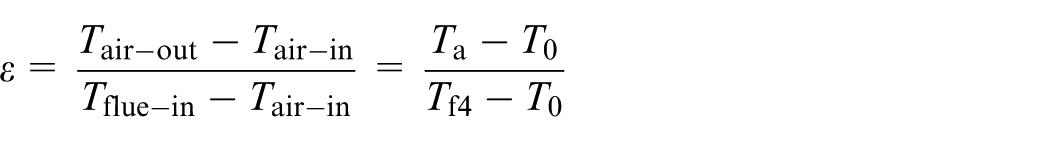
The calculated effectiveness of air preheater is shown in Figure 11. The averaged effectiveness lower than 30% revealed its poor performance. If the effectiveness could be increased to 50% and the averaged flue gas inlet temperature was somehow taken as 700°C, the preheated air could reach about 360°C. This means the efficiency of the kiln could be raised by about 15%. On the other hand, the heating period could be shortened due to increased flame temperature resulting from increased preheated air temperature.

Effectiveness of air preheater and related temperatures.
Conclusion
If measured in terms of energy balance either during the whole heating period or within a specific period, the thermal efficiency of kiln is quite low, namely, as low as 13%–15%.
The heat carried by flue gas accounted for 50% of the total output. This can be attributed to the increasingly poor heat transfer within the kiln. When the temperature of processed refractory was gradually increased with time, the temperature difference between hot gas and the processed refractory could not be increased effectively. Because the temperature of preheated air was not able to be increased due to poor performance of air preheater, the temperature of flame and hot gases within the kiln could not keep the required increasing pace. On one hand, heat transfer from hot gases to processed refractory gradually decreased. On the other hand, the required heating period was prolonged to achieve the required temperature. What’s more because the volume of the preheated air expands as the temperature increases, so that the oxygen content per unit volume is decreased, while the supply of natural gas is not changed, the combustion efficiency is not good, resulting in natural gas will not be incomplete burned.
Flue gas analysis revealed that serious cold air infiltration occurred at the spacing between the venting exits and the entrance of the venting tunnel. The infiltration amount was found to be increased with increasing gas temperatures within the kiln. Large amount of cold air which was entrained radically decreased the temperature of flue gas entering air preheater, to further degrade the performance of air preheater. In addition, combustion air was found to be not uniformly distributed within kiln spatially. If combustion efficiency was anticipated, the mixing process of the burners has to be optimized.
If the flue gas mixture could be cooled down to 200°C, 872 N m3 of natural gas would be recovered. The efficiency could be increased by 5.5%; if the infiltration could be reduced to zero by some means, the thermal efficiency could be increased by 11%; if the effectiveness of air preheater could be increased to 50%, the efficiency of the kiln could be raised by about 15%, and the energy conservation potential is tremendous.
Footnotes
Academic Editor: Lin-Shu Wang
Declaration of conflicting interests
The author(s) declared no potential conflicts of interest with respect to the research, authorship, and/or publication of this article.
Funding
The author(s) received no financial support for the research, authorship, and/or publication of this article.