
Abstract
Model predictive control on a highly coupled open-frame remotely operated vehicle system subjected to uncertain disturbances has always been a challenge. A decentralized model predictive control uses a design scaling to balance the interactions between the loops to achieve a block diagonal dominant remotely operated vehicle model is used. The numerical stability of the model predictive control algorithm improves despite the sensitivity of the control parameters on the output performance. The model predictive control gives a better two-error norm performance and more tuning options to control the velocity and position output as compared to other design scaling methods and other controllers such as proportional–integral–derivative, fuzzy logic, sliding mode, and proportional–integral plus proportional cascaded control when subjected to underwater current disturbance.
Keywords
Introduction
Model predictive control (MPC) uses an explicit and a separately identifiable model for control. The concept of MPC algorithm is based on the moving horizon approach where the control action is computed to obtain the desired performance over a finite time horizon under uncertainties and constraints. 1 The use of the constraints clearly distinguishes MPC from other control methods such as neural network–based approach,2–8 leading to a more reliable controller and tighter control with no requirement on training data. However, the heavy online computational burden 9 and numerical condition of the control algorithm are the main obstacles in the application of MPC. A large computational delay and global minimum or even local minimum cannot be achieved due to time constraint in each time horizon. One approach is to obtain a closed-form optimal MPC10,11 to circumvent the computational issue. However, it is hard to predict the system output over a long horizon since the output order is limited by the relative degree of a nonlinear model, and it can be quite unstable12–14 for a large relative degree. With the derivatives of the control as an addition state, the robustness of the MPC under the model complexity such as highly coupled in states 15 and uncertainty when subjected to external disturbances pose an even greater challenge to the applied control community.
In the current literature, most of the applications of MPC were applied on the following systems such as ALSTOM gasifier control, 16 pH control, 17 obstacle avoidance for land robot, 18 pneumatic brake system, 19 trailing edge flapping on wind turbine blade, 20 power converters, 21 solar energy system 22 and induction motor, 23 and few autonomous underwater vehicles (AUVs).24,25 The robust stability due to disturbances and the model uncertainties on the AUV were largely studied. However, the model used for the AUV control is quite decoupled in states due to its streamlined body design. The MPC on a highly coupled in states model such as a remotely operated vehicle (ROV) has not been studied. The inherent ROV’s model uncertainties due to hydrodynamic parameters, inertial nonlinearity, and coupling between the degrees of freedoms (DoFs) are worsened by the external disturbances due to underwater current. Applying the conventional MPC on this class of underwater vehicle creates a numerical stability issue on the control algorithm.
To overcome the numerical stability problem of MPC on a highly coupled ROV model, we propose the use of non-unity permutation matrices on ROV model before MPC system design to numerically condition and decentralize the model. It results in a block decentralized model for MPC. This article gives new simulation results of MPC laws and robust stability for a hover-capable ROV designed by Nanyang Technological University (NTU) in Singapore. The application of the MPC with two non-unity permutation matrices on a highly coupled system such as ROV model leads to a more decentralized predictive control system architecture design which makes the overall approach more decentralized.
The remainder of this article is organized as follows. Section “ROV model descriptions” gives the details of ROV model. Section “Block diagonal dominance model for ROV” describes the block diagonal dominance model for ROV. It is followed by the MPC design methodology in section “Decentralized MPC.” Section “Robust performance analysis” includes the robust performance analysis of ROV and comparison study of different controllers. Finally, the article ends with a conclusion.
ROV model descriptions
The ROV model used for control is the Robotics Research Centre (RRC) ROV26,27 designed by NTU. The ROV plant model is quite coupled in the velocity states, namely, surge, sway, heave, roll, pitch, and yaw velocity in the dynamics equation. The RRC ROV (Figure 1) was designed to perform underwater pipeline inspections such as locating pipe leakages or cracks. The twin “eyeball” ROV depicted in Figure 1 has an open-frame structure. It measured 1 m long, 0.9 m wide, and 0.9 m high. It has a dry mass of 115 kg and a current operating depth of 100 m. The RRC ROV has only four thrusters to control 6 DoFs (i.e. surge, sway, heave, roll, pitch, and yaw velocity) and has a high level of cross coupling between the states. The roll and pitch motions are passive as the metacentric height is sufficient to provide adequate static stability. A brief description of the component layout of the RRC ROV is given:
Four thrusters, each providing up to 70 N of thrust;
Two cylindrical floats with four balancing steel weight;
Main Pod (Pod 1) and sensors with navigational Pod (Pod 2);
Two halogen lamps, an altimeter (for depth measurement), and a Doppler velocity log (for velocity measurement).

Before the ROV modeling, the following assumptions were made:
ROV is a rigid body and is fully submerged once in the water;
Water is assumed to be ideal fluid that is incompressible, inviscid, and irrotational;
ROV is slow moving during pipeline inspection;
The earth-fixed frame of reference is inertial;
Disturbance due to wave is neglected as it is designed for submerged operation;
Tether dynamics attached to ROV is not modeled.
The motion of a rigid body on the body-fixed reference frame at the origin (Figure 1) is given by the equation 28

where
The mass inertia matrix given in equation (1) can be written as follows

where xG, yG, and zG are the coordinates of the center of gravity and m is the mass of the ROV. Here Ix, Iy, and Iz are the moments of inertia about the principal axes of the ROV, and Ixy = Iyx, Ixz = Izx, and Iyz = Izy are the products of the inertia. Here, the parameters used in equation (2) are as follows:
The Coriolis and centripetal terms describing the angular motion of ROV can be expressed as follows

with


The nonlinear ROV dynamics equation and the kinematic equation can be expressed as follows


where
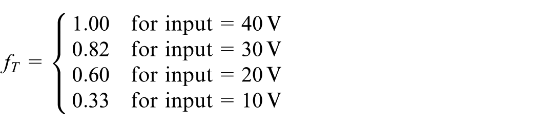
The dynamic model of the thruster was obtained experimentally using the test rig.26,27 A simplified first-order thruster model was obtained as follows

where
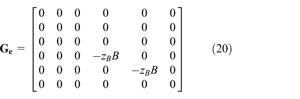
As the ROV was designed to be neutrally buoyant by adding an additional float or balancing mass, the gravitational force due to the ROV weight can be made equal to the buoyancy force,

where
Since the ROV is symmetric about the XZ plane and close to symmetric about YZ plane, we assumed that the motions in surge, sway, pitch, and yaw are decoupled. Although it is not completely symmetric about the XY plane, the ROV is operating at a relatively low speed in which the coupling effects 28 can be negligible. With this assumption, the damping matrix in equation (6) becomes

For most low-speed maneuvering tasks, the off-diagonal terms in the added mass matrix are neglected
28
in most applications.
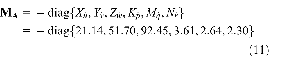
Since the off-diagonal elements in

A series of experimental tests were performed to verify the hydrodynamic damping and added mass coefficients. The complete details of the numerical modeling, simulation, and experimental tests on the RRC ROV model can be found in Chin et al.26,27
Linear ROV subsystem model
A linearized model of the ROV operating at station-keeping condition is obtained by linearizing the nonlinear ROV in equations (6) and (7) about an equilibrium point


For brevity, the linearization procedure using Taylor series will be omitted. Defining
It can be written in abbreviated form as follows

During the maneuvering in a vertical plane, the steady-state linear and angular components are assumed as vo = po = qo = ro = 0 and the equilibrium point is defined by the zero roll and pitch angles, that is ϕo = θo = 0. Hence, the time-varying matrices for the vertical plane motion


If we assumed that

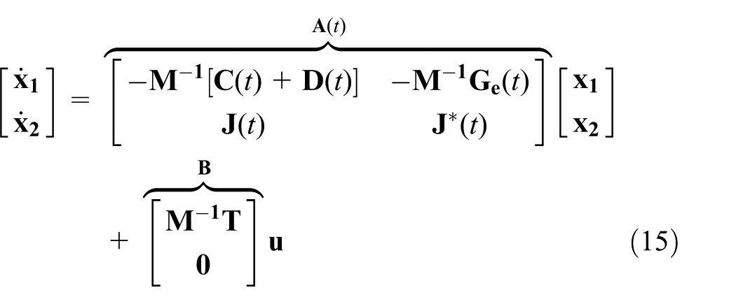
Consequently, the linear time-invariant model for both velocity

where
During the station keeping, the controller is tasked to maintain the vehicle about the equilibrium position. The linearization about the equilibrium point

where

where
Block diagonal dominance model for ROV
Before control system design, the inherent properties such as open-loop stability, right half plane (RHP) zero, and system interactions are examined. Since the RRC ROV is unlikely to exceed
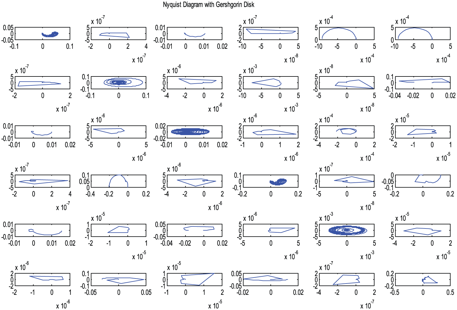
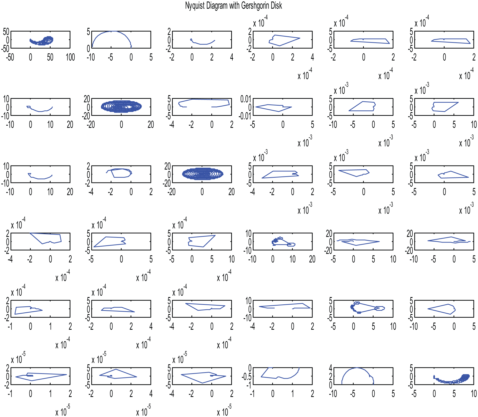
Direct Nyquist Array (DNA) with Gershgorin disks before scaling.
The corresponding row and column dominance measure (i.e. the sum of the off-diagonal terms in each row or column over the absolute value of the transfer function evaluated at each frequency) shows that the magnitudes are indeed not small. The two-norm values are approximately 4.9 × 10³ and 3.3 × 10³ for the row and column dominance, respectively. It further confirmed that the RRC ROV is highly coupled in motions. Also, the singular value and condition number at different frequencies plot shows that the ROV is highly coupled in motions. As shown in Figure 3, there are many peaks, in particularly at approximately 49.95 rad/s. A design scaling is therefore required to reduce the coupling and to improve the numerical condition via a more decentralized structure before MPC layout.
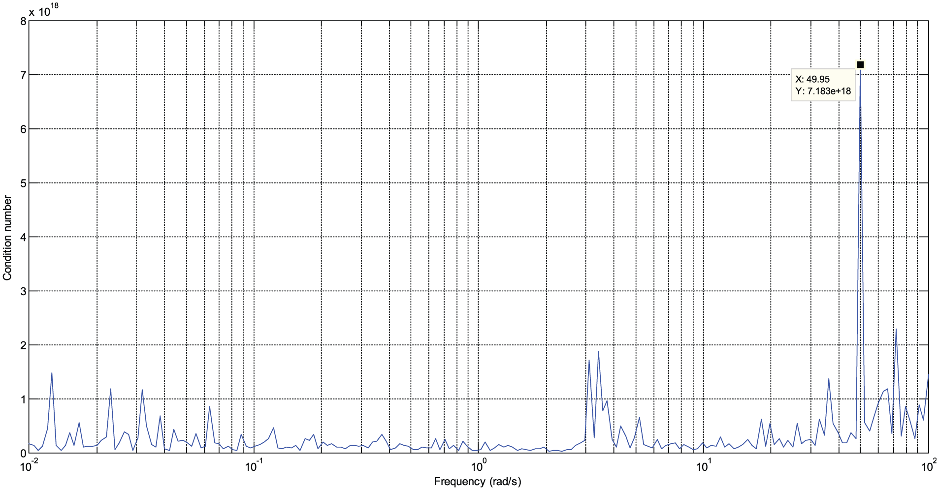
Condition number at different frequencies.
Various design scaling methods such as Edmunds 12 scaling, one-norm, and Perron–Frobenius (PF) scaling are used. The scaling frequency at 10 rad/s is chosen due to its lowest condition number among the scaling methods. The outputs are a non-unity diagonal pre- and post-compensator with different values. The Edmunds scaling algorithm (see Appendix 1 for the algorithm written in MATLAB) provides both scaling and input–output pairings as seen in the non-unity permutation matrices. Both the columns and rows are now reordered into the following sequence: surge, pitch, heave, yaw, sway, and roll


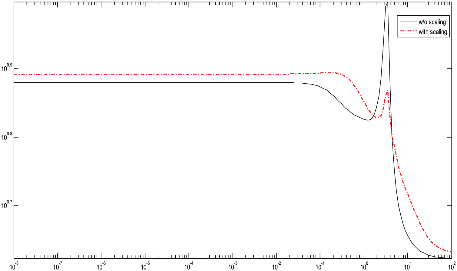
The row dominance ratio of each scaling method is compared. It was found that the PF scaling (row dominance ratio, 159; column dominance ratio, 334) has the smaller dominance ratio as compared to the Edmunds scaling (row dominance ratio, 323; column dominance ratio, 497) and one-norm (row dominance ratio, 323; column dominance ratio, 497) scaling method. However, the one-norm design scaling gives the lowest condition number (or less ill-conditioned) over the frequencies as shown in Figure 4. This is also reflected in the less concentration of Gershgorin disks at the origin of the plot in Figure 5.

Condition number at different frequencies.
Direct Nyquist Array with Gershgorin disks after one-norm scaling.
However, the transfer function matrix (TFM) of the ROV is unlikely to be made diagonal dominant by this simple diagonal constant scaling matrix. It can be verified in Figure 6 as the gain in dB over the frequencies of interest are all greater than 6 dB.

Perron–Frobenius eigenvalues of ROV system.
The Edmunds scaling using the non-unity permutation matrices is therefore chosen. It helps to numerically condition and reduces the interactions between the input-to-output interactions as it is not always possible to have a clear diagonal dominance at each row or column. The proof of the numerical stability can be seen in Edmunds.
12
As shown in Figure 7, the ROV system can be grouped into two blocks of

where superscript

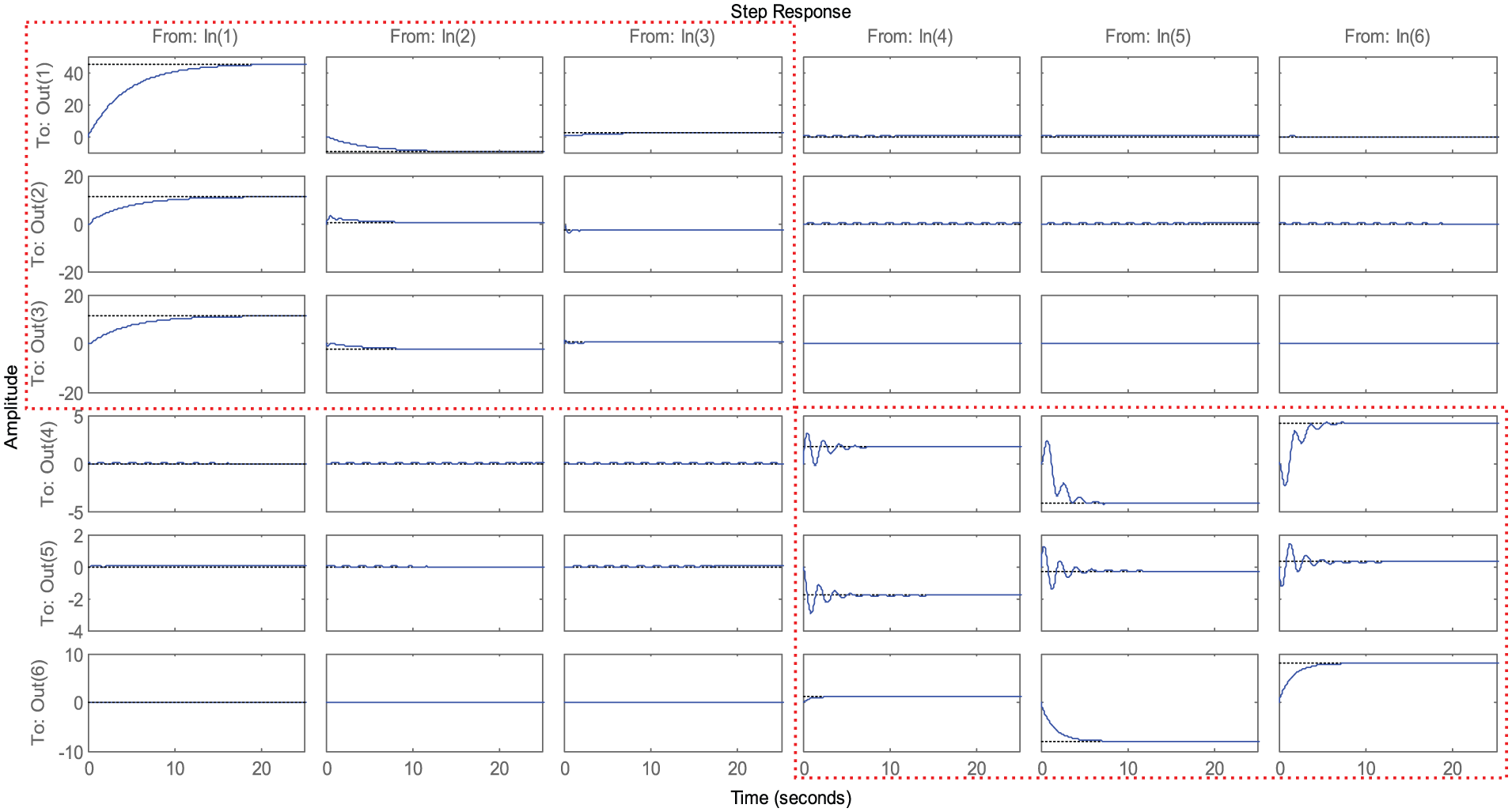
Decoupled step response.
To verify that the RRC ROV system is now block diagonal dominant, Figure 8 shows the block dominance measure of the system before and after the Edmunds scaling using

Block diagonal dominance measure before (left) and after (right) Edmunds scaling.
After achieving a better numerically conditioned system, another important part of a multivariable design is the input–output pairing. Applying the relative gain array (RGA) to the decentralized ROV system at the steady-state condition as

By evaluating the RGA number across the frequencies of interest after the row permutation (by Edmunds scaling), there is a slight decrease in the RGA number after ordering across the frequencies as seen in Figure 9. It implies that the selected I/O pairs have an effect on the diagonal dominance of the system. A lower RGA number corresponds to lower condition number of the ROV system. It is a “good” feature of the control system design.
RGA number of ROV.
The proposed Edmunds scaling algorithm on the TFM sets all the row and column sums to unity using simple iterative steps. The algorithm equalizes and maximizes the geometric mean of the row dominance and geometric mean of the column dominance for given inputs and outputs. It improves the numerical stability in MPC system design where the solution of the algebraic Riccati equation is needed. Also, the design scaling makes the individual loops more independent by balancing the interactions between the loops. As a result, the scaled state-space model of ROV becomes


where
Decentralized MPC
In the research literature, MPC is formulated in state space. The MPC is obtained by minimizing the cost function by application of the quadratic programming algorithms
14
and the relevant references cited in this text. The model of the ROV is described by the linear difference equations (24) and (25). As the input


With a new state vector


where
The information of the state vector at a time

The predicted future state at time

where


where
The predicted output at a time

where


The optimal

that minimizes

The optimal control signal is written as follows

The first term is the derivative of the input state

where
The control signal computation is carried out by simply approximating the derivative
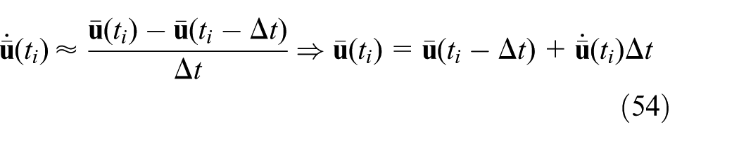
The actual control signal

The optimal solution with the exponentially weighted cost function is identical to the original optimal solution without exponential weighting when the prediction horizon is sufficiently large. However, without modification on the pair of weight matrices
The control amplitude constraints for the state-space model at a time t can be written in the form where

The constraints on

where
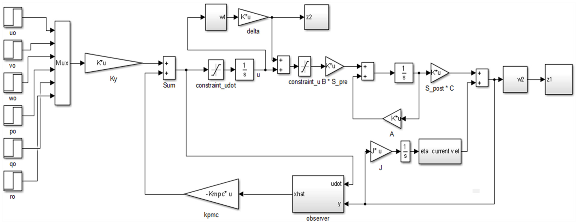
The implementation of MPC law also requires direct measurement of all elements in

where
In summary, the steps to design the decentralized MPC with Edmunds scaling are as follows:
Determine the non-unity permutation matrices (
Form the augmented matrix for MPC using Edmunds scaling in equations (39) and (40);
Set parameters for continuous MPC-time scaling parameter
Solve Riccati equation for
Define constraint
Solve MPC for
Compute observer gain matrix,
Compute the derivative state-feedback gain for
Compute the state feedback gain
Plot
Robust performance analysis
As the ROV is subjected to uncertainties, its robustness performance needs to be examined. The ROV subjected to changing underwater current effect will be simulated. It is followed by comparing the results to various scaling methods. For completeness, the proposed MPC will be compared with different types of controllers under a fixed and varying controller gains.
Robust analysis on ROV subjected to underwater current
The robustness analysis of the decentralized MPC on the ROV is performed. The uncertain perturbations are formed in a block diagonal matrix of stable perturbations,

Control system structure for uncertain ROV system.
The uncertain closed-loop transfer function is related to

As shown in Figure 10, the ROV closed-loop system has multiplicative input uncertainty,

The partition of

Equation (59) becomes

The weighting function is used to shape the sensitivity of the closed-loop system,


Weighting function for output performance and input.
For robust stability, the following conditions for the ROV in the uncertainty set need to satisfy for robust performance:

Sensitivity plot of
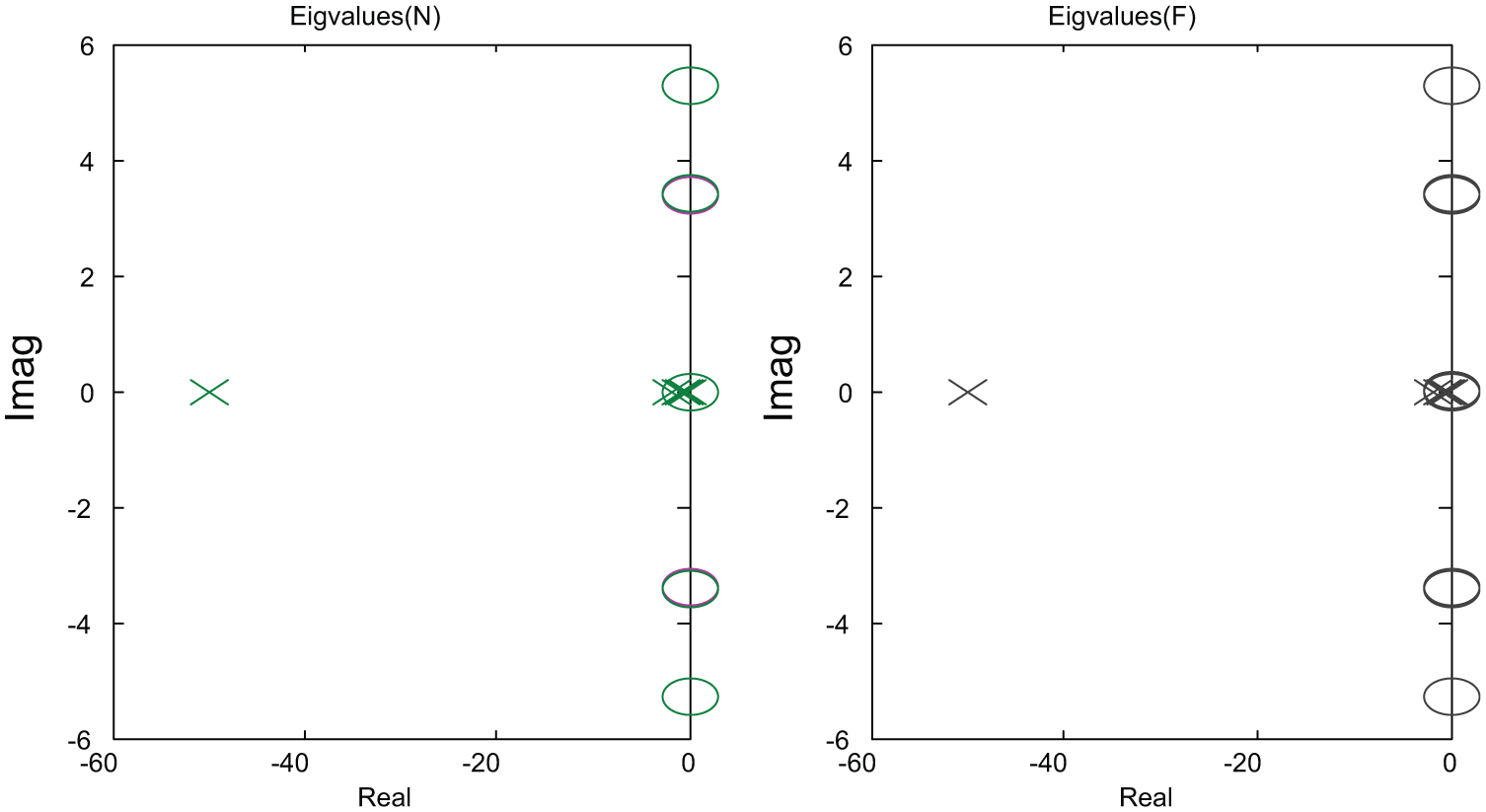
Pole and zeros of closed-loop ROV system.
As shown in Figure 13, all eigenvalues (including
The current velocity is included as a relative velocity,


where αc is the angle of attack and βc is the sideslip angle.
During the simulation, both angles of attack and sideslip angle are set to 45°. The current speed was incremented by 1 m/s until 10 m/s (for testing the robustness of the system). However, these settings can be adjusted to reflect the actual current experienced by the ROV. As shown in Figure 14, the H-infinity norm of the linear velocity increases with the sea current. The increase in the output linear velocities begins gradually with less impact on the angular velocities (as observed from the smaller magnitude in the H-infinity norm). The ROV system is quite robustly stable under the underwater current disturbances for underwater current not more than 3 m/s. As observed in Figure 14, the hinf-norm increases exponentially after 3 m/s.
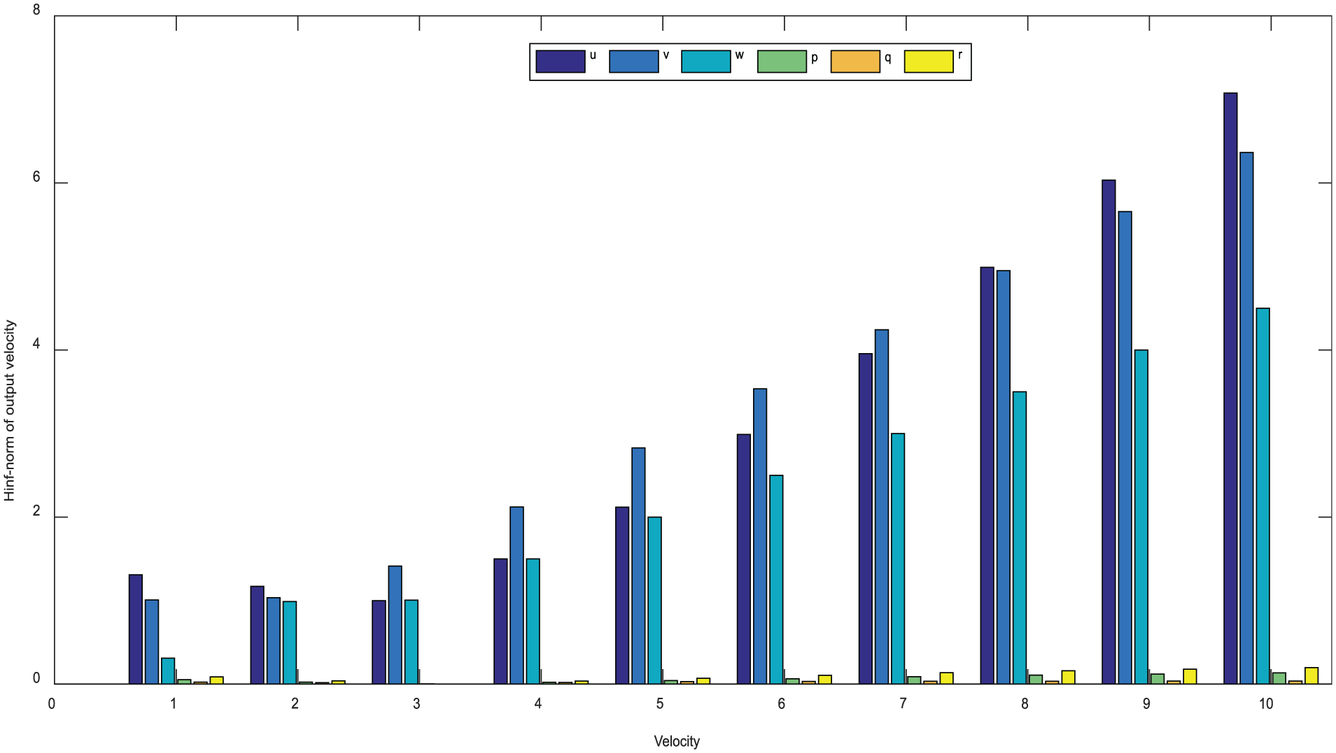
H-infinity norm of output velocity (subjected to underwater current).
Robust analysis on ROV using various scaling methods
The time response simulation of the decentralized MPC on the ROV was performed under the MATLAB/Simulink™ environment. The parameters used in the scaling methods and MPC are varied to study the robust performance of each method. From the simulation results, the parameters employed in the simulation were determined through multiple trials till the system becomes unstable. From the previous simulations, the control horizon
As observed, the output responses are constant with higher
One-norm scaling:
Edmunds scaling:
PF scaling:
Without scaling:
Figures 15–17 show the comparison results of using different scaling methods when the ROV is moving at

Velocity time response of various design scaling methods.

Control input rate of various design scaling methods.

Control input of various design scaling methods.
All scaling methods exhibit quite a high sway velocity (but within the constraint) as compared to surge direction. However, as the vehicle moves diagonally to the set point, there is a higher sway position response as compared to the surge direction. Fortunately, the remaining DoFs are not excited as the ROV system matrix is now less coupled. It shows that the ROV system has a faster response to the desired set point target under the input constraints. If the ROV encountered a significant disturbance in the inputs, the maximum thrust could help the ROV to maintain its closed-loop stability and reject the disturbance quickly.
The simulated results provide evidence that the decentralized model predictive controller using Edmunds design scaling is capable to control both surge and sway velocities to the desired set point. The roll, pitch, and yaw rate are quite small in the design scaling methods.
Comparisons with different controllers under fixed control parameters
MPC has not been applied to a highly coupled open-frame ROV system subjected to uncertain disturbance. The conventional control schemes such as proportional–integral–derivative (PID),
29
fuzzy logic,
30
sliding-mode control (SMC),
31
and proportional–integral plus proportional (P-PI) cascaded control
26
are compared with the proposed decentralized MPC. Note that this is not the complete list of controllers used in the current literature. However, it serves to compare with the proposed MPC. For consistency, the same input commands,
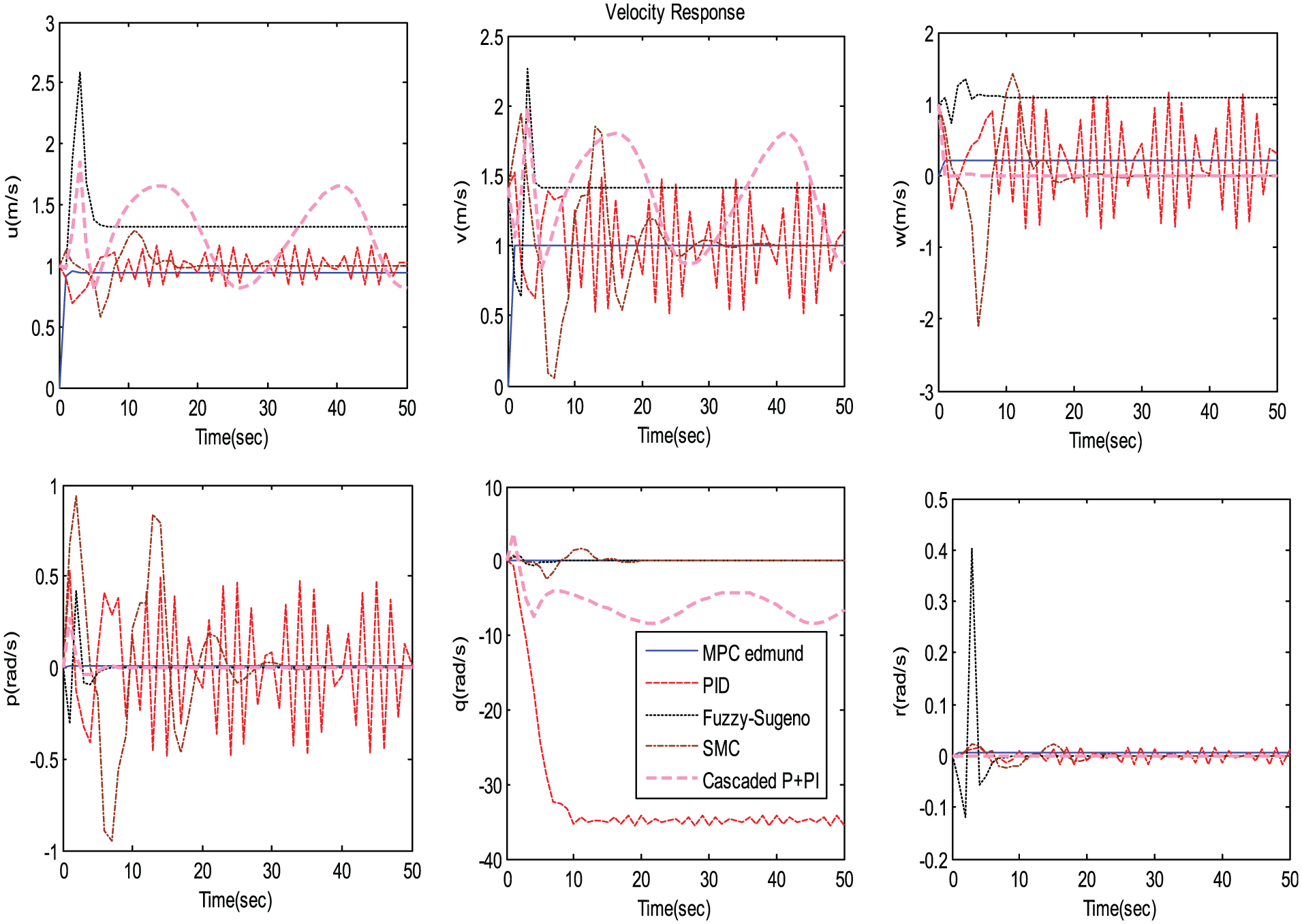
Proposed decentralized MPC comparisons with other control schemes.
On the other hand, the cascaded control scheme with PI-P gives less oscillatory behavior. However, the overshoot is quite significant as compared to the conventional PID single-loop control structure. Fuzzy logic control exhibits less oscillatory motion but exhibits steady-state error of approximately 50% with oscillatory in the angular velocities and a prominent response of 1 m/s in heave motion. SMC has demonstrated quite a good steady-state value. It can attenuate the disturbance with a small steady-state error. Finally, the proposed decentralized MPC exhibits good overall response and is capable of achieving a good steady-state value under the disturbances as compared to the controllers. As observed, the roll and yaw motion are quite stable for most control schemes. As shown in Table 1, the proposed MPC controller with a decentralized scheme using Edmunds scaling performs slightly better (as seen in the two-norm and infinity norm of the velocity response) than other controllers.
Two and infinity norm comparison between the controller’s velocity response.
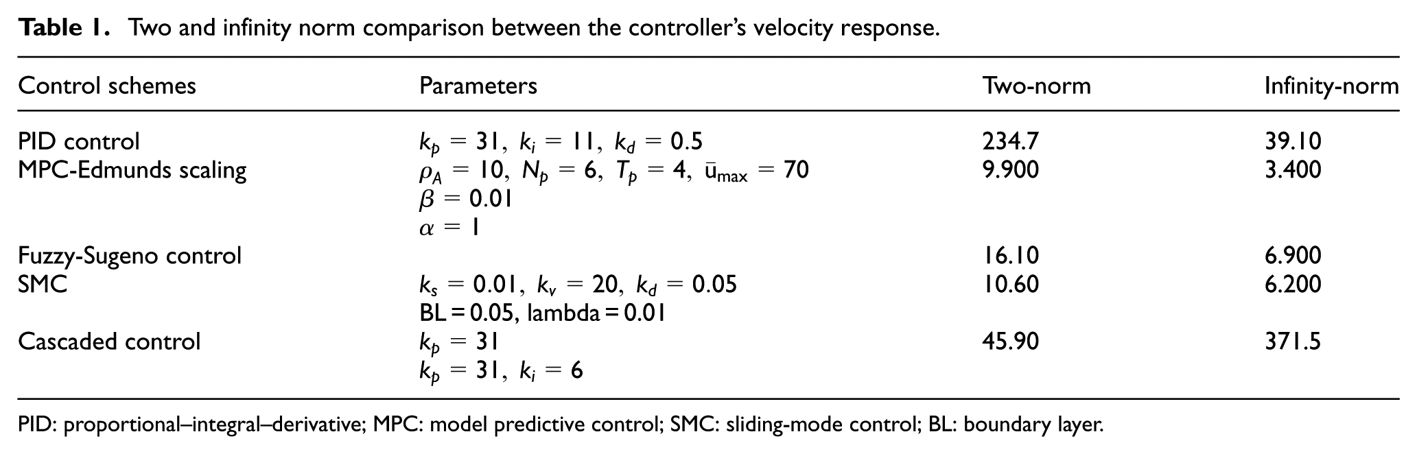
PID: proportional–integral–derivative; MPC: model predictive control; SMC: sliding-mode control; BL: boundary layer.
Comparisons with different controllers under varying control parameters
The effects of different controller gains on the ROV’s output velocity responses are examined. We reviewed the change in only one controller gain by a fixed increment at any one time. The two-norm errors of the velocity outputs are then computed. The decentralized MPC using the Edmunds scaling is first examined. Initially,

Two-norm error of proposed decentralized MPC comparisons at different control parameters.
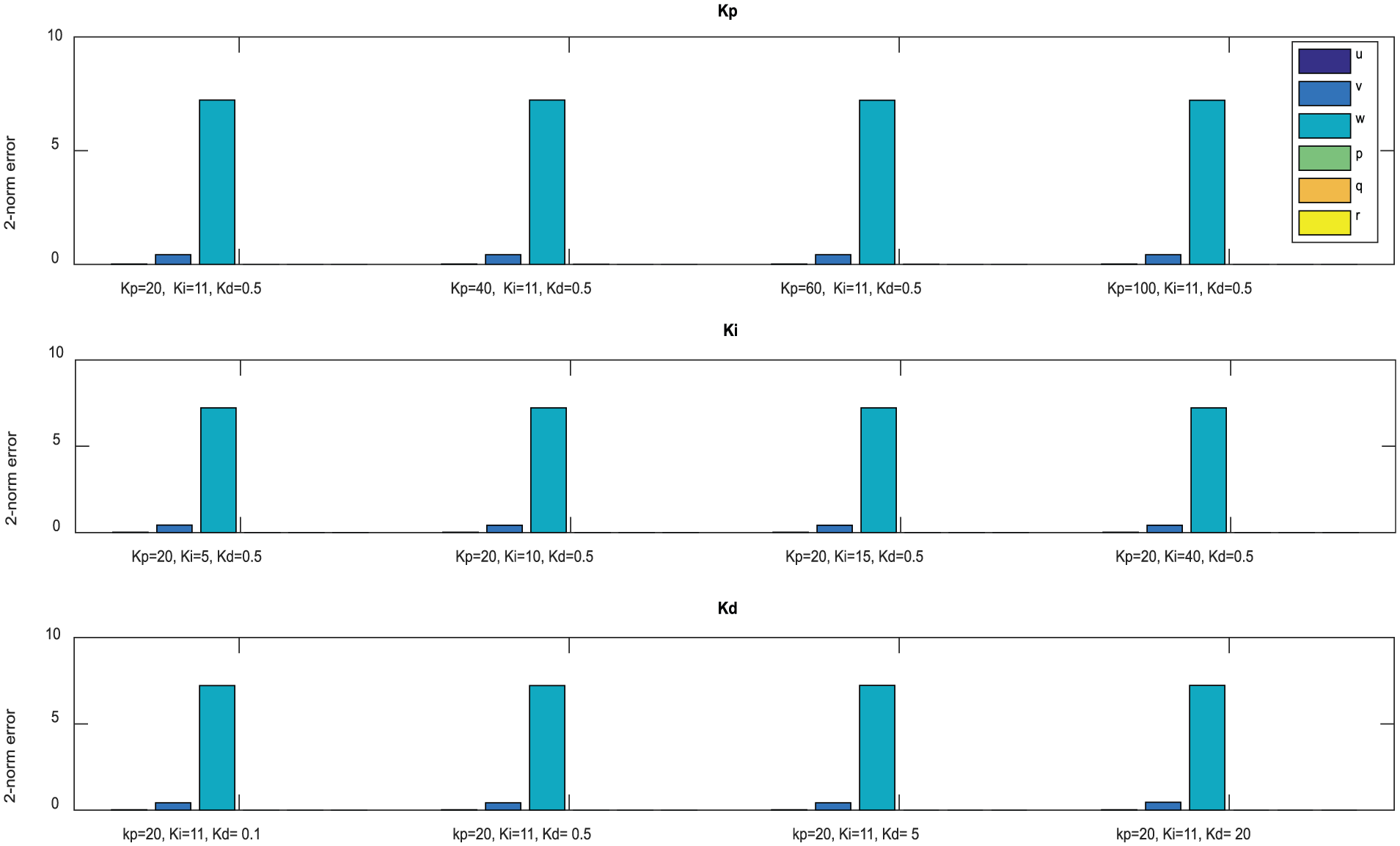
Two-norm error of PID controller at different control parameters.

Two-norm error of SMC at different control parameters.

Two-norm error of P-PI cascaded control at various control parameters.
Conclusion
The robust decentralized MPC of a ROV is proposed. The proposed Edmunds design scaling algorithm on the TFM equalizes and maximizes the geometric mean of the row dominance for given inputs and outputs. The design scaling makes the individual control loops more independent, hence able to achieve a decentralized ROV model for MPC. The simulation results show that the decentralized MPC using Edmunds scaling exhibits a better performance as compared to other design scaling methods.
The proposed decentralized MPC behaves quite well in the velocity response as compared with PID, fuzzy logic, SMC, and P-PI cascaded control scheme. The simulated results have shown some evidences that the decentralized model predictive controller using Edmunds design scaling is capable of controlling the ROV. From the results, the decentralized MPC algorithm can be implemented with a less numerical error. Although the proposed decentralized MPC with Edmunds scaling is quite sensitive to some control parameters, it offers more options to tune the ROV’s output performance to achieve a lower two-norm error.
Future works will include using a time-varying nonlinear ROV model subjected to parametric and multiple uncertain external disturbances. Comparisons with more controllers such as adaptive neural network control will be performed on ROV system.
Footnotes
Appendix 1
Acknowledgements
The authors would like to thank Newcastle University in the United Kingdom and Nanyang Technological University (in Singapore) for providing information and assistance and the reviewers for their valuable comments.
Academic Editor: Bin Xu
Declaration of conflicting interests
The author(s) declared no potential conflicts of interest with respect to the research, authorship, and/or publication of this article.
Funding
The author(s) received no financial support for the research, authorship, and/or publication of this article.