
Abstract
Because of the high-speed rotating impeller and the asymmetry volute, the flow parameters are strongly nonlinear in the screw centrifugal pump runner, in which the flow is multi-scale irregular and complex; moreover, the solid–liquid two-phase flow exacerbated the degree of nonlinear. To analyze the mechanism of solid–liquid two-phase flow and the evolution of the vortex in screw centrifugal pump, the model of the large- and meso-scale vortex evolution when the solid–liquid two-phase flow layered with the buoyancy effect is established, the flow structure and the change regulation of inner flow are revealed in the screw centrifugal pump, by the means of theoretical study of the inner flow states of the screw centrifugal pump, and the calculation of the internal flow field numerical simulation was performed. The research shows that the isodensity surface and isobaric surface are oblique which lead to the change in the vorticity; with both the fluid viscosity and the baroclinicity, the working vortex maintains an orderly flow form in time and space; the form of the vortex is mainly affected by the forces of fluid field, the vortex constantly reshapes the flow structure, the low-pressure areas form the positive vortex, while high-pressure areas are inclined to forming the reverse vortex, both the positive and reverse vortices always appear in pairs, which make the fluid take on the next states continuously; it is the difference of solid and liquid proportion in the solid–liquid two-phase flow that results in the phenomenon in which the flow tends to form different concentrations and stratifications, especially in rotating machinery; these phenomena are more common. With the effect of the rotating machinery impeller, the flow field becomes the flow with the vorticity, namely, forming the rotational flow, as well as the velocity difference between solid and liquid in the solid–liquid two-phase flow, and leads to that the fluid machinery internal velocity gradient and pressure gradient change is considerably great, which induces and motivates the generation and evolution of the vortex further.
Keywords
Introduction
The screw centrifugal pump serves as a kind of solid–liquid two-phase flow pump with special structure, it integrates the advantages of the screw pump and the centrifugal pump, and its unique structure can give full play to the advantages of the two. Compared with other impurity pump, the screw centrifugal pump has the pretty outstanding excellence of non-clogging performance, self-priming performance, adjusting performance and anti-cavitation performance, and has the advantages of no overload, high efficiency, high efficiency area, and so on.1,2
The imbalance of flow, which is an important feature of the solid–liquid two-phase flow, behaves in two forms, the vortex and stratification in the screw centrifugal pump, which reflects the irregular function relationship between the turbulent flow velocity, pressure, and other physical parameters in the time and space, as a matter of fact that is the diffusion of fluid mass and energy in the time and space with the mechanical action of the impeller.3,4 When the turbulence develops to a certain stage, the flow will stimulate and engender the phenomenon in the fluid machinery, such as cavitation, vortex, secondary flow, counter-flow, boundary layer separation, wake flow, and other performance that will damage the fluid machinery. Therefore, it is very necessary, especially for the solid–liquid two-phase pump, to diagnosis the flow structure of the fluid field by analyzing the internal flow of the screw centrifugal pump. In order to understand the vortex structure further, the evolution of the fluid vortex structure is analyzed in the rotating fluid machinery, and the model of the vortex structure generation, diffusion, and response is established as follows.
Theoretical analysis of the viscous fluid flow model
The rotation of the viscous fluid
The viscous fluid flow is rotational, which is one of the dynamic characteristics of the viscous fluid, next apply the apagoge to prove.
The incompressible viscous fluid continuity equation and momentum equation are shown in equation (1)

where,
Since the viscous flow boundary condition is no-slip condition on the surface of solid wall, the flow velocity

Solving the second-order partial differential equation in equation (1) as equation (2) has two boundary conditions, the solution can be obtained.
If assumed that the vorticity in the viscous flow is zero, scilicet

Thus, equation (3) is a first-order partial differential equation, and one must be superfluous in the two boundary conditions of equation (2); it is impossible to meet Euler equation of non-viscous fluid and the viscous no-slip flow condition at same time. Therefore, the viscous fluid flow must be rotational.
The dynamic equations of the rotating fluid
The vorticity field has equal angular velocity

where subscript R denotes a rotating frame of reference physical quantities and I represents inertial frame of reference physical quantities in equation (4). Here,
In uniform rotation systems,
Using equation (4) and the N–S (Navier–Stokes) equation for incompressible fluids, one can obtain

Equation (5) is the dynamic equation of the uniform rotating reference system (rotating machinery relative reference system).
Compared with the N–S equation for incompressible fluids, the dynamic equation of the uniform rotating reference system has two more terms as follows:
The Coriolis force acting on the fluid micelles of the unit mass;
The centrifugal force acting on the fluid micelles of the unit mass.
In equation (6),
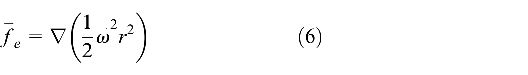
Therefore, equation (5) can be written with the form as follows

The analysis of the vortex generation in the pump impeller domain
Figure 1 shows the rotating coordinate system of the impeller region since the angular speed component

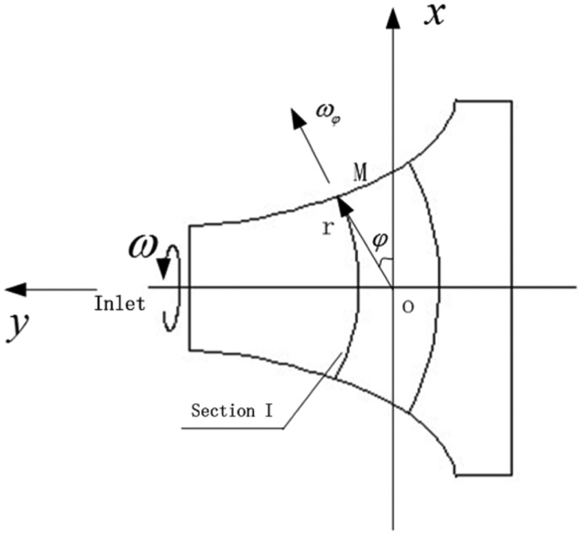
The rotating coordinate system of the impeller domain.
The Coriolis force acting on any radial section I is shown in Figure 2, where the component is
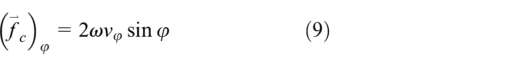

The diagrammatic sketch of the Coriolis and centrifugal forces on section I.
The direction of
Similarly, as the fluid surrounding the vortex flows around the vortex with the impeller driven, these areas near the rim form the high-pressure zones and generate the phenomena that the fluid flows toward the surrounding areas; also, with the Coriolis and centrifugal forces working together, these areas form the reverse vortex, as shown in Figure 2. That is to say, the vortex is mainly generated by the action of the fluid force field, which remodels the fluid flowing structure uninterruptedly, low-pressure zones are inclined to forming positive vortex, high-pressure zones are apt to forming reverse vortex, while both positive and reverse vortices always turn out in pairs (Figure 3), in this way, the fluid can act as the next behavior.
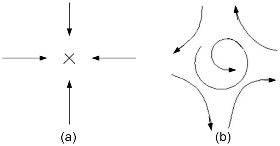
The forms of the vortex: (a) the positive vortex and (b) the reverse vortex.
The influence on the vortex generation with the tratified fluid buoyancy effect
In the screw centrifugal pump, especially when it transports the solid–liquid two-phase fluid, with the action of the impeller, combined with differences in the proportion of solid and liquid, the two-phase fluid presents the phenomenon of stratified strongly, and its concentration generates the gradients with the emergence of the impeller position different, thus assume that

In equation (10), Cv is the reference concentration, usually is the average concentration;
Namely, there is

Suppose that the change in Cv has no impact on inertia and viscous terms, considering the pump temperature change, and ignoring the energy changes, according to the Boussinesq approximation, the impact of the concentration change is mainly reflected on the buoyancy force. Substituting equation (10) into equation (7) changes the per unit mass volume force

In equation (12),
To study the mechanism of buoyancy on the vortex generation, retain the buoyancy force term merely on the right of equation (12). Under the incompressible conditions, based on the form of the Громико-Lamb momentum equation, do their curl operation on the both equality sign sides, can obtain

With defining the operator
When
When
The mathematical model of the vortex evolution
The character of vortex
According to the Boussinesq analysis of

Therefore, we can get that the generation of vortex is determined by the following two factors:
The vortex direction, determined by the direction of
The vortex generation rate is determined by the size of the
Thus, defining the angle isobaric surface


The diagrammatic sketch of the vortex evolution.
The vortex generation rate
Since the angle isobaric surface

where, in equation (16), K is the coefficient of vortex generation rate.
The vortex is the eddy structures of vorticity gathered, and the forming of vortex is determined by the following three factors:
The viscous fluid friction
The baroclinicity of fluid promotes the formation of vortex. It is the baroclinicity of fluid that leads to the imbalance of force the fluid acted and forms the pressure within the vortex cross section, and it is the secondary factor of the vortex generation.
Since the Coriolis and centrifugal forces are conservative forces caused by the circular motion of the fluid mechanical rotary member, they always change the direction of the fluid micelles motion, and they are the third factor of vortex formation.
From the analysis above, the vortex generation rate coefficient K can be expressed as

The development of the vortex
The vortex evolution progress essentially is the evolution of the oblique relationship between isobaric surface

The attenuation and collapse of the vortex
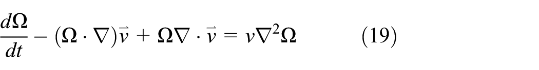
The vortex phenomenon actually is the progress of vortex generation, growth, and spreading with the energy dissipation, attenuation, and collapse. In terms of the barotropic fluid, with the potential forces acted, the Friedmann equations can be simplified, as shown in equation (19)
For the incompressible fluid, the distribution of vortex obeys the vorticity transport equation

Assuming

Thus, equation (19) can be simplified as

In polar coordinates, equation (22) can be expressed as

Equation (23) is the exponential function abided by the vortex attenuation

According to
Therefore, the mathematical models of the vortex generation, development, and collapse can be obtained from the above, and they are shown as equations (15), (18), and (23), respectively.
The modeling establishment and numerical methods
The parameters of model pump and meshing
To establish the calculation model, the type of 150 × 100LN-32 screw centrifugal pump is selected, and its performance parameters are as follows: volume flow qV = 165 m3/h, head H = 32 m, rotating speed n = 1480 r/min, and the shaft power P = 23.2 kW.
In the calculation domain, can be classified as non-structure tetrahedral mesh, where the total number of entire flow channel grid nodes is 89,403, the total number of units is 507,886, and the grid independency is checked. Then, given each segment model and meshes are shown in Figure 5.

The computation domain and grids of the screw centrifugal pump.
The numerical methods
The screw centrifugal pump runner is made up of the impeller and the volute; considering the rotating coordinate system on the surface of the impeller as the relative coordinate system, the flow in the impeller can be seen as steady flow, while the entire flow channel inside is a three-dimensional incompressible steady turbulence field. Apply the import and natural outflow speed boundary conditions, respectively, to the inlet and outlet of pump, apply the no-slip boundary conditions to the import segment, the impeller cone section, the volute wall, and other solid wall, as well as apply the standard wall function5,6 to the regions near the solid wall. By establishing continuous equations, N–S equations, and other control equations in the relative coordinate system, using the standard k − ε turbulence model can make these equations closure.7,8
According to the specific circumstances of water and sediment containing in the solid–liquid two-phase flow, the Mixture multiphase flow model is chosen. To ensure the premise of accuracy by saving the computing time as little as possible, the first-order upwind scheme is chosen on the discrete of the convective terms,9,10 the central difference scheme is used on the dissipative terms, the convergence precision is set to 10−5, and the SIMPLE algorithm is taken to solve the pressure–velocity equation with the iterative solutions.
The judgement of the vortex generation in the screw centrifugal pump
The sandy water is used to simulate the solid–liquid two-phase fluid transported by the screw centrifugal pump. The liquid water is the first phase, and the solid phase of sand is the second phase. Assume that the volume fraction obeys the uniform distribution during the import of the pump 11 and is equal to the solid delivery fraction in the numerical simulation calculation when the volume fraction of the solid particles vof is defined. 12
Figure 6 shows the distribution of the streamlines in the middle section in the axial direction in the type of 100LN-7 screw centrifugal pump within a unsteady flow cycle; thus, the distribution and evolution of the vortex can be seen clearly.
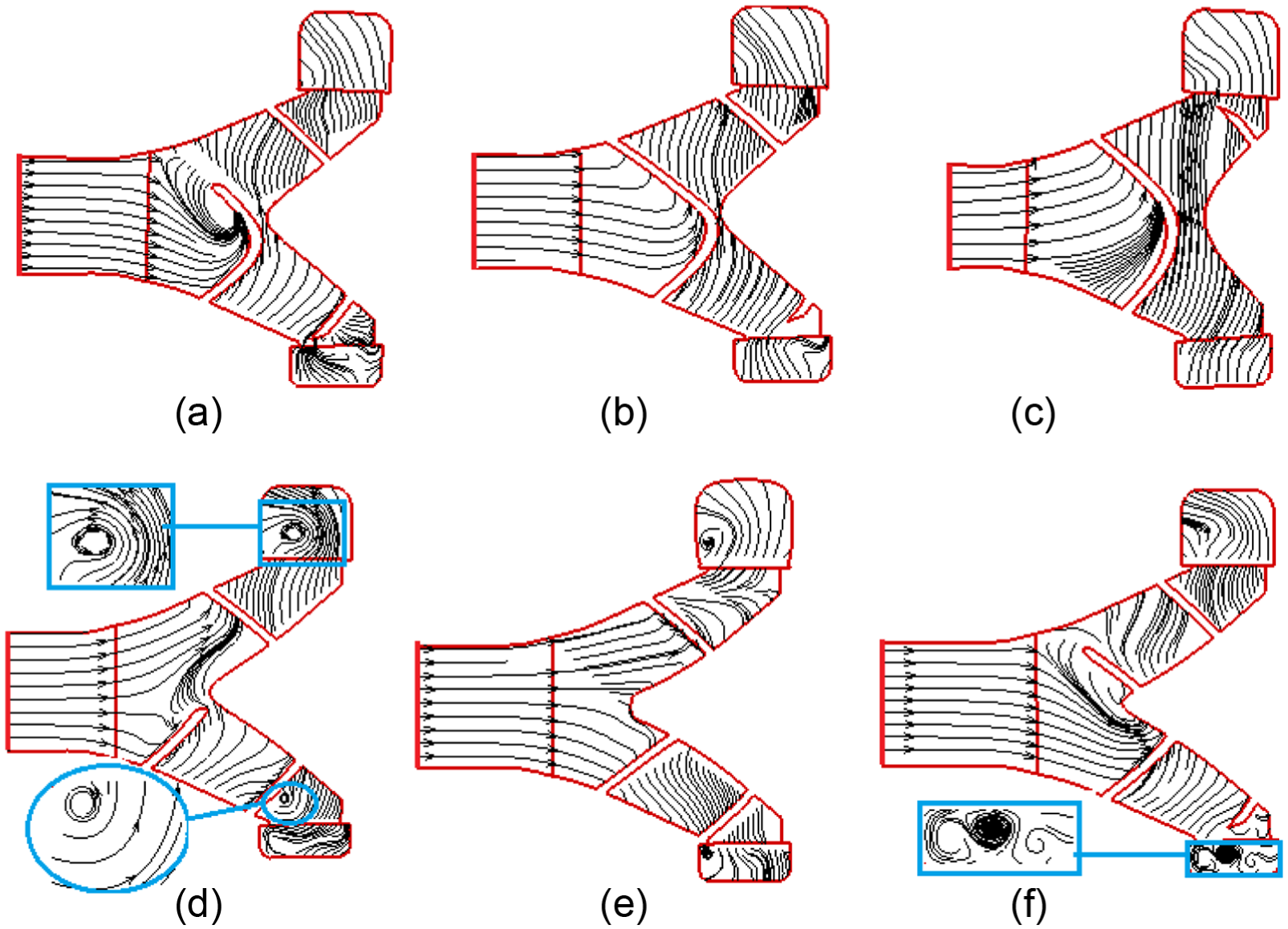
The axial flow lines and the progress of the vortex evolution: (a) t = T/6, (b) t = 2T/6, (c) t = 3T/6, (d) t = 4T/6, (e) t = 5T/6, and (f) t = T.
As shown in Figure 6, the fluid velocity distribution in space is continuous, while the flow lines locate at any one time, and the flow lines represent the instantaneous motion of fluid particles in the same flow line on the flow field. Therefore, the emergence of vortex can be intuitively judged by the flow lines.
From Figure 6, it can be seen that in the middle axis direction section of the screw centrifugal impeller, vortex appears on the head of the impeller and the runner of the impeller in the volute, and these can be observed in the amplified figure of Figure 6. These locations are the places where the pump flow runner changes the fluid velocity greater, especially the direction of the velocity; next, we will analyze the deeper reason of those combined with the change in pressure and vorticity.
From Figure 6(a)–(f), the evolution of vortex generation, proliferation, and collapse in the middle axis direction section of the screw centrifugal pump can be seen. In Figure 6(a), at the time of T/6, only the head of impeller has the trend to generate the vortex, which is due to that the fluid entering the pump chamber impacts the head of the impeller, induced by velocity change; in Figure 6(b) and (c), namely, from the time of T/3 to the time of T/2, flow lines distribution is more uniform; in Figure 6(d)–(f), namely, from the time of 2T/3 to the time of T, the vortex appears in the impeller channel of the centrifugal segment in the volute and turns on a trend to increasing and then will flow into the next cycle with the rotation of the impeller, and complete the next of process vortex evolution.
Figure 7 shows the flow lines distribution of the screw centrifugal impeller with the pressure within a rotating cycle, and Figure 8 shows the vortex distribution with the volume fraction of Cv = 10%, Cv = 20%, and Cv = 30%, respectively, and can analyze the effect of the volume proportion on the vortex distribution. From Figure 8, it can be seen that with an increase in the solid–liquid two-phase fluid volume concentration, the quantity of vortex increases and the scale of vortex becomes more obvious in the axis direction section, while the spiral segment of impeller flow line is relatively stable, and these vortices occurred mainly in centrifugal impeller segment. It also shows that with the full action of the impeller, the fluid, on the axis direction section, and the quantity of vortex are more and take up the larger areas than other locations. Combined with Figure 7 to analyze, in terms of the positioning the vortex generation, in the front screw section, the fluid flows smoothly into the pump chamber and the flow lines are relatively flat, while in the rear screw section, the pressure gradient changes significantly, which shows that the flowing media in the flow runner are not smooth and there are a wide range of impact flow and back-flow; however, the flow lines in the flow channel which contact with the second half segment and the centrifugal section exits the vortex obviously. And in the outlet segment of the volute, the flow lines are significantly distorted, and it is the reason why the hydrodynamic energy shifts to the potential head, making the velocity gradient change greatly. Especially in the rim section of the centrifugal impeller, the isodensity and the isobaric surface are oblique, and there exists vortex obviously. Therefore, it is the change in density that generates the buoyancy force, which leads to the fluid stratified further, as well as the isodensity lines and isobar lines intersect, and finally, form the vortex.
The distribution of flow lines with pressure: (a) t = T/4, (b) t = T/2, (c) t = 3T/4, and (d) t = T.

The effect of the volume proportion on the vortex distribution: (a) Cv = 10%, (b) Cv = 20%, and (c) Cv = 30%.
Comparative analysis of the experimental test and numerical simulation results
Performance test and particle image velocimetry measurement system
Whereas the open experiment platform has the advantages of simple structure, easy to operate and control, and better thermal conditions and stability to meet the test requirements, in consideration of the cost of the experiment platform, the open loop experiment platform is established, as shown in Figure 9.
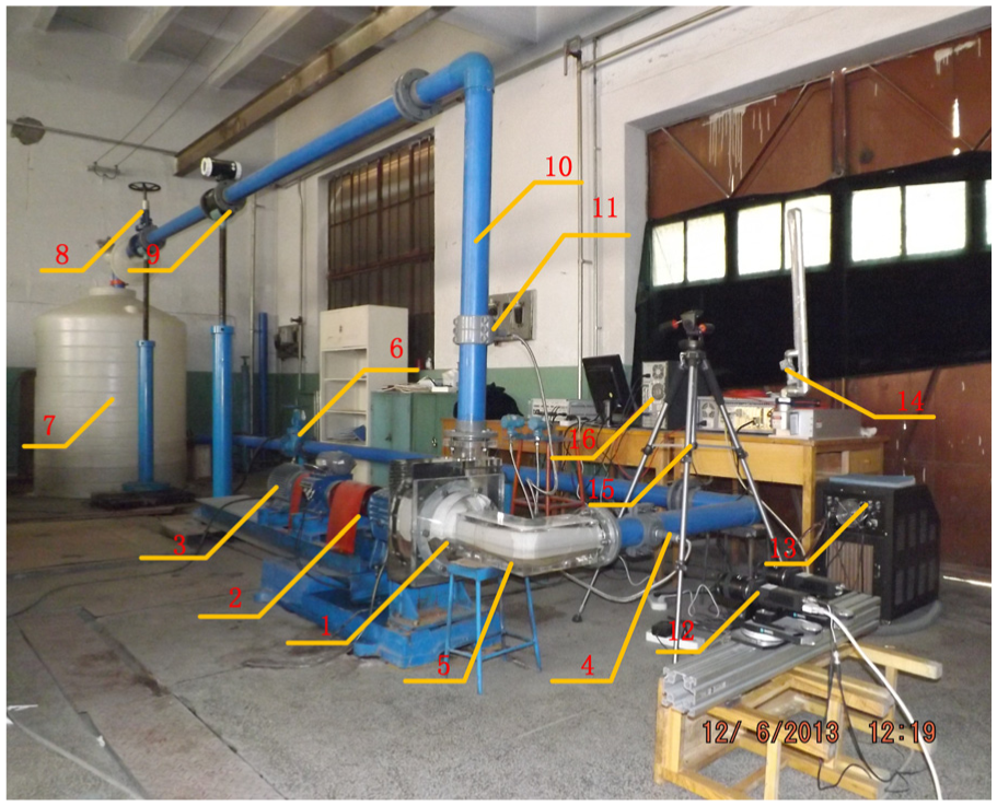
The open PIV test comprehensive experiment platform for the type of 100LN-32 screw centrifugal pump.
Comparative analysis of performance experiment results
The type of 100LN-7 screw centrifugal pump performance curves is shown in Figure 10, with the experimental test and numerical simulation results at steady flow state. From Figure 10, we can see that both the head-flow rates curve and power-flow rates curve of the experimental and numerical simulation are very approaching, and the differences between experimental and numerical simulation results are quite small. The differences between experimental and numerical simulation values are relatively unstable in the efficiency-flow rates curve. When the volume flow rates are in the range of 0–40 m3/s, the average error of experimental and numerical simulation is 6.9%; when the volume flow rates are in the range of 40–80 m3/s, the average error is 2.8%; when the volume flow rates are in the range of 80–110 m3/s, the average error is 3.2%, and the average error over the entire flow range is 4.3%. Thus, the numerical simulation method in this article is reasonable and reliable, which has been proved by the experiment, and the method can meet the demand of performance prediction in screw centrifugal pump.

The type of 100LN-7 screw centrifugal pump performance curve with steady flow state.
Flow field testing and vortex evolution analysis
In order to describe flow characteristics of the internal fluid in the type of 100LN-7 screw centrifugal pump better, a series of axial sections and radial sections which are perpendicular to the laser light sheet were selected. In this way, it is easy to access the physical quantities on those cross sections by the particle image velocimetry (PIV) testing technology. The sections being selected and their shape are shown in Figure 11.

Schematic diagram of the testing sections selection and their shape: (a) axial section and (b) radial section.
By the technique of shooting particles with charge-coupled device (CCD) camera based on PIV, the image of the flow field is acquired. Then, these images are calculated using the Microwave software and the data are processed by the Tecplot software. Finally, both the instantaneous flow field and the flow information of each section in the type of 100LN-7 screw centrifugal pump are obtained.
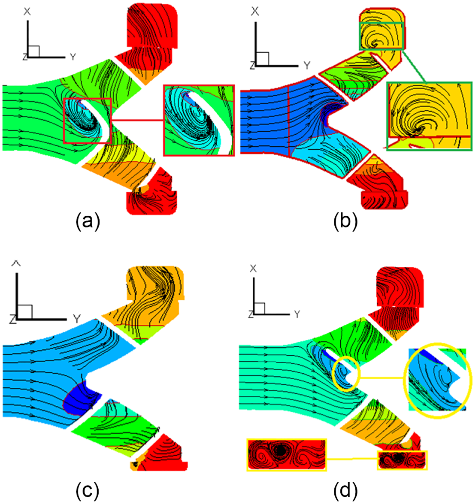
Figure 12 shows vortex streamline identification and vortex evolution process. As Figure 12 shown, on the streamline disordered regions the vorticity changed greater and more obviously, which have proved by the results of PIV testing. The vortex is appeared in the impeller axial section, while the remaining sections streamline perturbations are quite small. This situation quite differs from the PIV testing results. Those phenomena can be explained as follows. There are many unpredictability and measure factors during the PIV testing, such as the vibration of the pump, the random and systematic errors of the test system, especially for the reason of some testing blind regions existing. Thus it is difficult to characterize the fluid flow process completely.

Vortex streamline identification and vortex evolution process.
Conclusion
In the solid–liquid two-phase flow pump, the forces of the stratified fluid acted are different, the change in density in the pump generates the buoyancy force and leads to the oblique of isodensity lines and isobars and finally formed vortex.
With the viscous of the fluid acting, the vorticity diffused into the flow. As well as with the flowing section area changing, some of the flow velocity is acceleration, while another is deceleration, and both situations motivated the vortex generation, those progresses are the root cause of the vortex generated. At the same time, the work provided by the rotating machinery components leads to the reconstruction of the fluid spatial distribution. In this way, the pressure gradient and concentration gradient are non-orthogonal in space, and the shear force appears between the flow layers. While the shear force direction and the velocity direction forms a certain angle. This angle is the direct reason of the vortex generation. However, when the medium is the solid–liquid two-phase fluid, it has the force field and the flow field both changed greater. Thus, the solid–liquid two-phase fluid can play the promotion or inhibition role of the vortex generation.
An important feature of the solid–liquid two-phase flow is imbalance, and this imbalance of the turbulent flow in the screw centrifugal pump has the two most important manifestations of the vortex and stratification, which reflect the irregular function relationship in time and space among the physical field quantities of the turbulent motion, for example, the velocity and the pressure, and its essence is the diffusion of the fluid mass and energy in time and space with the impeller machinery action.
Footnotes
Academic Editor: Hongwei Wu
Declaration of conflicting interests
The author(s) declared no potential conflicts of interest with respect to the research, authorship, and/or publication of this article.
Funding
The author(s) disclosed receipt of the following financial support for the research, authorship, and/or publication of this article: This work was supported by the National Natural Science Foundation of China (NSFC) (Nos 51609113 and 51579125). And also supported by Provincial and ministerial discipline platform open subject of Xihua University (No. szjj2016-075).