
Abstract
Failure of aircraft tires is a common cause for aviation accidents, whose results range from abnormal taking-off and landing process to fatal air crashes. Those consequences should not be neglected; hence, an authentication of airworthiness is necessary for the development of new aircrafts. Failure of aircraft tires can be caused by numerous factors and can be categorized into various modes. The related tests are of great significance for newly developed aircrafts to pass the authentication system. However, failures of aircraft tires can be unexpected, drastic, and extremely dangerous, which adds to the difficulties in tests. Besides, the test methods used currently contain insurmountable defects. In this article, a new test apparatus is developed to research the blowout of bias aircraft tires, which is in accordance with the Joint Aviation Authorities standard, and a test scheme is designed. With the jet flow field formed by the test apparatus and the comparison between simulation results and test data, the reliability of the test apparatus is proved. Ergo, a new test method for the airworthiness authentication of tire failures has been developed.
Keywords
Introduction
Aircraft tires are important devices which complete the take-off and landing process of planes. Meanwhile, the tires work under heavy loads, harsh functioning environments, and great variations of tire pressure, which subject them to blowouts. There are complex factors that could result in aircraft tire blowouts, among which manufacturing defects and misuse are the main causes.1,2 A majority of aviation accidents are caused by failures of aircraft tires, and this has drawn the public’s attention. To make tires more secure and reliable, agencies like Joint Aviation Authorities (JAA) and European Aviation Safety Agency (EASA) request that blowout tests be run on the key parts in the main gear cabin, which aims to access the dynamic response characteristics of these parts. Till now, main relative standards are the JAA Temporary Guidance Material, TGM/25/8 (issue 2) Wheel and Tire Failure Model by JAA, 3 and the 2013-02 Notice of Proposed Amendment (NPA) by EASA, 4 both of which have elaborate rules on failure modes which occur in cruise or the take-off and landing process. Hence, blowout tests have to be carried out according to different failure modes.
Among the aircraft tire failure modes given by standards of JAA and NPA, special attention should be paid to the mode of tire burst pressure effect. This very mode happens after the plane takes off when the aircraft tires are back in the main gear cabin, and it is often caused by undiscovered damages in the tires. When the aircraft is cruising high in the sky, due to an increase in the pressure differential between the inside and outside, the aircraft tires are prone to blowout.
Today, aircraft tires mainly consist of bias tires and radial tires with different shapes of flow field nozzles and tire burst pressure effect mode irrespectively. 5 The tire burst pressure effect mode when a bias tire bursts is shown as Figure 1. These two criteria stipulate that this model merely concentrates on air-jet pressure effect while ignoring forced outward fragments when a tire blows out.3,4

A recommended model for tire burst pressure effect mode of bias tires blowout: (a) JAA TGM/25/8 and (b) EASA NPA 2013-02.
Test studies of tire blowouts are of great significance to not only airworthiness authentication and security in flying but also the tire industry. 6 Correlational studies have already been conducted by all the major tire manufacturers worldwide; however, it is, to a certain degree, especially professional, technically difficult, expensive, risky, and hard to get into. In the test by Megan, polished B-52 and F-16 were first fixed and tire burst tests were carried out. The pressure data were obtained via sensors placed around tires 900 mm away. 7
A regional jet is utilized in the tests, which is independently designed and manufactured by China according to the international standards of airworthiness. The security test of the key parts in the main gear cabin was carried out by Michelin and Cie and the process is shown in Figure 2. In the test, Michelin and Cie, first, determined grinding areas and depth by experience; second, fixed the polished tire on the test table; third, inflated the tire to 1.825 MPa, then fixed a resistance wire on the central part of grinding surface, and finally, the ohmic heating resistance wire burned out ungrinding cord threads to simulate tire blowout. Meanwhile, the collection of pressure signals would be done by the sensors as shown in Figure 2. 8
A test diagram of tire blowout of Michelin and Cie: (a) photos of blowout spot and jet blast field and (b) layout of sensors.
As seen in Figure 2, only dynamic pressure data more than 500 mm (20 inches) away from the flow field nozzle were collected in the test. However, key parts in the main gear cabin of this plane were all within 500 mm from the nozzle, and therefore, dynamic response of the plane cannot be analyzed directly with the pressure data obtained during this test. Meanwhile, the blowout jet field produced in this test varies greatly from the model depicted in Figure 1 in terms of nozzle shape, size, and the shape of jet flow.
In conclusion, there is no method to accurately measure the jet blast field produced when an aircraft tire blows out, and its main reasons are listed as follows:
The blowout of tire is intense. The reproducibility of the test data is low as a consequence of uncertain size and position of flow field nozzle and yet a relatively fixed layout of sensors.
Fragments of different shapes flying at a different speed are inevitably forced out in the process of aircraft tire blowout, directly impacting and damaging proximal sensors, and therefore, pressure data within 500 mm cannot be collected.
To solve the above problems, in this article, a set of test apparatus combing deflagration system with plate values is designed according to the standards of JAA and NPA, and jet field close to the nozzle is measured.
Test study
Test apparatus
The designing idea is to create a round hole on the surface of aircraft tire to simulate the blowout nozzle according to the size shown in Figure 1. First, the tire body is fixed to the apparatus tightly and the blowout nozzle is sealed with a pair of plate valves. When the tire is charged to working pressure, deflagration power system is connected to plate valves to turn on the plate valves synchronously to simulate the jet field from the blowout of bias tires realistically. Its physical maps and three-dimensional (3D) diagrams are shown in Figure 3. This set can efficiently avoid the shortcomings of previous tests:
The jet flow field model prescribed in JAA and EASA standards is realized with the proposed apparatus, which increases the reliability of the dynamic analysis of the main gear cabin accessories.
No tire fragments are produced in the tests, which enables the closer locations of sensors so that dynamic pressure data within 500 mm could be obtained. This is of great significance to exploring the pressure distribution rules of the jet field and further studies.
The flow field nozzle produced with this set of equipment is fixed, which facilitates the test and allows a stable flow field, making it convenient to repeat the experiment.

Diagrams of test apparatus: (a) physical map of test apparatus and (b) 3D map of test apparatus.
Structure and working principles
Deflagration dynamical system
The deflagration dynamical system is mainly comprised of a piston cylinder (No. 11 in Figure 4), a piston (No. 12 in Figure 4), gunpowder (No. 10 in Figure 4), and so on. Both the standards of JAA and NPA do not regulate the exact time when the blowout nozzle should be turned on. In order to stimulate the blowout process, the opening time of the plate valve (No. 7 in Figure 4) is supposed to resemble that of the real blowout. According to the blowout process recorded by a high-speed camera, the opening time of blowout nozzle is less than 5 ms under all circumstances. As shown in Figure 1(a), the diameter of the jet flow nozzle is 80 mm, and it takes about 100 ms for solenoid plate valves to be turned on whereas the time needed for pneumatic plate valves being longer, therefore, neither solenoid valves nor pneumatic valves can meet the time requirement. The turning-on of the nozzle in this apparatus is powered by high-pressure air let out in the process of high-performance gunpowder detonation. To overcome the reactive force of the explosion, a symmetrical plate valve structure is utilized. However, the synchronism problem has to be solved in the proposed design. For the purpose of satisfying both opening time and synchronism requirements, various gunpowders are tested, and an electric detonator is innovatively employed simultaneously, which makes two symmetrical plate valves opened at the same time. As the test results show, it only takes about 3.8 ms to turn on plate valves. And there is a time synchronization error for the operating the dynamical system of less than 0.3 ms for the whole process of turning-on.

An assembly diagram of test apparatus.
Sealing system
This type of aircraft tire has a tire pressure of 1.73 MPa, which requires an extremely high sealing standard to simulate the blowout process. The sealing system of this apparatus is comprised of the seal between the apparatus and the tire body as well as the seal of plate valve’s structure. The seal between the elastomer and the rigid body is a worldwide problem. In order to reach a reliable seal between the apparatus and the round hole on the surface of tire (No. 2 in Figure 4), a bowl-shaped clamping ring (No. 5 in Figure 4) is designed in this article, the structure of which is shown in Figure 5. To seal the apparatus and tire effectively, the bolt and tire body are sticked together with AB glue for aviation and then bowl-shaped clamping ring is employed to compress them. The seal of plate valve’s structure is completed by compressing the seal ring (shown in Figure 6) at the joint and lower parts of the plate valves (No. 6 and No. 8 in Figure 4). The results show that this hermetic method satisfies the design needs which require at least five times of repeated tests.

Bowl-shaped clamping ring.

The seal ring for plate valves.
Test system
The test apparatus consists mainly of pressure sensors, a DH5927 dynamic high-speed data collecting instrument, a bearing and a bracket (as shown in Figure 7), and so on. To ensure the measurement of the jet field is accurate enough, a layout scheme of sensors is proposed in this article as follows:
Employ thin-polished sensor bearings so that the potential influences from the array of sensors to the jet field could be reduced.
Dispose all sensors in a 3D way so that the jet field test could be run in three dimensions.
Try to match the test spots with key parts in the main gearing cabin in the following tests.
Alternatively, test the spots multiple times where they could possibly interfere with each other.
Sensors near the boundaries are adjustable so that boundary values of the jet field could be exact.
The layout of sensors: (a) the sensor distribution in real application and (b) the schematic diagram of sensor distribution.
Test scheme
According to the requests for blowout spots from the aircraft tire blowout test, a round through-hole should be cut at a specified place on the tire surface. The size of the hole should follow the principles of fluid dynamics, the actual sizes of the tire, and the JAA standard. The water jet cutter is harnessed for processing the jet hole and the bolt hole, and the method of milling is employed for processing the counter-bores for the sealing rings and the bowl-shaped clamping rings. Both techniques are used for the sake of leakproofness and in order that walls of holes could be free from any damage possible.
Metal boards (No. 1 in Figure 4) should be closely connected to the body of the tire (No. 2 in Figure 4) with bolts. To ensure the airtightness, the bowl-shaped clamping rings mentioned above and the AB glue for aviation are utilized. The test apparatus is tightly attached to the metal board (No. 4 in Figure 4) via whorl threads.
As shown in Figure 8, the apparatus is fixed on the test bearing, and the array of sensors and the data collecting system are all laid out as planned.
Set the electric detonator and gunpowder in the piston body of No. 12 shown in Figure 4.
Use the adjusting board (No. 13 in Figure 4), which is fixed at the bottom of the piston cylinder (No. 11 in Figure 4), and rotate simultaneously the two adjusting bolts (No. 14 in Figure 4) so that the two plate valves (No. 7 in Figure 4) can connect and seal with each other. This sealing hereby could withstand a pressure of no less than 4 MPa. The airtightness of the flow field nozzle during the tire pressurizing process is realized via the sealing system.
Pressurize the aircraft tire till 0.5 MPa, and remove No.13 and No.14 shown in Figure 4, then, continue to pressurize till the pressure reaches 1.75–1.76 MPa.
Ignite the gunpowder block with the electric detonator (No. 10 in Figure 4). With the push from the gunpowder, the piston (No. 12 in Figure 12), together with the plate valves, moves to the opposite direction in the slideway, thus turning-on the jet filed nozzle to simulate tire burst. Meanwhile, data could be collected via the test systems for further references.

Apparatus of the jet blast field test system.
Test results and analysis
Figure 9 shows the time–overpressure relation at different position. All the pressure values given below are the difference between real pressure and standard atmospheric pressure. The data obtained at S2, S3, S4, S5, S6, and S7 are depicted in Figure 7, which represent the relation between time and overpressure.
Six time–overpressure relation diagram.
It can be concluded from Figure 7 that, despite the fact that S2, S3, and S4 share a same distance to the center axis of the detonation, the maximum overpressure value is reached at S2. S3 and S4 are symmetric from the center axis, and ergo has a similar overpressure maximum value as well as a time–overpressure relation diagram. Same theory is also applied to S5, S6, and S7.
Since the ultimate goal of the research is to find out the influence of jet flow upon the security of key parts in the cabin, the focus of the research should be drawn to the maximum overpressure at the axis. The analysis of the changes of overpressure condition and time can be used as reference for following tests. The tested values at different spots along the axis are listed in Table 1.
Overpressure peak value at the axis.

According to the statistics from the selected test points, the overpressure peak value decreases apparently as distance increases. S23 is 537 mm from the detonation axis and has a similar peak value with the tested value at a distance of 20 inches (508 mm) by Michelin and Cie, which indicates that the apparatus in this article can satisfy the design needs well.
From Figure 9 and Table 1, it can be concluded that the jet flow field created by this apparatus attenuates as the distance from axis increases. And at the same distance, the value at inner side is larger than that at outer side. The above conclusions are in accordance with the classic theories of jet flow field of tire blowout. It is also proved that this apparatus can develop a cone jet flow field stipulated by standards of JAA and NPA. In addition, results from multiple tests show that overpressure at all spots is less than the maximum allowable value, while overpressure in previous tests varies drastically. Therefore, it is proven that the proposed apparatus can be used to create stable jet flow field.
The standard by NPA is based on the foundations of that by JAA. In comparison to the latter, the former has more conservative standards on fragment sizes, velocity, and so on, yet the two standards specified different cone angles under the tire burst pressure effect mode. According to the standard by JAA, the cone angle 2α equals 36°, whereas in terms of the NPA standard, that is 18°. Time–overpressure relation diagram is plotted in Figure 10 as J2. The included angle between J2 and the vertex of the cone angle is 18.7°. It has been confirmed through tests that the vertex angle is 36°–38° approximately, which shows, by contrast, the standard of JAA corresponds more to reality than that of NPA does.
J2 time–overpressure relation diagram.
In this article, the commercial software FLUENT is used to stimulate the blowout process. The blowout simulation is shown in Figure 11.

Sketch map of the transverse section of the simulation.
Figure 12 depicts the relation between distance in axial direction and overpressure when the nozzle becomes the biggest. It is obvious from the figure that the pressure at the axis matches those peak values back in Table 1. For further research, S5, which is 142 mm from the nozzle, is selected in our research. Figure 13 gives the overpressure diagram at the distance of 142 mm in the radial direction.

The distribution of the overpressure in the axial direction.
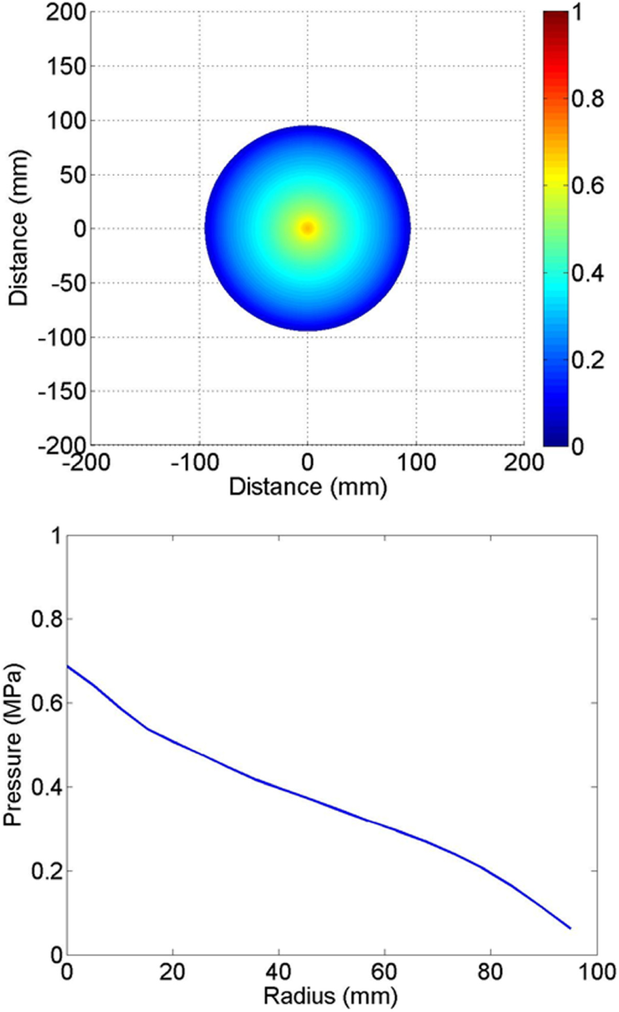
The distribution of the overpressure at 142 mm in the radial direction.
The time–overpressure relation diagram which is 144 mm from the detonation axis by FLUENT is shown in Figure 14. For comparison, Figures 14 and 9 are redrawn as Figure 15. As is observed from Figure 15, the simulation result agrees well with tested result, which proves the reliability of the proposed apparatus.
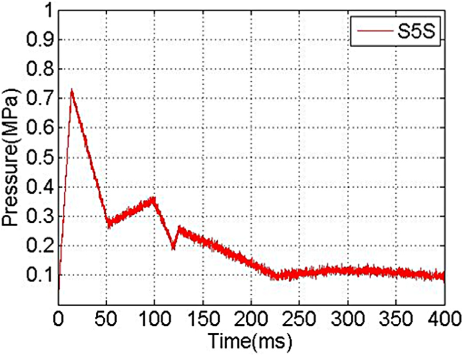
S5 time–overpressure relation diagram (simulation).

S5 contrasts between simulation and test.
Conclusion
Failure of aircraft tires is a common cause for aviation accidents. Therefore, it is of vital significance to conduct an authentication of dynamic responses of key parts in the main gear cabin. A new set of test apparatus has been established for stimulating the blowout of aircraft bias tires, and the test process has accordingly been designed. After comparing the experiment data of Michelin and Cie and the simulation data, it is proved that bias aircraft tire blowouts can be simulated. The statistics within 500 mm from the jet flow nozzle have been collected for further research. In designing the apparatus, the following three aspects are researched:
To simulate the real aircraft tire blowout process, a new detonation-powered device has been established. An electric detonator lighting method has been put forward so that the plate valve opening time could resemble that of the tire blowout, which makes opening time and synchronism time less than 5 and 0.3 ms, respectively.
To satisfy the leakproofness needs of the device, explorations into the airtightness of elastomer and stiffener have been made, and several test methods are designed. Eventually, the bowl-shaped clamping ring with aviation AB glue way is adopted, which is in line with the standards.
To overcome the drawbacks of previous test methods, sensors in the proposed method are located at different places in 3D space. The pressure distribution within 500 mm of the tire leakage is obtained, which is important for the analysis of dynamic response of the key parts in the main gear cabin. In addition, the shape of jet field is investigated.
Footnotes
Academic Editor: David R Salgado
Declaration of conflicting interests
The author(s) declared no potential conflicts of interest with respect to the research, authorship, and/or publication of this article.
Funding
The author(s) received no financial support for the research, authorship, and/or publication of this article.