
Abstract
Spring-supported fine particle impact damper which integrates the effects of elastic deformation and the plastic deformation performs excellently on the attenuation of vibration in cantilever beam. This article studies the damping performance of spring-supported fine particle impact damper experimentally and establishes a dynamic model for understanding its mechanism. Results of the modeling are compared with conducted experiments based on the defined dimensionless structure parameters. The effects of chamber clearance ratio, stiffness ratio, and power ratio are analyzed with the model. As a result, it is shown that the spring-supported fine particle impact damper reduces 80% of the maximum amplitude of cantilever beam at the resonance point which is better compared with the 40% reduction of single impact damper; the dynamic model of the spring-supported fine particle impact damper is reliable, and there exists optimal structure parameters which are 0.15 of clearance ratio and 0.007 of stiffness ratio for achieving the best damping performance.
Introduction
As one of the passive damping techniques, impact damper controls the response of the primary system by utilizing the impact between the free mass (the impactor) and the primary system during a vibration process. Due to its simple structure, low cost, easy implement without external power supply, adaptation to harsh environment, and good damping effects, studies on impact damper have been rapidly developed.
The early impact damper is the single-mass impact damper (SMID), which controls the vibration by the impact between the single impactor and the primary system. 1 It is demonstrated that a properly designed SMID is effective in reducing the response of the primary system. However, the high level of noise and strong contact force which may cause local damage to the structures has limited the application of SMID. Many efforts have been made to overcome these shortcomings and improve the performance of impact dampers. Popplewell and Semercigil 2 found that the bean bag impact dampers were more effective to reduce the acceleration, contact force, and peak response. Masri, 3 Bapat and Sankar, 4 and Saeki 5 proposed a concept of multiunit impact damper to decrease the velocity discontinuity of the primary system in impact. Particle impact damping (PID), which substitutes single impactor with filled particles, is a derivative of SMID.6–9 Nonobstructive particle damping (NOPD) 10 is a special form of PID which introduces damping to a structure by filling particles into cavity created within the structure. Li and Darby 11 introduced a buffer region between the mass and the stops to reduce both acceleration and contact force in collisions. Du and colleagues12–14 proposed a new fine particle impact damper which introduces plastic deformation of fine particles to vibration system as perpetual energy dissipation. More and more attentions of researchers have been attracted to investigate the performance of PID.15–20
It is widely reported that during the energy-consuming process coefficient of restitution is a key parameter, the variation of which directly influences the damping effect. However, different viewpoints on whether the relation between them is positive or negative have brought about two different directions of research: (1) to maximize the coefficient of restitution based on nearly elastic collision for achieving better damping effects via effectively reducing the acceleration during impact process; one classic example is Li and Darby’s 11 buffered impact damper, and (2) to minimize the coefficient of restitution based on nearly plastic collision, such as using fine particle impact damper, 13 to perform more excellent damping effects under low-frequency vibration (below 50 Hz) than SMID and PID.
This article proposes a new spring-supported fine particle impact damper (SSFPID) as shown in Figure 1. The damper employs a double damping structure: the external is a spring damper with higher coefficient of restitution, while the internal is a fine particle impact damper with a lower coefficient of restitution. The fine particle impact damper, 13 consisted of a sphere impactor and a certain quantity of fine particles, is supported by springs at its two ends. The new damper is an integration of elastic deformation damper and plastic impact damper. The damping effect is maximized as the amplification effect of springs not only enables more momentum exchange but also does more strong impacts in inner fine particle impact damper. This article carries out the experimental study on the damping performance of SSFPID in a cantilever beam. A dynamic model of SSFPID is established and verified by the experiment data. In this article, the model is also used to analyze the effect of stiffness ratio, chamber clearance ratio, and power ratio for understanding the basic principles of the new damper.

Structure diagram of spring-supported fine particle impact damper.
Experiment of damping performance
Experimental device
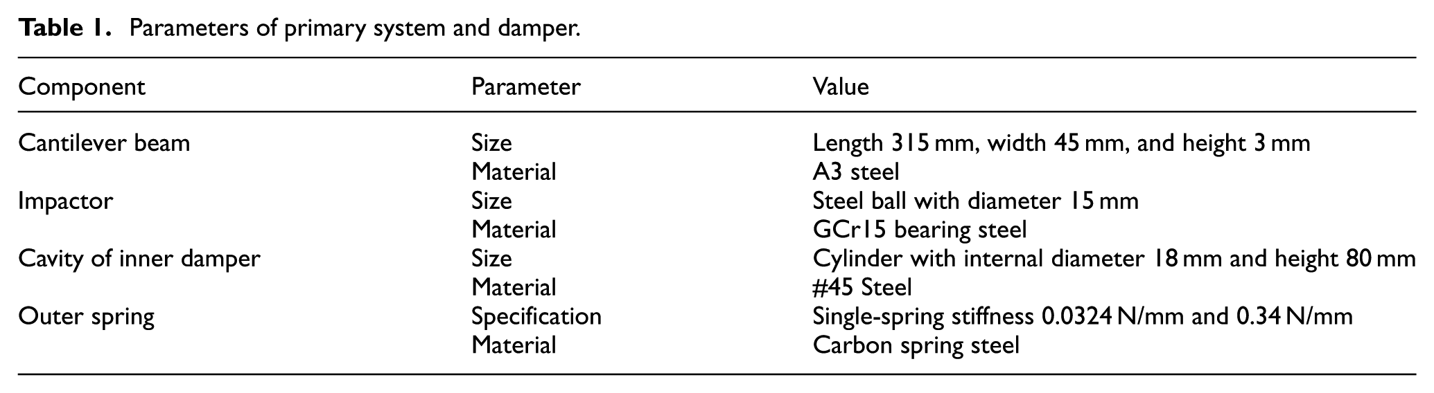
The purpose of the experiment is to investigate the damping effects of the SSFPID proposed by this article. Figure 2 illustrates the schematic diagram of experimental device, and the experimental device is shown in Figure 3. An electromagnetic vibration exciter is used to excite the root of a cantilever beam with sinusoidal signal. The damper is placed at the end of the cantilever beam, and an accelerometer is equipped to measure the amplitude of the end of cantilever beam. The damper is consisted of inner cylindrical cavity and outer spring. An impactor and a certain amount of fine particles are placed in the cavity. Up to eight groups of spring are connected to both ends of the cavity, as shown in Figure 3. The parameters of the primary system and the damper are shown in Table 1.

Schematic diagram of experimental device.

Picture of experimental device.
Parameters of primary system and damper.
Experimental scheme
Experimental studies are performed on the cantilever beams with different types of impact dampers. Based on different components in damper cavities (shown Figure 1) in Table 2, the experiment is grouped into four cases to test the vibration attenuation effects on cantilever beam. In these four different cases, the vibration damping effects of dampers are investigated via the vibration status of cantilever beam within the scope of the first flexural mode.
Components in damper cavities under different cases.

Experimental results and discussion
Figure 4 exhibits the experimental results of all four cases with dampers in Table 2 under harmonic excitation. Due to the effect of momentum exchange, the maximum amplitude of the single impact damper at the free end of cantilever beam decreases to 60% of the maximum amplitude with no damper applied; the maximum amplitude of the impact damper with fine particles is reduced by nearly 60% compared with no damper because of the plastic deformation of fine particles caused by the collision between impactor and damper cavity; the maximum amplitude of the SSFPID is reduced by 80% accordingly attributed to the double damping effect of the elastic deformation of outer spring and the plastic deformation of fine particles in inner fine particle impact damper. It can be concluded that the SSFPID brings a highest amplitude attenuation ratio and shows the most flat curve in Figure 4, which indicates the stability and adaptability of maximum amplitude to different frequencies.

Maximum amplitude of free end of cantilever beam in resonance point region.
Figure 5 shows the damping ratio of the damped cantilever beam under free decay vibration. In the experiment of free decay vibration, the free end of cantilever beam is given an initial displacement of 20 mm and then the displacement time history is measured under the condition of free vibration. The damping ratio of the cantilever beam with different dampers in Table 2 is calculated by the testing result of free decay vibration. As shown in Figure 5, the SSFPID has the highest damping ratio, which further indicates the good performance of the damper.
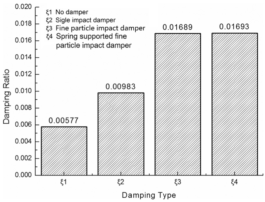
Damping ratio of different dampers under free decay vibration.
The SSFPID performs two damping mechanisms: the external spring support has a higher coefficient of restitution, which reduces the vibration by the elastic deformation of spring; the internal fine particle impact damper has a lower coefficient of restitution, which can completely consume the kinetic energy by the plastic deformation of fine particles. 13 The double structure makes full use of the characteristics of both damping mechanisms, maximizing the damping performance to a level that could be hardly achieved by traditional impact damper.
A dynamic model of SSFPID
Establishment of systematic differential equation
A 2-degree-of-freedom model is developed to represent the vibration model of a cantilever beam damped by the SSFPID in Figure 6. This system consists of three mass bodies,

Dynamic model of spring-supported fine particle impact damper.
For the convenience of calculation, assumptions are as follows:
The friction force among
This impact is inelastic, and the relation of the before and after impact is simulated by coefficient of restitution e;
Only vibration in the horizontal direction is considered.
The motion differential equation is

Provided that

is the mass matrix
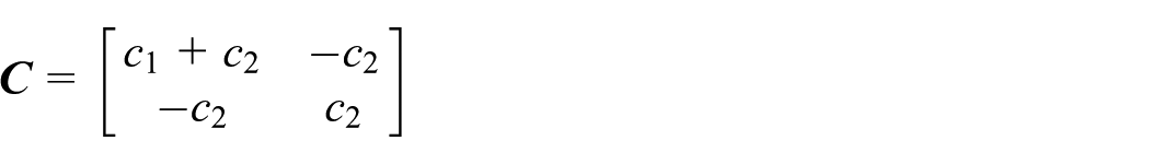
is the damping matrix
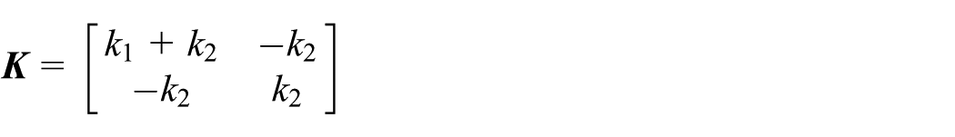
is the stiffness matrix

is the displacement vector
is the velocity vector

is the acceleration vector and

is the vector of exciting force.
So, the motion differential equation of the system can be represented as

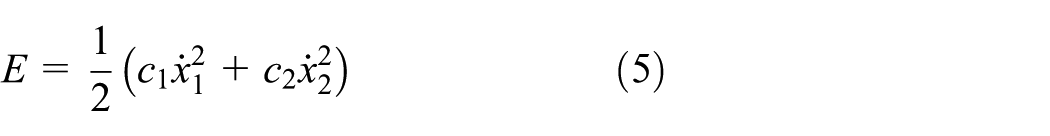
The system kinetic energy is

The system potential energy is

The system energy consumption function is
Modal analysis
Suppose the main vibration is

where
The system eigenequation is

By this equation, two eigenvalues
Modal matrix of this 2-degree-of-freedom system
Among the main vibration modes with the same inherent frequency, there is


where
Calculate the system dynamical matrix

Substitute formula (10) into the following one

Obtain eigenvalue
Coordinate exchange
The vibration mode matrix or the modal matrix could be illustrated as

To change the system coordinates as follows

Thus, the original vibration equation becomes

That is

where
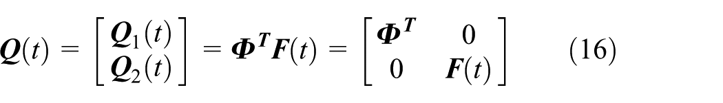
Also


So, the matrix after coordinate exchange is expressed as follows
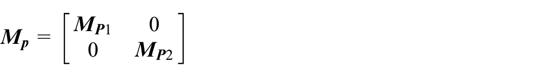
is the main mass matrix
is the main stiffness matrix and

is the damping matrix.
Steady-state response
In this way, there is a decoupling of formula (15), for the ith equation is

or

where

For

where

The system equation is

By Laplace transformation, the above equation is considered with a starting condition as 0

where
Given that

Say it as the transfer function matrix and then

To transform

In this formula, to make


Substituting formulae (23) and (24), the result is

To express the steady-state response of this vibration system as the following complex number form

To change the

Based on the above formula and formula (33), the result is as follows

This system is of 2 degrees of freedom, and therefore, n = 2, and the steady-state response of the system is illustrated as

Parameter calculation
The mass of the cantilever beam system,
The damping specific volume created by the damper is

where

Since the mass of

The impact acting on

Calculation procedures
This article uses MATLAB to program the mentioned calculation procedures. The flowchart of MATLAB simulation procedure is shown in Figure 7.

Flowchart of MATLAB simulation procedure.
Comparison between simulation results and experimental data
Several dimensionless parameters are defined below for better analyses:
Amplitude ratio: the ratio of system stable amplitude to amplitude without damper;
Frequency ratio: the ratio of excitation frequency to natural frequency without damper;
Clearance ratio: the ratio of clearance to amplitude without damper;
Stiffness ratio: the ratio of stiffness of additional springs to stiffness of the main system;
Power ratio: the ratio of input power to system rated power;
Amplitude decay rate

In this formula, AR represents the amplitude without damper and XR is the amplitude with damper.
Experiments take the clearance 36 mm; the copper powder as filled particles; the filling rate 20%; the mass of the impactor steel ball 0.024 kg; and the spring stiffness 0.34, 0.68, 1.02, and 1.36 N/mm, respectively. The comparison between modeling results and experimental results is shown in Figure 8. Figure 8 shows a favorable consistency between MATLAB simulation results and experiment results, which verifies the validity of the established dynamic model. The discrepancy between simulation and experiment results might be caused by the simplification of the model in which the plastic deformation of fine particles is simplified into the equivalent damping

Comparison between simulation results and experiment results under spring stiffness: (a) 0.34 N/mm, (b) 0.68 N/mm, (c) 1.02 N/mm, and (d) 1.36 N/mm.
Model calculation results and analyses
On the basis of established dynamic model, a numerical simulation is employed on the new damper to explore the basic principle and effect of structure parameters and find out the optimal parameters for achieving best damping performance.
Effect of clearance ratio
In order to determine the optimal chamber clearance value, the influence of clearance ratio on amplitude ratio is measured under the conditions of different stiffness values. It can be observed from Figure 9 that there is an optimal clearance ratio of 1.5. As the clearance ratio increases, the amplitude ratio first decreases and then increases.

Influence of clearance ratio on amplitude ratio.
Effect of stiffness ratio
The correlation between amplitude ratio and stiffness ratio is shown in Figure 10. There is an optimal stiffness ratio of 0.007 where the minimum of amplitude ratio is obtained. When the stiffness ratio is below 0.044, the amplitude ratio initially drops and then slowly increases. As the stiffness ratio is above 0.044, the amplitude ratio rapidly increases. The damper shows favorable performance below stiffness ratio of 0.044.

Relationship between amplitude ratio and stiffness ratio at resonance point.
Effect of power ratio
The influence of power ratio on amplitude decay rate is illustrated in Figure 11. From Figure 11, the system amplitude decay rate is approximately proportional to the power ratio. In other words, the higher the input energy, the better the damper’s damping performance turns out to be.

Influence of power ratio on amplitude decay rate.
Conclusion
This article carries out the experimental study and theoretical modeling for a new SSFPID. The integration of the elastic deformation of outer spring and the plastic deformation of inner particles makes the SSFPID exhibiting better damping performance than traditional impact dampers. The established dynamic model of the SSFPID is verified reliable to simulate the damping performance by the experiment. As known from the dynamic model analysis, to achieve the best damping performance, there is an optimal parameter combination for the new damper, which is clearance ratio of 0.15 and stiffness ratio of 0.007.
Footnotes
Academic Editor: Rahmi Guclu
Declaration of conflicting interests
The author(s) declared no potential conflicts of interest with respect to the research, authorship, and/or publication of this article.
Funding
The author(s) disclosed receipt of the following financial support for the research, authorship, and/or publication of this article: This work was supported by the National Natural Science Foundation of China (grant no. 51475308).