
Abstract
The vibration transmission paths between the fixed-mounted accelerometer and the meshing points of the sun gear’s local fault gear tooth is time varying in a planetary gearbox. Consequently, the conventional time synchronous averaging used in vibration-based fault detection of fixed-axis gearboxes is invalid for the localized fault detection of sun gears. To address the noise reduction, the windowed synchronous averaging originally introduced by McFadden can be employed to extract the useful components and reduce the effect of transmission paths. However, the speed fluctuation makes the above method inapplicable in real-world applications. In order to improve the robustness of windowed synchronous averaging under the speed fluctuation condition, a non-separation version of the windowed synchronous averaging in the angular domain is proposed in this article to address the speed fluctuation. In this scheme, the windowed time-domain signal is resampled at constant angular increments by the computed order tracking, which converts the non-stationary signal in the time domain into the stationary one in the angular domain. Then, the windowed angular-domain signal is processed by the synchronous averaging. In this way, the frequency blur and waveform distortion caused by rotating speed fluctuations can be eliminated. Experiments are conducted to verify the validity of the proposed method.
Keywords
Introduction
Planetary gear transmission is widely used in the rotating machinery, such as wind turbine and helicopter. However, due to the influences of operating conditions, manufacturing errors, assembly errors, multi-tooth meshing, and heavy loads, the vibration picked up from planetary gearbox exhibits nonlinear and non-stationary characteristics. 1 Especially, when the sun gear has early localized fault, the weak fault feature information is often masked by strong interferences. A failure of the sun gear may cause shutdown of the entire powertrain and thus result in major economic losses. 2 Therefore, the extraction of faulty sun gear is an important research topic in planetary gearbox diagnosis community.
Some recent researches use the de-noising methods, such as higher density wavelets (framelets),
3
to improve the signal-to-noise ratio (SNR). However, time synchronous averaging (TSA) is a powerful signal processing technique for the extraction of a periodic waveform from data containing both random noise and other periodic (non-synchronous) components. These periods are not integer times of a specified period.
4
Then, it is particularly useful for analyzing the vibration of gearboxes, as it enables the interesting components related to a specified rotating shaft to be extracted from the observed whole gearbox vibration. This method has been widely used in vibration analysis of fixed-axis transmission gearboxes. However, it may be invalid for planetary gearboxes, whose vibration responses are more complex due to its structure and unique planetary rotation in the fixed-axis gearboxes. For example, even in a simple one-stage planetary gearbox, there are many working parts, such as a ring gear, a sun gear, and several planet gears. In many applications, the ring gear is stationary and the sun gear rotates around a fixed center. The planet gears not only spin around their own centers but also revolve around the center of the sun gear. The planet gears are meshed with both the sun gear and the ring gear simultaneously. Due to these complicated gear motions and multiple vibration sources, the observed vibrations from planetary gearboxes are more abundant in spectral lines than that of fixed-axis gear systems. Moreover, the time-varying vibration transmission paths from the gear mesh points to fixed-mounted vibration transducer make the observed vibration rich in the modulations. Then, the conventional synchronous averaging (SA) scheme for the vibration of fixed-shaft gearboxes is not directly applicable to that of planetary gearboxes. To address this issue, some studies have been carried out for more than 25 years. For example, McFadden5,6 proposed a vibration separation method of planet and sun gears by time-domain averaging. Samuel et al.
7
studied the separation of planet gears’ vibration using multiple transducers methodology. Ha et al.
8
developed an autocorrelation-based TSA for condition monitoring of planetary gearboxes in wind turbines. Lewicki et al.
9
introduced a planetary gearbox fault detection scheme using vibration separation techniques. Hood et al.
10
proposed a vibration-based sun gear damage detection approach, in which the sun gear damage was confirmed by the presence of sun mesh groups. Although these works contribute to extract the useful components and reduce the effect of transmission paths in vibration signals of planetary gearboxes, the load applied on the machinery may not be a constant in the running condition. Moreover, the fluctuations of rotating speed are also inevitable in rotating machinery, which can lead to waveform distortion and the frequency blur. Order tracking
11
has been widely used to address this problem. The well-known computed order tracking (COT) scheme can be employed to convert the non-stationary vibration in the time domain into the quasi-stationary one in the angular domain via the so-called equi-angular resampling. By this way, the frequency blur and waveform distortion caused by the rotating speed fluctuation can be eliminated. The windowed averaging was originally introduced by McFadden
5
in the late 1980s, which can be employed to extract the useful components and reduce the effect of transmission paths. And it is suited to the limited capacity of the computer data processing, where the observed vibration is intercepted by a short window, and only the windowed data are kept and stitched together to form the so-called vibration separation vector. See reference
5
for details. With a rapid development in the computer technology, the data processing capacity is improved greatly. Then, the windowed data and the zeros data are utilized for the averaging directly without the splicing. However, the fluctuations in the rotating speed are inevitable in rotating machinery. In order to solve the speed fluctuation, a non-separation version of the windowed SA in the angular domain is proposed in this article to address the speed fluctuation. And the windowed procedure is introduced in detail, which is triggered by the tacho pulses of the sun gear. Furthermore, the characteristic frequency of the sun gear with a damaged tooth meshing with
The main contributions of this article can be summarized as follows: (1) a non-separation version of the windowed SA in the angular domain is proposed in this article. (2) The windowed procedure is triggered by tacho pulses. (3) The characteristic frequencies of faulty sun gears are further discussed.
The article is arranged as follows. The transmission path analysis will be introduced in section “Transmission path analysis.” The windowed SA for localized fault detection of sun gears will be introduced in section “Windowed SA for sun gear faults detection.” The proposed approach will be presented in section “Angular domain windowed SA scheme.” Experiments will be shown in section “Test experiment,” and conclusions will be drawn in section “Conclusion.”
Transmission path analysis
To facilitate the study, we assume the ring gear of the planetary gearbox is stationary, and the transducers are mounted on the gearbox casing which is connected to the ring gear. The fault-induced vibration at the meshing point has these possible paths, 12 which transmit the vibration to the fixed-mounted transducer through solid mechanical components. The structure is shown in Figure 1. In path 1, the vibration propagates from the meshing point to the ring gear, then from the ring gear to the gearbox casing, and to the transducer. In path 2, the vibration transmits from the meshing point to the sun gear, then to the sun gear shaft, and consequently to the supporting bearing, the gearbox casing, and the transducer. In path 3, the vibration transfers from the meshing point to the planet gear carrier through the bearing and the planet gear shaft, then to the planet carrier shaft, the bearing supporting the planet carrier shaft, the gearbox casing, and finally to the transducer.
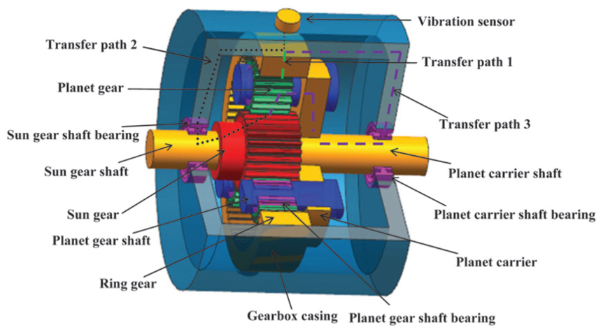
Transfer paths of the sun faults signal.
However, in the three paths, the localized fault-induced vibration transmitting through the path 2 or the path 3 will be attenuated significantly by their longer transfer paths, and especially by the damping of bearings. In this case, the observed vibration captured by the transducers will be negligible. Hence, the path 2 and the path 3 are not considered in the study.
However, the path 1 is the shortest, compared with the other two, and it does not involve bearings which cause complicated attenuation on the vibration. Then, most vibrations are observed by the transducer come from the path 1, and they contain much information of the faulty sun gear. However, this vibration transfer path is time varying due to the planetary motion of planet gears. In the planetary gear transmission theory,
7
the meshing frequency

where

And the frequency of a planet gear relative to the carrier

Based on equation (2), the transmission ratio of planet carrier and sun gear

Supposing

Vibration transfer path.
For one planet gear, in order to ensure that the number of rotation circles for both the sun gear and the carrier rotate is the smallest number of complete circles, the sun gear’s rotation circles need to be 99. Moreover, the carrier will rotate 28 circles, and the planet gear’s planetary motion will also be 28 circles. If the number of planet gears is
Windowed SA for sun gear faults detection
It is well known that the observed vibration for averaging is produced by the sun gear, and it is transmitted through the planet gears meshing with the sun gear. It is apparent that if the planet gear is getting far from the transducer mounted on the ring gear, the corresponding vibration to be observed is becoming small. Then, the dominant vibrations contribution will be the ones from the meshing teeth, which are relatively close to the transducer. As aforementioned, the vibration will be at its maximum level when the faulty tooth of the sun gear is just meshing at the nearest point (as shown in Figure 2) of the transducer. Then, the vibration transfer path between the point of fault gear mesh of the sun gear and the vibration sensor is changing from time to time (as shown in Figure 3(a)–(c)). This indicates that a higher SNR vibration can be achieved by only keeping the vibration when the planet gear is meshing with the sun gear and the ring gear just under the transducer location. To realize this idea to keep the vibration data series when one planet gear passes the transducer (e.g. accelerometer mounted on the ring gear), the output of the transducer is observed by a short window. This can be used to reduce the effect of time-varying transmission paths. Meanwhile, the parts that are in the originally observed vibration but not observed by the short window can be totally removed. Thus, this improves the SNR.

Vibration transfer path when the faulty tooth of the sun gear is meshing at: (a) position 1, (b) position 2, and (c) position 3.
Two important parameters are considered for the selection of a valid window: the window width and the window shape. 7 First, the window width is greater than one time of gear width. Because the observed vibration is not at the nearest position of the transducer, this can lead to slight waveform distortion. Second, the simplest window is a rectangular window. There are some small discontinuities at the position of the window overlap, which can attenuate the windowed vibration. This issue can be suppressed by the use of the window with smooth and symmetrical shoulders such as a triangular, Hanning, and Tukey windows. Lewicki et al. 7 indicate that the Tukey window is most appropriate; thus, it is chosen for this article.
The windowed SA originally proposed by McFadden
5
can be employed to obtain the higher SNR vibration and reduce the effect of transmission paths. The brief schematic is shown in Figure 4. The observed vibration is intercepted by a short window (Tukey window) once per circle of the planet carrier. It has several problems; first, only one window can pick up fault vibration of sun gear in vibration separation vector. The final analysis result can be a lack of robustness. Second, the windowed procedure is triggered by a period time of one carrier rotation,

Windowed synchronous averaging originally proposed by McFadden.

Isolation of sun gear vibration synchronous averaging procedure with the short window.
Angular domain windowed SA scheme
The COT and the windowed SA in the angular domain are two popular signal processing techniques for the feature extraction and fault identification. In this section, the COT and the windowed SA in the angular domain are briefly introduced, respectively.
Brief on COT
Since the loads applied on the machinery cannot be a constant in the running condition, the fluctuations in the rotating speed are inevitable in rotating machinery. However, in these varying-speed operation conditions, the vibrations generated by the machinery have time-varying frequency characteristics. To address this issue, the COT 13 scheme has been developed and widely used. However, the non-stationary signal with the time-varying frequency characteristics does not fit the Fourier transform strictly. It will lead to the frequency blur phenomenon in the spectral plots analysis. In the COT scheme, the picked non-stationary vibrations in the time domain are converted into the quasi-stationary ones in the angular domain by the equi-angular incremental sampling approach. Then, the frequency blur can be eliminated when one performs the fast Fourier transform (FFT)-based spectral analysis on the data series in the angular domain. The main steps of the COT are listed as follows: 11
The observed vibration and the tacho pulses of a selected reference shaft are multi-channels acquired simultaneously in the conventional way with constant time intervals.
The tacho pulses are utilized to calculate the speed profile by a quadratic or cubic fitting equation. 12 Then, the fitting equation is used to calculate the equi-angular incremental resampling time marks about the reference shaft.
The original picked vibration is resampled at the resampling time marks by a linear or spline interpolation algorithm. After the resampling, the corresponding quasi-stationary vibration in the angular domain is obtained.
The resampled data are calculated by the FFT-based spectral analysis methods. Then, the characteristic order lines corresponding to the faults can be exposed in the order spectral by the order analysis.
Angular domain windowed SA
To address the spectral analysis in the varying-speed conditions of planetary gearboxes, a combination of the COT and the windowed SA is introduced in this article. First, the original data series in the time domain are windowed once per circle of the sun gear. It is worth mentioning that the windowed procedure is triggered by the tacho pulses of the sun gear. Subsequently, the windowed time-domain signal is resampled at the constant angular increments. After that, the non-stationary vibration in the time domain is converted into the quasi-stationary one in the angular domain. Then, the windowed angular domain vibration is processed by the signal SA. The brief schematic of the windowed SA in the angular domain is shown in Figure 6.

Schematic of windowed synchronous averaging in the angular domain.
Test experiment
To verify the validity of the proposed method for real-world application, practical tests have been carried out on a planetary gearbox test rig (as shown in Figure 7). The sun gear has a faulty tooth, which is cut a crack at the root of the tooth by the electrical discharge machining (EDM) to simulate a real fatigue crack (as shown in Figure 8). The vibration is picked up by a DH112 accelerometer with a sensitivity 5.20 pC/g, and it is acquired by DH5923 (three-channel simultaneous sampling) data acquisition device. Meanwhile, the tacho pulse train generated by an eddy probe with a sensitivity 2.5 V/mm (as shown in Figure 7) is also acquired simultaneously to obtain the speed profile. The experimental parameters are listed as follows: the rotating speed of the sun gear is about ns = 1100 r/min and the setting sampling ratio is 50 kHz. The parameters of the planetary gearbox are listed in Table 1. The characteristic frequencies of each gear in the planetary gearbox are calculated according to the planetary gearbox configuration, its running speed, and the formula equations (2) and (3). They are listed in Table 2. The corresponding orders of planetary gearbox are calculated by

where

Experimental equipment of the planetary gearbox transmission.

Sun gear with tooth root crack.
Parameters of planetary gearbox.

Characteristic frequency of the planetary gearbox.

Order of the planetary gearbox.

A planetary gearbox includes a faulty sun gear with a damaged tooth and
Since the meshing points of the damaged tooth to planetary gears are not at the same position in a complete revolution of the sun gear to the planet carrier, the picked impulsive responses generated by the damaged tooth cannot be the same, whose phases are shifted at different meshing positions of the damaged tooth.
Due to inevitable errors from manufacturing and assembling of planetary gearbox, the damaged tooth is meshed with planet gears one by one. It cannot be identical in a complete revolution of the sun gear to the planet carrier.
In conclusion, the observed vibration generated by the faulty sun gear can be roughly considered as a combination of vibrations generated by the meshing of the sun gear with each planet gear, but the characteristic frequency of the faulty sun gear cannot be
The corresponding order of the faulty sun gear can be calculated by

where
The observed vibrations have some significant amplitude modulation components as shown in Figure 9(a). The proposed windowed SA in the angular domain was implemented. First, the observed vibration is intercepted by a short window (Tukey window). The windowed vibration in the time domain and the tacho impulse train during the test are shown in Figure 9(b) and (c), respectively. The corresponding speed profile of the sun gear shaft is shown in Figure 9(d), where a little speed fluctuation can be found. Second, the windowed vibration in the time domain is converted into the quasi-stationary one in the angular domain by the equi-angular incremental sampling approach. Finally, the windowed signal in the angular domain was processed by signal SA. The order spectrum of the vibration in the angular domain and the order spectrum of the vibration after angular domain averaging are shown in Figure 10(a) and (b), respectively.

Observed data series: (a) raw vibration signal, (b) vibration signal with window function, (c) tacho pulse, and (d) speed curve.

Order spectra: (a) order spectrum of vibration angular-domain signal and (b) order spectrum of the vibration after angular domain averaging.
The signal analysis results of the sun gear tooth crack case are shown in Figure 10. The order spectrum of the vibration after angular domain averaging is shown in Figure 10(b). Comparing these results shown in Figure 10(a) and (b), we can conclude that the fault corresponding to order components of sun gear are clearly exposed, which can effectively suppress the interference of order components. The faults of order spectrum lines 1#, 5#, 12#, 15#, 17#, and 22# are shown in Table 4. All the peaks (in Figure 10(b)) are associated with rotating order of sun
Characteristic frequency of the planetary gearbox.

Conclusion
By combining COT, the rotation domain averaging (RDA), the windowed technique, and the conventional TSA, a non-separation windowed SA in the angular domain has been studied for sun gear tooth root crack fault diagnosis. The distortion caused by the speed fluctuations can be reduced by the COT. The windowed SA can suppress time-varying vibration in transmission paths from the gear mesh points to any vibration transducers mounted on the gearbox housing. The sun gear faults corresponding features can be clearly exposed in the order spectrum of the vibration after angular domain averaging using the proposed method. Experimental tests validate the superiority of the proposed approach.
Footnotes
Academic Editor: Chuan Li
Declaration of conflicting interests
The author(s) declared no potential conflicts of interest with respect to the research, authorship, and/or publication of this article.
Funding
The author(s) disclosed receipt of the following financial support for the research, authorship, and/or publication of this article: This work was supported by the National Science Foundation of China (grant numbers 51675251 and 51365023).