
Abstract
Most centrifugal pumps with low specific speed are designed using the method of increasing the flow rate; by this, each designer selects different flow rate amplification coefficients for the pumps. These different amplification coefficients lead to differences between the optimum conditions after amplification and the optimum design conditions, and thus, these factors lead to differences in the conversion coefficients of centrifugal pumps as hydraulic turbines. The conversion relation of the centrifugal pump as a hydraulic turbine based on the amplification coefficient was obtained through research, and this conversion relation can be used to the model selection of all hydraulic turbines.
Introduction
Since pumps as turbines (PATs) are used in micro-hydro and energy recovery, they have a history of many years of research.1–3 When pumps are used as turbines, the pump outlet goes into the hydraulic turbine inlet, and the pump inlet goes into the hydraulic turbine outlet. The pump impeller rotates in reverse under the action of high-pressure liquid. Part of the energy of the liquid is converted into mechanical energy of the hydraulic turbine through the PAT, thus realizing the aim of energy recovery.4–7 The PAT is able to recycle energy very efficiently, but the main questions for researchers are how to choose a centrifugal pump to use as a turbine and how to make sure it has good performance and high efficiency for any set of hydraulic parameters (such as head H and flow Q).
At present, the methods of theoretical derivation and experimental regression are mainly adopted to research conversion relations of PAT, and the main conversion relations obtained by theoretical derivation are the Childs relation, the Hancock relation, the Stepanoff relation, the Sharma relation, the Alatorre-Frenk and Thomas relation, the Schmiedl relation, the Grover relation, and the Hergt relation (Appendix 2). 8 Williams verified the above conversion relations using experimental data from 35 pumps, and he found that they are unfaithful when they are used to predict the performance of hydraulic turbines; there are large errors. Scholars also obtained relations through experimental regression, mainly including the H Nautiyal et al. 8 relation; the conversion relations are obtained from the previous works.9–12
Currently, these PAT conversion relations differ not only in form but also in conversion result; the calculation error is also greater. Applying on actual engineering project, the performance of selected hydraulic turbine is often not optimal because of the error of these PAT conversion relations is major. Therefore, it is very important to find out why the calculation results are different for various conversion relations and to eliminate the effect of these factors on the conversion relation of PAT. Research results will provide important theoretical support for the model selection of hydraulic turbines.
Putting forward a calculation method
Most centrifugal pumps with low specific speed are designed using the method of increasing the flow rate; by this, each designer selects different flow rate amplification coefficients for the pumps. The different amplification coefficients (such as flow rate amplification coefficient, head amplification coefficient, and specific speed amplification coefficient) lead to differences between the optimum conditions after amplification and the optimum design conditions;13–15 thus, these factors lead to differences in the conversion coefficients of centrifugal pumps as hydraulic turbines. Therefore, the amplification coefficient is one of the main reasons that calculation results of PAT conversion relations differ between scholars. In order to eliminate the effect of the amplification coefficient on the conversion relation of centrifugal pumps as hydraulic turbines, and to choose more precisely which centrifugal pump to use as a hydraulic turbine, in this article, we use the centrifugal pump impeller entrance and outlet velocity triangles, the hydraulic turbine impeller entrance and outlet velocity triangles, the basic energy equation of centrifugal pumps, and the basic energy equation of hydraulic turbines to carry out more in-depth theoretical derivations to consider the amplification coefficient for the conversion relation of centrifugal pumps as hydraulic turbines.
Conversion relation of centrifugal pumps as hydraulic turbines
The impeller entrance and outlet velocity triangles of a centrifugal pump and hydraulic turbine are shown (Figure 1).

Impeller entrance and outlet velocity triangles of a centrifugal pump and hydraulic turbine.
Assuming that
Assuming that the rotation speed of the hydraulic turbine is equal to the rotation speed of the centrifugal pump under the optimum operating condition, namely,

Therefore

The basic equation for the pump operating condition is

where
The basic equation for the hydraulic turbine operating condition is

where
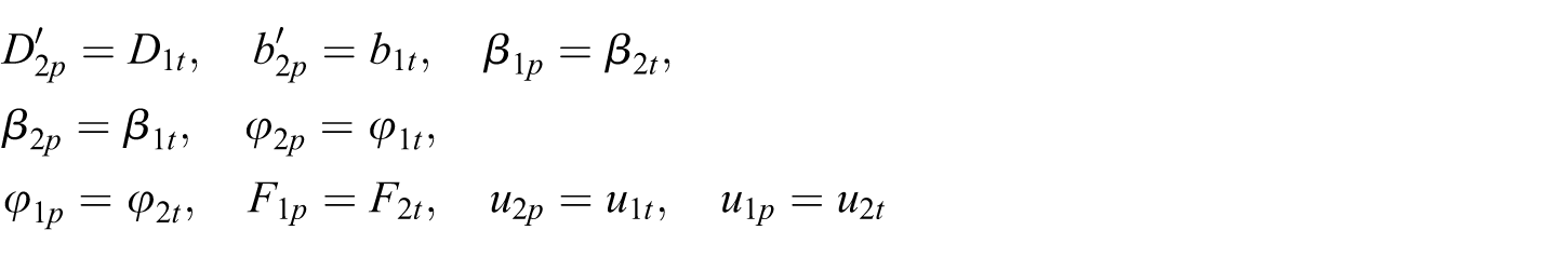
We can show that the water inlet angle to the impeller in the hydraulic turbine is equal to the volute angle. In fact, the volute operates as a guide channel. The water outlet angle from the impeller during turbine operation is equal to the impeller inlet angle during pump operation (assuming no whirl at exit). 9 So, we can consider the same Euler heads for turbine and pump modes at best efficiency point (BEP) after increasing the flow rate 9

Following equations (2), (3), and (4), then
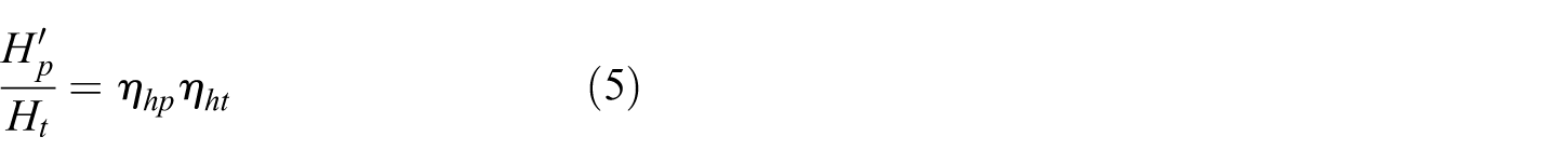
Following equation (5)

Following equation (4)

where
When the centrifugal pump is used as a hydraulic turbine
Assuming that
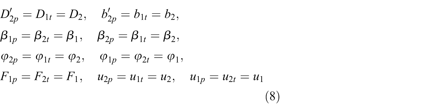
Plugging equation (8) into equation (7)
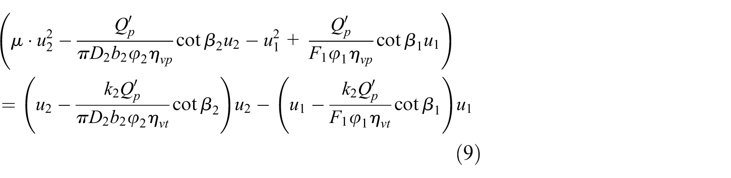
Assuming that

From equation (10)

Plugging equations (6) and (11) into equation (1)

Therefore


where
Equation (13a)–(13c) constitutes the conversion relation of centrifugal pumps as hydraulic turbines on the basis of the amplification coefficient, and they are non-dimensionalize. Because the new conversion relation includes the amplification coefficient of the centrifugal pump, the conversion relation may be used to choose more accurately which centrifugal pump to use as a hydraulic turbine.
Experimental study
Experimental scheme model selection
Three laboratory models were tested in the hydraulic turbine experiment table (Figure 2). The main equipment for the hydraulic turbine experiment table is a feed pump, PAT, energy dissipation pump, torque meter, electromagnetic flowmeter, differential pressure transducer, sluice valve, control valve, bottom valve, and an electromotor. The high-pressure fluid required for the PAT’s energy recovery was supplied by a feed pump. An energy dissipation pump was installed to consume energy generated by the PAT and to regulate its rotational speed.

Hydraulic turbine experiment table.
A torque meter was installed to measure energy generated by the PAT. The discharge was measured by an electromagnetic flowmeter. The PAT’s inlet and outlet pressure was measured by differential pressure transducer. The flow rate of turbine is controlled by control valve. After measuring all parameters, the required pressure head, shaft power, and efficiency were obtained. The uncertainties of the measured required pressure head H, flow rate Q, hydraulic power Ph, generated shaft power P, and efficiency
Centrifugal pumps with specific speeds of 33, 47, and 66 were chosen as the hydraulic turbines in this experiment. The design parameters of these centrifugal pumps are flow rate
Geometric parameters of the centrifugal pumps.


The centrifugal pumps impellers.
Experimental verification
Three centrifugal pumps are used as experimental models in Table 1, and they are allowed to rotate in reverse to act as hydraulic turbines. The new conversion coefficients of the centrifugal pumps as hydraulic turbines containing flow rate amplification coefficients are calculated by substituting the geometric parameters of these centrifugal pumps into equations (6), (11), and (12). After this, we perform an experiment in order to verify the calculation results of the conversion relations containing flow rate amplification coefficients using the hydraulic turbine experiment table shown in Figure 2.
The comparative results of the new conversion coefficients of the centrifugal pumps as hydraulic turbines are obtained using equations (6), (11), and (12); experimental data; the Childs relation; the Hancock relation; the Stepanoff relation; the Sharma relation; the Alatorre-Frenk and Thomas relation; the Schmiedl relation; the Hergt relation; the literature 9 and are listed in Table 2.
Comparison between the calculation results of different conversion relations and experimental data.

New conversion coefficients of the centrifugal pumps as hydraulic turbines are obtained using equations (6), (11), and (12) and are closer to the experimental data than the calculation results using other conversion relations (Table 2); the errors are less than those of the experimental data. The main reason for the error is the assumptions quoted in this article which are obtained from the work by Yang et al., 9 and in addition, the rotation speed of hydraulic turbine is also the cause of error because of the rotation speed of hydraulic turbine is hard to control. Measuring precision of flow rate and pressure is also one of the reasons.
Clearly, we can use the new conversion relation of centrifugal pumps as hydraulic turbines containing the flow rate amplification coefficient to accurately choose which centrifugal pump to use as a hydraulic turbine.
Effect of the amplification coefficient on the conversion coefficient
We know that the conversion relation of centrifugal pumps as hydraulic turbines is indeed connected to the flow rate amplification coefficient and the specific speed amplification coefficient from equation (13a)–(13c). The conversion coefficients when the specific speed is equal to 33 are listed for different amplification coefficients (Table 3).
Conversion coefficients under different amplification coefficients.

Table 3 shows that with an increase in flow rate amplification coefficient, the flow rate conversion coefficient and specific speed conversion coefficient gradually decrease; the effect of flow rate amplification coefficient on the flow rate conversion coefficient is greater; the flow rate amplification coefficient has no effect on the head conversion coefficient. It is clear that the effect of the different amplification coefficients on the conversion coefficient of centrifugal pumps as hydraulic turbines is greater when the centrifugal pump with a low specific speed is designed with the method of increasing the flow rate.
Conclusion
In this article, we obtain a new conversion relation of centrifugal pumps as hydraulic turbines that contains the flow rate amplification coefficient. We found that with an increase in flow rate amplification coefficient, the flow rate conversion coefficient and specific speed conversion coefficient gradually decrease, and the effect of flow rate amplification coefficient on the flow rate conversion coefficient is greater; the flow rate amplification coefficient has no effect on the head conversion coefficient.
We know by research that when centrifugal pumps with low specific speed are designed using the method of increasing the flow rate, there are different flow rate amplification coefficients for the pumps. These different amplification coefficients lead to differences between the optimum conditions after amplification and the optimum design conditions. Therefore, these different flow rate amplification coefficients lead to differences in the conversion coefficients of centrifugal pumps as hydraulic turbines, and the flow rate amplification coefficient is the main reason that calculation results of PAT conversion relations differ between scholars.
Footnotes
Appendix 1
Appendix 2
The model of reference. 8
Academic Editor: Yangmin Li
Declaration of conflicting interests
The author(s) declared no potential conflicts of interest with respect to the research, authorship, and/or publication of this article.
Funding
The author(s) disclosed receipt of the following financial support for the research, authorship, and/or publication of this article: This work was supported by grants from the Education Department Key Project of Sichuan Province of China (17ZA0366), the Nature Science Foundation of China (51279172), China Postdoctoral Science Foundation (2016M600090), the Key Scientific Research Fund of Xihua University of China (Z1510417), and the Open Research Subject of Key Laboratory of Fluid and Power Machinery, Ministry of Education (szjj2016-004).