
Abstract
A lumped parameter model for a vapor bubble–driven valve-less micro-pump is established, in which the mass transition process is considered, and a numerical model is built to validate it. The lumped parameter model consists of a bubble dynamic model based on Rayleigh–Plesset equation, a phase-change model based on thermodynamics, and a pump chamber pressure model derived from the mass conservation law accounting for the resistance of the nozzle and diffuser. The numerical model is established in ANSYS Fluent. Source terms of mass and energy transfers caused by phase change are taken into the control equation using user-defined function. The result shows that these two models have a good agreement with each other, in terms of bubble dynamics and flow performance. The proposed analytical model allows a convenient tool to study the vapor bubble–driven valve-less micro-pump and has a potential to guide the design of the micro-pumps.
Introduction
With the advantages like low power consumption and high integration, micro-pump becomes an important driving component in microfluidic system, 1 which has wide application prospects in biomedical, aerospace, micro-electromechanical system, and environmental monitoring fields. 2 Generally, micro-pumps can operate by means of mechanical displacement,3–5 vapor bubble, 6 electrohydrodynamic, 7 electrocapillary, 8 or magnetic.9,10 Among them, bubble-driven micro-pump has advantages for its easiness of manufacture and potentials to get high efficiency. 11
In 1995, Ozaki 12 heated a single bubble in the pipeline asymmetrically to make the bubble expand in one direction, driving the fluid flow directionally; Jun and Kim 6 used multi-bubble methods in which one bubble acts as a valve and the other one expands to pump the fluid; a plurality of air bubbles needs coordinated work and is difficult to control. In 2002, Tsai and Lin 11 developed a bubble-driven valve-less micro-pump consisting of a diffuser, a nozzle, a pumping chamber, and a heater. In 2006, Jung and Kwak 13 fabricated and tested a similar micro-pump under several conditions. In 2009, Deng 14 established a numerical model for bubble-driven valve-less micro-pump. In 2010, Chan et al. 15 reported another bubble-actuated micro-pump in which the bubble is induced by electrolysis process.
This article focuses on the vapor bubble–driven valve-less micro-pump presented by Tsai. Vapor bubble–driven valve-less micro-pump makes use of evaporation and condensation of gas, combined with the different resistance characteristics of nozzle and diffuser to achieve a net flow. There is not any moving part in this kind of pump, which made it easy to manufacture. Influenced by the bubble dynamics, quality, and impact of the gas–liquid two-phase heat transfer and coupling effect of pump chamber and inlet/outlet resistance characteristics, the current studies of thermal vapor bubble–driven valve-less micro-pump mechanism mainly depends on numerical simulation.16,17 The computational efficiency of the numerical model is low.
In order to carry out more in-depth studies with less computational cost, the lumped parameter approach is chosen as another methodology to understand the operating mechanism for fluidic devices. In 2009, Eames et al. 18 studied valve-less micro-pumps actuated by piezoelectric disks with the lumped parameter model. However, bubble dynamics have to be taken into consideration in the lumped parameter models of bubble-driven valve-less micro-pump. In this article, bubble dynamics model, the gas–liquid two-phase model, and the fluid dynamics model for micro-pump are constructed for the existing micro-pump and integrated into the lumped parameter physical model, to obtain a further theoretical explanation of micro-pump mechanism and to study the effects of different drive parameters, structural parameters, and flow characteristics in micro-pump operating performance. The numerical simulation results are compared to find the validity of the proposed model.
Modeling
Work principle of micro-pump
As shown in Figure 1, the micro-pump consists of three parts: an inlet (diffuser), an outlet (nozzle), and a circular pump chamber. On the bottom of the chamber, a circular heater is attached, driving the liquid by heating periodically.

The structure of the micro-pump.
With the heater heating periodically, the liquid in the pump chamber evaporates and condensates, causing a periodically expansion and contraction of the vapor bubble; thus, the effective volume of the chamber changed.
The diffuser and the nozzle operates as like incomplete one-way valves: when the vapor bubble expands, the liquid flows out of the chamber, and the inlet acts as a nozzle with a relatively bigger resistance, while the outlet acts as a diffuser with a smaller resistance. Therefore, the flow of the outlet is larger than the inlet. However, when the vapor bubble contracts, the liquid flows into the pump chamber, and this time, the inlet acts as a nozzle, and the outlet acts as a diffuser. So, the flow of the outlet is smaller than that of the inlet, thus leading to a net flow toward the outlet.
Lumped parameter model
Pump chamber pressure model
Taking the liquid within the pump chamber as a control volume, when the bubble expands, the pressure in the chamber rises, and the liquid is driven out of the chamber. The inlet acts as a nozzle, while the outlet acts as a diffuser; when the bubble contracts, the pressure in the chamber drops, sucking the liquid into the chamber from outside. The main governing equations for the fluid dynamic model of the control volume consist of the pressure build-up equation derived from the mass conservation law and the flow rate equation derived from Bernoulli law. The pressure derivative of the liquid in the pump chamber is

In equation (1), pc is the pressure of the liquid in the chamber, EL is the bulk modulus of the liquid, Vc is the volume of the chamber, dm is the amount of liquid mass that has phase changed, ρL is the density of the liquid, and dVb is the bubble volume increased. The item stands for the liquid volume decreased due to phase change. Q1 is the inlet flow, and Q2 is the outlet flow.
In the phase-change process, the temperature of the liquid–gas interface is maintained at the boiling point. It is assumed that the temperature throughout the pump is equal since the pump is small.
In the pumping mode, the vapor bubble gets heated and expands. The inlet acts as a nozzle, and the outlet acts as a diffuser (Figure 2).

Flow directions in the pumping mode.
It is assumed that the direction from the inlet to the outlet is positive, from outlet to inlet is negative. The flow of the inlet and outlet can be calculated by the following equations
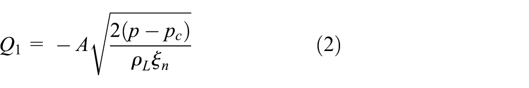

where A is the least area of inlet and outlet, p is the pressure outside the chamber, pc is the pressure in the chamber, ρL is the density of the liquid, ξn is the resistance coefficient of nozzle, and ξd is the resistance coefficient of diffuser. They can be obtained by referring to the previous experimental data. 19
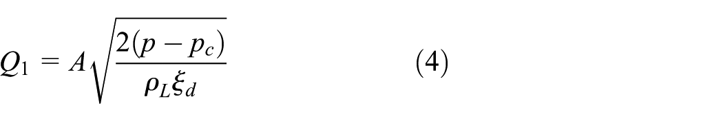
When the vapor bubble is cooled down and contracts, which is called “sucking mode,” the liquid flows into the pump chamber, and this time, the inlet acts as a diffuser, and the outlet acts as a nozzle (Figure 3).

Flow directions in the sucking mode.
In the sucking mode, the flow of the inlet and the outlet can be calculated by the equations below

Bubble dynamics model
Assuming that the bubble is spherical, the volume of the bubble Vb is related to the bubble radius R by

According to the Rayleigh–Plesset equation, the change of R is in accordance with equation (7)

where pb is the pressure in the bubble, σ is the coefficient of the bubble’s surface tension, and µ is the viscosity of the liquid.
Phase-change model
Ignoring the heat dissipation, according to the first law of thermodynamics, the energy input is totally used in two ways: the evaporation of the liquid and the expansion of the gas

where P is the heating power and hL is the latent heat of vaporization of the liquid.
For vapor, by ideal gas state equation, there is

Derivate the total differential of both sides, note that phase changing is an isothermal process, so dT = 0

Numerical model
A numerical model based on finite volume method is established to test and verify the lumped parameter model.
To simulate this process, the multiphase model in software Fluent is taken into account. The gas–liquid boundary is caught by volume of fluid method (VOF). The surface tension is calculated by the continuous surface force model which was established by Brackbill et al. 20
According to the evaporation–condensation model established by Lee, 21 when the temperature is higher than the saturation temperature, the liquid evaporates, absorbing heat, and the temperature drops. When the temperature is lower than the saturation temperature, the vapor condenses, and the temperature rises. If a proper evaporation/condensation frequency is chosen, the temperature will converge to the saturation temperature, thus assuring the temperature near the vapor–liquid boundary is close to the saturation temperature. The principle of choosing the evaporation/condensation frequency is: if a deviation from the saturation temperature is observed on the vapor–liquid boundary, the evaporation/condensation frequency should be increased. If convergence difficulties occur, the evaporation/condensation frequency should be decreased. In this case, the evaporation frequency is 800 Hz, and the condensation frequency is 9000 Hz.
A structured hexahedral mesh model is drawn with ICEM-computational fluid dynamics (CFD), according to grid independence test (Table 1); when there are 133,255 nodes, the average flow becomes stable.
Grid independence test.

The time step is 1 × 10⁻⁶ s. Assume that the fluid in the chamber is laminar flow, since the Reynolds number is small. 14 The first-order implicit unsteady noncoupled solution is chosen in the solver. The pressure implicit with splitting of operator (PISO) algorithm is applied to the coupling of pressure and velocity. The second-order upwind differential discretization scheme is adopted for the momentum equation. The first-order upwind differential discretization scheme is used for the energy equation (Figure 4).

3D mesh of the valve-less micro-pump.
Structure and parameters
Fluid properties
Methanol, whose thermodynamic property is shown in Table 2, is taken as the working fluid for its ability to evaporate at a relatively low temperature.
Properties of working fluid.

Geometry parameters
The geometry parameters of the valve-less micro-pump are shown in Table 3. The positions of the dimensions are presented in Figure 5.
Geometric parameters of the valve-less micro-pump.

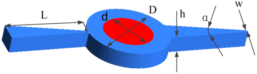
Geometric dimensions of the valve-less micro-pump.
Heating strategy
In order to assure a continuous operation, the heat absorbed by the pump in each heating cycle should be equal to the heat radiated. Assuming the heat power of the heater while heating is P1, the heat power of the heater while cooling is P2, and the heat proportional to each period is k. Equation (11) should be satisfied

In the lumped parameter model, heating transportation is not taken into consideration, which means the temperature of the pump chamber is kept at 337°C (the saturation temperature of methanol), and all the heat absorbed by the bubble will immediately act on the liquid–gas surface. However, in practice, it takes quite a while transporting the heat from the heater to the bubble surface or the other way around. As a result, a noticeable lag of flow rate changing can be observed in the numerical model, which was ignored by the lumped parameter model. In order to simulate the effects of this lag, the heating fluxes q1 and q2 should be multiplied by a correction factor c. In this instance, c = 0.8. The heating frequency is 250 Hz, and the heat proportion k in every heating cycle is 0.1.
Boundary conditions
The boundary condition of the inlet is pressure inlet and that of the outlet is pressure outlet. The gauge pressure is 0 Pa, and the temperature is 337 K. While heating, the heater is set to a constant heat flux of 1 × 10⁶ W/m2. While cooling, the heat flux is −1.11 × 10⁵ W/m2. On other boundaries, adiabatic condition is utilized. An initial bubble with a radius of 2 × 10⁻⁴ m is set at the center of the chamber to accelerate the convergence.
Results and discussion
The results are shown as follows. Figure 6 shows that the trend of the bubble radius calculated by these two models is the same, while the derivation of the values between these models can be observed. The reason is that in the lumped parameter model, it is supposed that the temperature in the chamber is kept at saturation temperature, so that all the heat absorbed contributes to phase change. However, in the numerical model, some of the heat is stored in superheated gas, so the amount of phase change is less in this model, which leads to a smaller bubble.

Comparison of bubble radius calculated by the two models.
In Figure 7, it can be observed that the temperature in the pump chamber is not distributed uniformly. Vapor inside the bubble is overheated, which stores a lot of energy.
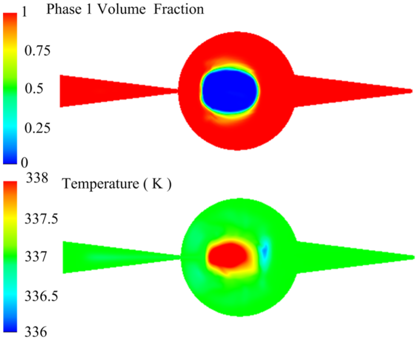
Phase fraction and temperature in the micro-pump.
It can be obtained from Figure 8 that the flow rate of the numerical model has a significant lag effect with respect to the heating and cooling process since it takes the heat transfer process into account. However, it can still be noticed that the main trend of the flow rates is identical. In this condition, the average flow rate calculated by the lumped parameter model is 76.88 µL/min, while the result of the numerical model is 71.28 µL/min. The accuracy is acceptable. Besides, the lumped parameter model can also be used to predict the pressure in the pump chamber and the flow rate of the inlet and the outlet.

Comparison of flow rates calculated by the two models.
It can be seen in Figure 9 that the pressures in the bubble and the pump chamber are fairly close to each other during the heating and cooling processes, which is probably due to a relatively small resistance of the inlet and outlet and low surface tension of the bubble.
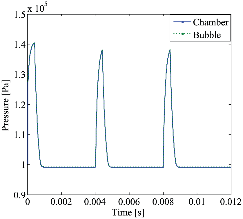
Pressure of bubble and pump chamber.
Figure 10 shows the result of the flow rate at the inlet and the outlet ports. It can be seen that the fluid flows in the opposite direction. Most of the flows can be offset from each other, and the part which is not offset makes up the net flow. Additionally, it should be noted that the flow provided by the micro-pump is not continuous.

Flow rate of the inlet and outlet.
In the end, it is worth mentioning that the structure of the nozzle and diffuser, the heating frequency, and the heating power could have significant influences on the pump performance, including the flow rate and efficiency, which represent the further study of this subject.
Conclusion
In this work, a compact model for the vapor-driven valve-less micro-pump focusing on the bubble dynamics and flow features in the lumped parameter approach is presented. The model considering both the mass and heat transfers is compared to a numerical model to show its effectiveness. It turns out that the lumped parameter model established in this article has a good agreement with the numerical model, showing that it has a good potential to guide the design of the micro-pumps. For future work, experimental work will be conducted to validate and improve the model, and studies on the performance of micro-pumps affected by different factors such as heating power, driving frequency and angle of the nozzle and the diffuser can be performed using this model.
Footnotes
Appendix 1
Academic Editor: Xiaotun Qiu
Declaration of conflicting interests
The author(s) declared no potential conflicts of interest with respect to the research, authorship, and/or publication of this article.
Funding
The author(s) disclosed receipt of the following financial support for the research, authorship, and/or publication of this article: The authors would like to acknowledge the financial support from the National Science Foundation of China (grant no. 51505030) and the Fundamental Research Funding of Beijing Institute of Technology.