
Abstract
There are very few attempts to explore the erosion-wear behaviour of the Cr3C2–NiCr coating deposited on the nickel-based superalloy employed to resist the solid particle erosion damages for flue gas turbine blade. This work focuses on the erosion mechanism of Cr3C2–NiCr coating under service conditions. A
Keywords
Introduction
Solid particle erosion is a common mode of material degradation in many industries such as petroleum, chemical, aerospace, and power generation, which caused great economic losses. The flue gas turbine is one of the important energy-saving equipments in petrochemical enterprise. Ni-based superalloys have been most widely applied in modern turbine blades due to their excellent mechanical properties.1–3 However, the catalyst particle of high-temperature flue gas can cause serious erosion wear to the turbine blades which leads to the degradation of the fatigue performance. 4
To prolong the service life of the components, several coating techniques are used to improve the erosion resistance of materials in that high-velocity oxygen-fuel (HVOF) spraying have attracted significant attention. It is evident from literature that coating techniques have played an increasingly important role in reduction of erosion damage.5–7 The purpose of this kind of coating is to insulate or protect the component from aggressive environments and thereby enhancing the service life of the substrate material. For example, Cr3C2–NiCr cermet coating was widely used in high-power machine blade for the virtues of high hardness, low friction coefficient and wear resistance. 8 This coating has high thermal stability, oxidation resistance and corrosion resistance at 500°C–900°C. Therefore, as one of the best high-temperature wear-resistant coatings, it is widely used in high-temperature abrasion, corrosion or erosion work condition parts.8–10
At present, the wear resistance and corrosion resistance of the Cr3C2–NiCr cermet coating were studied widely. Many investigations5,6,8,9–15 revealed that erosion-wear resistance properties of the coating are mainly related to the structure of coating, erosion particle and erosion condition which characterized the erosion behaviour of Cr3C2–NiCr-based coatings. Although many researchers have studied the solid particle erosion properties of Cr3C2–NiCr cermet coating, these were limited to simple erosion tests without taking into account the influence of the service conditions such as impingement angle, erosion temperature and particle size. There are only fewer attempts to explore the erosion resistance of the Cr3C2–NiCr coating deposited on the substrate material of nickel-based superalloy. Nickel-based superalloy is typically employed to resist the combined erosion corrosion damages when the service temperature is above 600°C for flue gas turbine blade, and the performance of superalloys associated with the coating is always a concern.
This study focuses on Cr3C2–NiCr coating used for the flue gas turbine blade. Cr3C2 powder is mixed with NiCr powder, and HVOF spraying is used to form the composite coating deposited on the nickel-based superalloy substrate for possible applications in gas turbine blade repair. The erosion behaviour of coating is studied according to different erosion conditions based on its service environment, and the influences of erosion parameters and erosion mechanism are investigated. But few have been performed at high temperature.
Experimental details
Coating preparation
GH738 made for blades were usually employed to resist mechanical fatigue which fulfils good mechanical properties such as high tensile and yield strength, and significant rupture strengths. In this study, GH738 was chosen as the substrate material. The chemical composition of the substrate materials in wt% is as follows – Cr: 19.21, Ti: 2.97, Mo: 4.42, C: 0.048, Al: 1.39 and Ni: balance. 3
The substrate samples with dimensions of approximately 30 mm × 25 mm × 3 mm were prepared and grinded with 800-grit SiC sand papers, and the samples were grit blasted with corundum before spraying of the coatings by HVOF process. The grit blasting can improve the mechanical interlocking between the coating and the substrate. Specimens were prepared manually, and all care was taken for any structural changes in the specimens.
The agglomerated and sintered Cr3C2–25NiCr powder (nominal size: −45/+15 µm) provided by the Corrosion and Protection Center, University of Science and Technology Beijing, were used as feedstock alloys for HVOF spraying process in the study. SEM micrograph is shown in Figure 1 for Cr3C2–25NiCr powder which verifies the grain size and the shape of the alloy powders. Figure 2 shows the X-ray diffraction pattern for the received powder.

SEM micrograph of Cr3C2–NiCr powder.
X-ray diffraction patterns of Cr3C2–NiCr powder.
HVOF process parameters
The HVOF spray experiments were carried out with a commercial HVOF (STR-3000) thermal spray system (Corrosion and Protection Center, University of Science and Technology Beijing, Beijing), which was performed using kerosene as the fuel gas and argon as the powder carrier gas. The process parameters employed for HVOF spray process are listed in Table 1, and the parameters used in the spraying process are kept constant throughout the experiment.
Spray parameters employed for HVOF process.

HVOF: high-velocity oxygen-fuel.
The average as-sprayed coating thickness deposited on the substrates was about 40–160 µm by 1–4 passes of spraying. The HVOF spray parameters used could provide coatings of desired thickness range. Coating thickness was measured from the back scattered image obtained along the cross section of coated specimen.
Erosion testing conditions
The erosion tests were conducted using the high-temperature gas–solid two-phase flow erosion testing machine available with the China University of Geosciences (Beijing) as shown in Figure 3(a), and the principle diagram of the machine is shown in Figure 3(b). The silica erodent particles were used for this study. The microstructures were observed and analysed using scanning electron microscopy (SEM) of SHIMADZU SSX-550. The SEM image is shown in Figure 4, which shows a flaky and angular morphology.
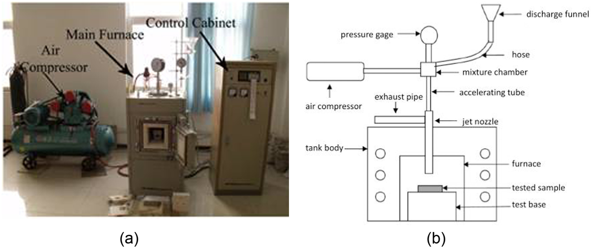
High-temperature solid particle erosion abrasion tester: (a) photograph and (b) principle diagram.

SEM morphology of erosion particles.
The flux rate of impact particles was 100 g/min based on the experience. Each test was carried out for about 5 min. During the test, the sample surface would be impacted with 500 g of black SiO2 erosion particles. The distance from the spray nozzle to coating surface was 100 mm. The erosion testing parameters were as follows.
The above coated samples were polished to give an average coating thickness of 160, 140, 120, 100, 80, 60 and 40 µm, respectively. The impingement angles of erosion particle stream on the samples were 30°, 60° and 90°, respectively; the samples were impacted at various temperatures (400°C, 500°C and 600°C); the pressure of compressed air was, respectively, 0.2, 0.25, 0.3, 0.35, 0.4, 0.45 and 0.5 MPa; and the silicon oxide particle size was, respectively, 100, 120, 150 and 280 mesh.
Measurement of erosion rate
Solid particle erosion resistance was characterized with volume erosion rate, which was defined as the volume loss of sample divided by the mass of erosion particles (mm3/g) and expressed by equation (1)16,17

where
The eroded specimens were cleaned with ultrasonic wave and dried; then, they were weighed with an analytical balance. 17 The erosion testing was carried out three times for each erosion condition to ensure the repeatability of the test and the average value was reported.
Results and analysis
Characterization of coating
The photograph of the Cr3C2–NiCr coated GH738 sample is shown in Figure 5. The hole in the sample as shown in Figure 5 was machined in order to be fixed in the HVOF spray process. Before erosion testing, the surface of coating sample was given metallographic grinding with 1200-grit sand paper. Furthermore, it was polished by grinding paste. Polishing samples were cleaned in ethanol for 5 min with ultrasonic cleaning until the surface is smooth without blemish. Microstructure of Cr3C2–NiCr cermet coating was observed by SEM analysis of SHIMADZU SSX-550. Coating surface and the polished cross-sectional microstructure of the as-sprayed coating are shown in Figure 6. No voids were observed at the coating substrate interface, indicating good adherence between coating and substrates.

Photograph of the coated GH738 samples subjected to erosion.

SEM microstructure of coating: (a) coating surface and (b) cross section.
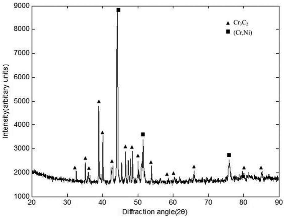
The X-ray diffraction pattern of the Cr3C2–25NiCr as-sprayed coating is shown in Figure 7. A great peak characteristic of a substantial amount of Cr3C2, Cr7C3 (Ni, Cr) solid solution phase is observed. The intensity of oxide was not detected due to the high temperature during HVOF process.

X-ray diffraction patterns of as-sprayed coating.
In addition, the micro-hardness of the coating and the substrate were measured by the micro-hardness tester. Test conditions: applied loads were 9.807, 4.903, 2.942 and 1.961 N; loading time: 10 s. The results showed that the Vickers hardness of the coating layer is about 680–950 HV, and the matrix hardness is approximately 300–400 HV. Obviously, the hardness value of coating is about two times that of the substrate. This indicates that some spray coating materials can greatly increase the surface hardness of the parts, and erosion-wear resistance performance increases along with the increase in hardness.
Surface microstructure of the coating
Erosion-wear behaviours of the same sample for 300 and 500 g impact particles with the 90° impact angle at room temperature were observed in the scanning electron microscope. The surface morphology of the coating after solid particle impact erosion is shown in Figure 8(a) and (b). It can be seen from Figure 8 that compared with Figure 6(a), the wear occurred on the coating surface after erosion.
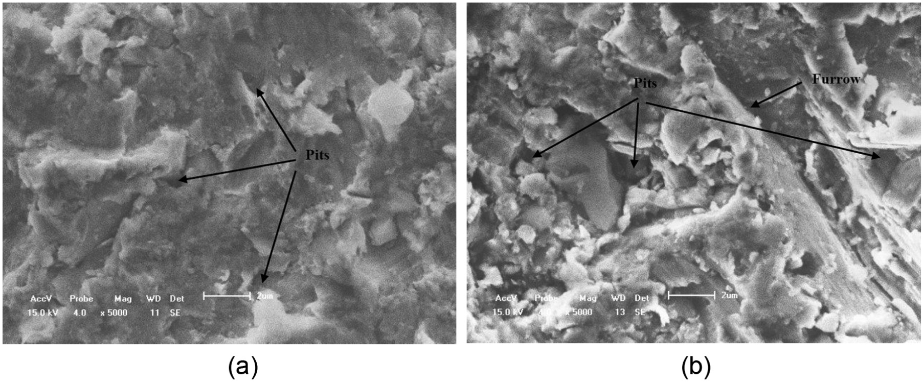
Coating surface microstructure after erosion with different mass particles: (a) 300 g erosion particles and (b) 500 g erosion particles.
There have been a large number of pits and furrows. With the increase in the number of erosion particles, the impact occurs repeatedly. Plastic deformation can occur and accumulate. When the stress exceeds the material plastic limit, crack will initiate and expand continually. Eventually, it will flake in the form of the coating debris. In addition, the damaged area of erosion surface also grows, with gradually deepened pit depth.
Effect of air pressure
Figure 9 shows the volume wear rate of coating material at different air pressure which means that the impact velocity differs due to the air pressure. For this erosion testing, the coating thickness was 120 µm and the specimen was impacted with the 90° impact angle at room temperature (particle size: 150 grade mesh).
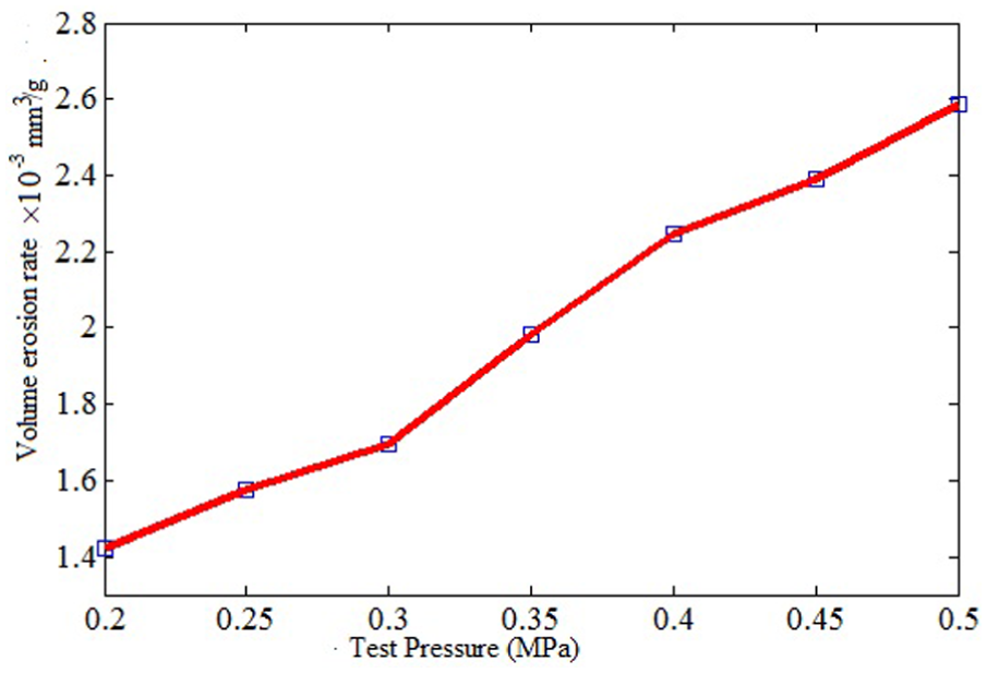
Volume erosion rate of coating material versus air pressure.
As can be seen from Figure 9, the volume erosion rate of the specimen increased gradually with the increase in air pressure. The phenomenon can be interpreted as follows: the impact velocities increase gradually with increasing air pressure, thereby leading to the larger area of cutting peeling. Accordingly, the number of etch pits and its depth increased gradually. It is likely consistent with the simulation results of literature. 18 Also, it can be interpreted by the empirical formula expressed by equation (2), and the erosive wear quality was mainly determined by the kinetic energy of the particles 19


where
Effect of coating thickness
According to the conclusions from previous research results, 18 coating damage is serious when the coating layer thickness is thinner. In engineering practice, the average thickness of C-33 metal-ceramic coating that is widely used in high-power gas turbines is about 120–150 µm. Therefore, the effects of coating thickness were investigated. Figure 10 shows the volume wear rate of coating for different coating thickness. Wherein, experiments were carried out at room temperature with the impact angle of 90°. The pressure of compressed air was 0.4 MPa, and the size of silica particles was uniformly selected to 150 mesh (500 g).
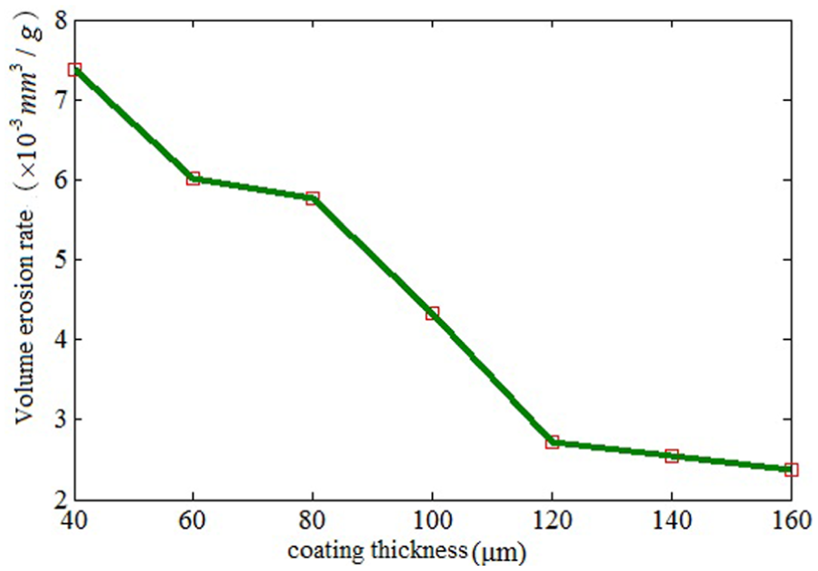
Volume erosion rate of coating material versus coating thickness.
As can be seen from Figure 10, the volume wear rates of coating material increase with the decrease in coating thickness. Especially, for the thinner coating, the wear phenomenon is more serious. Furthermore, partial coating material will be detached and removed from the substrate material and could not protect the substrate. The conclusions agree qualitatively with the coating performance observed numerical simulation. 18
Testing results show that the wear rate of the coating material was only negligible variation in the erosion rate of the coating when the coating thickness was more than 120 µm. Therefore, in practical engineering, reasonable coating thickness can improve the service life of parts.
Effect of impact angle on erosion
Figure 11 shows the effect of impingement angle on the volume erosion rates of composite coating. These tests were conducted with the coating thickness of 120 µm at room temperature, 0.4 MPa air pressure and 150 mesh particles.

Volume erosion rate of coating material versus erosion angle.
It can be seen from Figure 8 that the volume erosion rate largely relies on the impingement angle. The erosion rate at 30° impact angle (for typical plastic material erosion mechanism19,20) is higher than that of 90° (for typical brittle erosion mechanism19,20) but lower than that of 60°. From the beginning, the coating presents a brittle property which means the erosion behaviour is similar to that of brittle ceramic material, so with the increase in the impact angle, the erosion rate increases. But the microcutting predominantly occurred in the relatively soft NiCr binder phase, which will result in the harder particles being exposed by the impact of particles, then cause subsequent cutting. The shielding effect of the Cr3C2 particle reduces, and the accumulation of dislocation in the weak bonding boundary of the Cr3C2 particles accelerated their pullingout. Therefore, in the impact angle 90°, the erosion is less instead.
During tests process, no evident cracks were observed in eroded sample according to SEM photos. In addition to the presence of impact craters, plough and different forms of cutting wear were also generated. The presence of furrows and lips indicates the material removal by microcutting and microploughing action. Coating shows better erosion resistance at 90° impact angle as compared to 30° impact angle. So, it can be concluded that the Cr3C2–NiCr samples exhibit the combined mode of erosion mechanism (i.e. ductile and brittle), and the brittle mode of erosion characteristic may prevail. The irregularity of particle shape may also contribute to this phenomenon. When polygon rigid particles impacted target material with a certain angle, impact force is decomposed into a force of vertical and horizontal directions.
As stated in literatures,20,21 the material removal is mainly due to the microcutting action of the erodent particle at a low impact angle, but when at high impact angle, the material removal is dominated by the lip formation, strain hardening of lips and subsequent ductile fracture of these lips. This similar phenomenon of the combined mode of erosion mechanism for coating materials was observed during the study of erosion-wear mechanism of NiCrSiB/Al2O3 by Praveen et al. 21
Effect of erosion temperature
In application, Cr3C2–NiCr coating is often designed for wear applications at elevated temperatures. Now there is an increasing interest about the wear behaviour at high-temperature environment. For example, according to the literatures,14,15 HVOF-sprayed 75Cr3C2–25NiCr coatings were found useful in providing necessary resistance to boiler steel or nickel-based superalloy against corrosion at 750°C and 900°C. But few investigations of solid particle erosion at high temperature were studied. So, the effect of temperature on the erosion mechanism of Cr3C2–NiCr coating on nickel-based superalloy was studied.
Figure 12 shows the effect of erosion temperature (400°C, 500°C and 600°C) on the eroded surfaces of samples at the impingement angle of 90°. As shown in Figure 10, the volume erosion rates of composite coating decrease with the increase in the erosion temperature, and the maximum and minimum volume erosion rates occur at 400°C and 600°C, respectively.

Volume erosion rate of coating material versus erosion temperature.
The phenomenon can be interpreted that when the eroded temperature was higher than 400°C, the plastic properties of the coating increase with the increase in temperature. Along with the erosion, the plastic deformation occurred, in which the material wear takes place mainly by microcutting. So, the volume erosion rate decreases at the impingement angle of 90°. At low temperature, the coating tends to show brittle material property, so the volume erosion rate is higher due to impingement angle of 90°. In fact, the volume erosion rate can be significantly affected by the temperature.
However, this may be that when the erosion temperature rises above 400°C, the material starts to oxidize which could improve the wear resistance of materials. Also, coarse aggregate on the surface of materials expanded, and the bonding strength between coarse aggregate and matrix was enhanced. The plastic deformation can improve the wear resistance of materials during the erosion at high temperatures. Similar conclusion was obtained by Li et al. 17 The coating may be more suitable for use in relative high-temperature conditions. This was identical to the hot corrosion behaviour at high temperature of Cr3C2–NiCr.14,15 The literatures14,15 indicated that the coatings can enhance high-temperature corrosion resistance, whereas the uncoated substrates experienced higher weight gain. But the erosion mechanism of Cr3C2–NiCr coating on nickel-based superalloy at different temperatures is more complicated which may involve many factors. Therefore, further tests and simulations will be conducted for the future.
Effect of particle size
The effects of particle size on the volume erosion rates of composite coating were studied. These tests were conducted with the coating thickness of 120 µm at room temperature, with 0.4 MPa air pressure and 90° erosion angle.
Experimental results of the relationship between volume erosion rate and particle size are shown in Figure 13. It can be seen that with the increase in the particle size, the volume erosion rates of the coating material increase, and there is a large difference due to the different particle sizes. Such observations may be associated with the kinetic energy of erosion according to empirical formula expressed by equation (1).
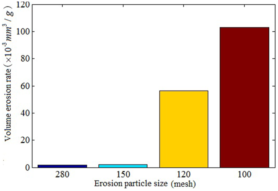
Volume erosion rate of coating material versus erosion particle size.
The experimental results are not very inconsistent with previous results of numerical calculations. 18 According to the simulation results, 18 erosion wear will not notably increase if the size of the particles is more than 60 µm. The difference may be due to the factors, for example, the particle shape and the irregularity are not taken into account in the numerical simulation which assumed that the particle is ideal spherical shape. Also, the material properties of the coated sample and erodent particles are not ideal as described in the simulation. The erosion could also be affected by the particle concentrations. Further tests and simulations will be conducted for future research.
Conclusion
Nickel-based superalloy is mainly used to resist the erosion damage at high temperature. Cr3C2–NiCr coating on the GH738 substrate material was prepared by HVOF spraying process. The erosion test results indicate that the volume erosion rate of the specimen increases gradually with the increase in the air pressure. Also, the number and depth of the etch pits on coating surface increases.
The volume wear rates of the coating material increase with the decrease in the coating thickness, and the wear rate of the coating material has only negligible variation in the erosion rate of the coating when the coating thickness is above 120 µm. Coating shows better erosion resistance at 90° impact angle as compared to 30° impact angle. Also, the maximum volume erosion rate occurs at the impact angle of 60°. So, the mechanism of Cr3C2–NiCr samples is the combined mode of erosion mechanism (i.e. ductile and brittle), and the ductile mode of erosion characteristic dominates.
The results showed that the coating may be more suitable for use in relative high-temperature conditions. The volume erosion rates of composite coating decrease with the increase in the erosion temperature. This may be related to the occurrence of plastic deformation and oxidation protection at high temperature. With the increase in the particle size, the volume erosion rates of the coating material increase. Erosion particle size and shape are the key factors that influence the erosion-wear behaviour.
Footnotes
Academic Editor: Michal Kuciej
Declaration of conflicting interests
The author(s) declared no potential conflicts of interest with respect to the research, authorship, and/or publication of this article.
Funding
The author(s) disclosed receipt of the following financial support for the research, authorship, and/or publication of this article: The research was supported by the Beijing Municipal Commission of Education (grant no. KM201210017005), The Training Programme for Excellent Young Teachers of Beijing Institute of Petrochemical Technology and Scientific Research Promotion Program of Beijing Institute of Petrochemical Technology (grant nos 14031821003/37 and 15031862005/47).