
Abstract
In this study, three webcams are applied to a five-joint robotic arm system. One camera is applied to recognize commands from control panel, which consist of words and numbers. The letters of command can be obtained after image is transformed from red, green, and blue to hue, saturation, and lightness color space and using the optical character recognition and pattern matching process. The message will then be sent to robot system. Another two cameras are used for catching the left and right images of an object. Calibration procedure of the robot and cameras is performed first. The values from image plane can be compared and transformed to three-dimensional coordinates by the Q matrix. The coordinates are then translated to 4096 precision values in robotic arm system. Movements of the robotic arm are based on fuzzy logic theory that can drive the robotic arm to the relative point and position of a given object. Feedback values of arm movement are applied to correct the position error in real time. The robot system can catch the three-dimensional coordinates of the object and perform smartphone automatic testing operations by the commands from visual recognition system.
Introduction
Advance technologies change human life and habit persistently. Routine works and some tasks by manpower have been replaced by new technologies. The automatic mechanism and independent robotic arm or high-technology robot have been used in our daily life, such as auto parking system and robotic surgery system. These are all from different types of technologies. For instance, stereo vision by linear triangulation (LT) algorithm was used in space robotics assembly operations, 1 standard three-dimensional (3D) reconstruction methods were applied to challenging underwater tasks, 2 a new method was presented to control a robotic arm in 3D space without any calibration, 3 or a model similar with human’s arm was created. 4 The 3D coordinates of the target object are essential information for those works. How to acquire object information became one of the main issues in similar researches. In addition to the vision system, position control of a robotic arm is another topic need to be solved. A two-phase trajectory prediction algorithm based on high-speed visual feedback to improve the performance of visual perception and stroke motion control in Ping-Pong robot was developed. 5 In the Ping-Pong robot system, a multi-thread segmentation algorithm was applied to detect the ball by a stereo vision system. The high-speed vision system achieved a good performance with a successful rate of 96% for ball detection. In addition, an adaptive path planning algorithm was developed for robot motion control based on the contentiously updated ball position. The ball positions after bouncing off the table were utilized for motion estimation and path planning. The error in the determinations of hitting position and hitting instant was very small, which resulted with high successful rate. In our study, high-speed vision system and dynamic object position estimation are not required. We utilized much cheaper cameras in system setup. The main effort of our study in image processing is pattern and character recognition. Since the size of character on a smartphone is kind of small, precision positional control with automatic-adjust process to the robotic arm is required in our study, which makes this article differ from other papers.
The robotic arms are very common for test house, assembly line, and company for wafer in dealing with hundreds of thousands repeat operations. For those tasks requiring accurate response that is performed by the robotic arm is in demand. The main purpose of this study is to design an automatic control system, which is able to receive the message/command from the testing system, recognize the position and coordinates, and complete predefined action by a robotic arm to touch desired object. The idea is from a testing house. Engineers in testing house need to focus the testing and wait for message/command from system all day, and most of them are routine works, such as answer phone call, dial number, or turn on/off smartphone. It is inconvenient and tired for engineers doing such routine works daily. In this study, the control system has two webcams that are applied for completing sample calibration by the vision development module of LabVIEW 2012 software6,7 in the first step. In the second step, the 3D stereo coordinates8–10 are obtained by the Q matrix translation.11–13 Another webcam is used for visual recognition, and the image processing uses the optical character recognition (OCR) 7 to recognize the word and match pattern for catching some specified patterns after the image is transformed from the red, green, and blue (RGB) to the hue, saturation, and lightness (HSL) color space. An image of a target is affected by the light source, and the image in the RGB color space is transformed to the HSL color space which can significantly reduce the impact of lightness. Furthermore, pattern matching and character recognition are also applied in this study, 14 both of them use National Instruments Vision Assistant (NIVA) to achieve the specified functions. 7 NIVA allows one to easily configure and benchmark a sequence of visual assistant steps as well. In this study, the NIVA is necessary for vision process, including stereo, image process, OCR, pattern matching, and edge detection. Robotic arm uses these methods to perform the position control.
For robot control, fuzzy theory is applied to set up control rules. The 3D coordinates of a reference position are translated to precision values of the robot system. The 3D information of a target is obtained by two cameras which work as two eyes of robotic arm. The robotic arm can be moved to touch specified points on a target by the 3D information from these two eyes. The control method is very easy and is similar to human’s act, such as touching a target, observing an object, determining position, and orientation of an object. The control scheme can calculate relative distance between robot and object and move robot to touch or pick up object. Human-specific camera vision has been the theme of scientific research for years. From the formation of human binocular disparity, it gradually turned to render 3D structure to two-dimensional (2D) plane and then to develop the use of the principle of focus to “Fuzzy” 3D images. The 3D vision 7 is now appearing in a variety of machine automation applications. There are several ways to calculate depth information using 2D camera sensors or other optical sensing technologies. Here, we use the “Stereo Vision” due to its low cost and easy implementation. The “Stereo Vision” is similar to how our brains work to visually measure distance and acquire the overlapping images of a single region of interest within a scene. Here, we also need to consider “Binocular disparity”; it is because the human eyes focus on one side, compared to most other animals, at the expense of visual range, but has the ability to judge depth and distance. The average distance between the eyes is about 6.5 cm, which is the limit that the eyes can see an object clearly. The left and right eyes can see the image with different phenomenon, called binocular disparity. The clear degree of objects related to the closer the more significant aberration is and the smaller the farther away it is. In this article, the proposed control system can calculate different relative positions with respect to the reference position. The control system has the feedback information of each servo motor, and it can improve the robotic arm to have better accuracy and be able to touch smaller object. In the case of miss touching, automatic-adjust process of the control system can correct the location of the robotic arm automatically. The robot can execute operations that are requested. In this study, an automatic smartphone test system is successfully set up to perform routine works, and it can save human resource a lot.
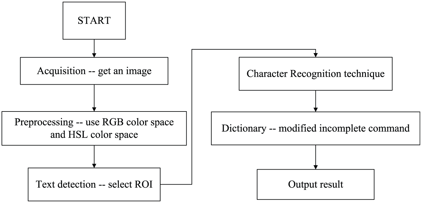
System description
Hardware description
In this study, the controller of embedded computer, robotic arm, and webcams are the main components of hardware configuration. The testbed with a tested smartphone is shown in Figure 1(a). The Dynamixel MX-28 servo motor, which is produced by ROBOTICS Company, is the main motive force of the robotic arm, as shown in Figure 1(b). The motor’s weight is 72 g. Dimension is 35.6 mm × 50.6 mm × 35.5 mm. Resolution is 0.088°, running degree is 0°–360°, and gear reduction ratio is 193:1. Stall torque is 24 kgf cm (at 12 V, 1.5 A). No load speed is 54 r/min (at 12 V). The webcam is the Microsoft LifeCam Studio 1080P Full-HD for OCR recognition and 3D stereo image process. Servo motor uses the proportional–integral–derivative (PID) controller as a main control method, as shown in Figure 2. Kp gain refers to the value of proportional band. Ki gain refers to the value of integral action. Kd gain refers to the value of derivative action. The gain values are between 0 and 254.

(a) Testbed with a tested smartphone and (b) robotic arm with Dynamixel MX-28 servo motors.

PID control of the servo motor.
OCR with image process
The human eyes can feel light, which is called visible light. The range of visual light’s wavelength is about 400–700 nm. A color model is a mathematical model describing the way colors can be represented as tuples of numbers, typically as three or four values of color components. The primary colors of pigment can create a wide range of colors. The pigments are magenta, cyan, yellow, and black. There are many possible color spaces by these colors. For example, when colors are displayed on a computer monitor, they are usually defined in the RGB color space. In this article, the HSL color space is used. 15 The way of making the colors is to use their HSL. Hue describes where that color is found in the color spectrum and the shade of color. Red, yellow, and purple are words that describe hue. The saturation describes how pure the hue is with respect to a white reference. Saturation is a percentage that ranges from 0 to 100. A pure red that has no white is 100% saturated. Intensity, like lightness, is a subjective descriptor that is practically impossible to measure. It embodies the achromatic notion of intensity and is a key factor in describing color sensation. The HSL color of external light can improve the identifiable rate of color and the speed of image process. 16
Figure 3 shows the HSL model based on color circles. The circles are perpendicular to the vertical intensity axis. The RGB color space values are transferred to the HSL color space values by the following equations


The HSL color model based on circular system.
We can use the Match Pattern to quickly locate known reference in the image. Even the location, orientation, lighting, and temperature change of the image will not be affected. We can create a sample model of the object that we want to search and then look for this sample and calculate the similarity of each image. The model is called a template and should be an ideal representation of the pattern or object. If the similarity measure is large enough, we can assume that the object is present. Similarity measure is based on the Euclidean distance. We can compute the cross-correlation function from the similarity measure. The similarity measure based on Euclidean distance method is described below. 16 I(x, y) is the common measure employed when comparing the similarity of the two images (e.g. the template p(x, y) and the test image f(x, y)). It is the metric based on the standard Euclidean distance between two sectors, as shown in Figure 4


Match pattern.
The normalized cross-correlation (NCC) is a process used for finding incidences of a pattern or object within an image. NCC made use of product concept (6); it may be scaled so that it lies in the range of 0–1. When R is equal to 1, this represents p(x, y) is equal to f(x, y).

The OCR here is a machine vision application from NI 2012 software, and the procedure of image recognition is shown in Figure 5. A test environment of original RGB image for OCR is shown in Figure 6. The indication from the monitor is caught by a webcam under a colorful space. It is hard to get rid of the noise or stripe noise from the object, so converting color from RGB image to HSL color space is needed. The OCR provides reading text/characters and numbers from an image for HSL color space, as shown in Figure 7.
The procedure of image recognition technique.

Original RGB image of a test environment.

Processed image in HSL color space by the use of OCR.
Additionally, the robotic arm should be supported with the ability to know whether it can press the correct button or not. We use character recognition and more image processes for poor contrast in small screen on a smartphone to confirm whether the pressed button is the desired button. Figure 8 shows how to deal with the image with different image processes and obtain the words by the OCR in Figure 26. We can check that Figure 8(a) shows the numbers that cannot be recognized in HSL color space with an area of green rectangle. Thus, more image processes are needed. At first, we use the auto threshold: moments, as in Figure 8(b), from NIVA which is suitable for images that have poor contrast. The moments method is based on the hypothesis that the observed image is blurred version of the theoretically binary original; also, we can see which part is dark, which is bright, and whether any noise exist or not. After this, we use the reverse process as in Figure 8(c). From this image we can easily see that the contrast between background and number now is opposite but still not clear and not enough in contrast. We use the reverse again, as in Figure 8(d), and make the image smooth by the equalizer process as in Figure 8(e). Finally, we use the reverse again and obtain the final image as shown in Figure 8(f). The contrast becomes very strong, and each number is very easy to be identified by the OCR which is marked by a green box as shown in Figure 8(g).

The images of checking pressed button sequence based on the auto threshold, reverse process, equalizer process, and the OCR.
Control scheme
In the first step, we need to process the calibration procedure and obtain the relative values by two webcams. Then, the values from image plan can be translated to the 3D coordinates by the Q matrix. The coordinates can be translated to the 4096 precision values in robotic arm system. Here, we also use the translation between pixels and distance in the real world to check the relative position and further to execute the smartphone function. In control panel side, for receiving command, we use another webcam to catch the message from the monitor of the control personal computer (PC) by the OCR and pattern matching process. The words of command can be obtained after image translation from RGB to HSL color space. The message will then be sent to robotic arm and will be used to control the robot to execute the operation that is requested. The feedback values of robotic arm are applied to correct the error in real time.
3D stereo vision
Here, we use the “Stereo Vision Functions” in vision development module of NI LabVIEW software to follow the stereo vision concepts. The relative stereo vision system of NI is applied to complete the binocular stereo calibration and observe the 3D information, and the flowchart is shown in Figure 9. 7

Flowchart of stereo vision concepts.
Compared with other methods (e.g. laser triangulation; projected light; or light imaging, detection, and ranging (LIDAR)), the stereo vision is a method which supports a lowest cost and is similar to how our brains work to visually measure distance and acquire the overlapping images of a single region of interest within a scene and that is why we need to obtain images by two webcams (left and right). Figure 10 shows a simplified stereo vision system with the following assumptions: (1) both cameras have the same focal length, (2) the two cameras are parallel to each other, (3) the X-axes of the two cameras intersect and align with the baseline, and (4) the origin of the real-world coordinate system coincides with the origin of the left camera-coordinate system.

Simplified stereo vision system.
In Figure 10, b is the baseline or distance between the two cameras, f is the focal length of a camera,
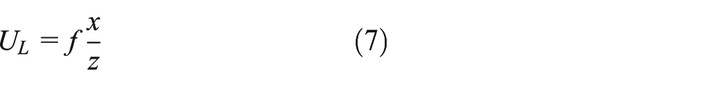

The tuple (UL UR) is known as a correspondence, and the related projections UL and UR are known as conjugate or homologous points. The distance between conjugate points is referred to as disparity (d), which is calculated using the following equation

Given a pair of conjugate points, the real-world distance of the original point from the stereo vision system can be calculated as follows

A stereo vision system requires camera model calibration for each camera. First, we have to set up a board of calibration with grid plane as shown in Figure 11 and obtain images from different rotations, angles, or positions by two cameras as in Figure 12.

Set/adjust positions of left/right cameras.

The board of calibration grid plane.
The calibration process uses the vision development module of NI software for acquiring internal parameters (distortion model coefficients, focal length, and optical center) and external parameters (rotation and translation matrices between corresponding camera-coordinate systems). The relative formulas are given as follows

After calibration, the image of object can be caught by both cameras of left and right, and the images need to be considered with the image correspondence7,17 in depth by three stages: pre-filtering, matching point, and post-filtering. After these stages, the processed images are shown in Figure 13. The flowchart of 3D image process is shown in Figure 14.
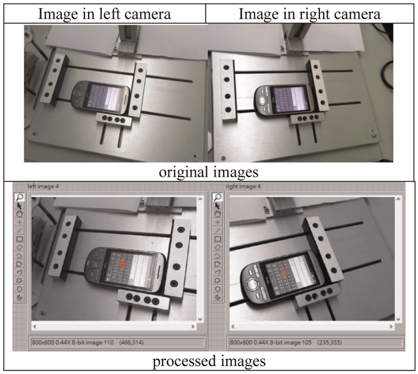
Image correspondence in depth.

Flowchart of 3D image process.
After completing calibration and image correspondence of object, the 3D coordinates can be obtained by the Q matrix as follows

Q is given as
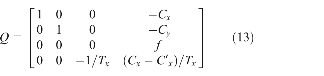
Tx is the X-component of the translation parameter.
Fuzzy control
Inverse kinematics is used to transform Cartesian coordinate information to joint coordinates. The required rotating angle of each robotic joint can be calculated after the end of point from 3D stereo coordinates from equations (14) and (15). Applying the link parameters, the pose of end-effector can be obtained, where


Fuzzy theory is then used in position control for five servo motors. It does not require complex mathematical model of the robot. The fuzzy rules are defined based on the touch panel of the smartphone as shown in Figure 15, which is the image captured from the object (touch panel of a smartphone).

Touch panel of the tested smartphone.
From the 3D stereo coordinate, we already obtained the center point (g) of object, and we have also used the transformation between pixel and unit (cm) to calculate the size of each column. Based on this concept, we can set the fuzzy rules by three definitions as follows: (1) the magnification area of X step: −4 to 4/−4 to 5/−2 to 4, (2) the magnification area of Y step: −1 to 1, and (3) the position of words: 0–9/0–10/0–7. According to these, we can set the fuzzy rules as follows:
Rule 1 (q): If magnification in the x-axis is negative longest and the magnification in the y-axis is positive, then the position of robotic arm is top of far left.
Rule 2 (w): If magnification in the x-axis is negative longer and the magnification in the y-axis is positive, then the position of robotic arm is top of medium far left.
Rule 3 (e): If magnification in the x-axis is negative long and the magnification in the y-axis is positive, then the position of robotic arm is top of short far left.
Rule 4 (r): If magnification in the x-axis is negative small long and the magnification in the y-axis is positive, then the position of robotic arm is top of small short far left.
Rule 5 (t): If magnification in the x-axis is medium and the magnification in the y-axis is positive, then the position of robotic arm is top of medium.
Rule 6 (y): If magnification in the x-axis is positive medium and the magnification in the y-axis is positive, then the position of robotic arm is top of medium right.
Rule 7 (u): If magnification in the x-axis is positive small long and the magnification in the y-axis is positive, then the position of robotic arm is top of small short far right.
Rule 8 (i): If magnification in the x-axis is positive long and the magnification in the y-axis is positive, then the position of robotic arm is top of short far right.
Rule 9 (o): If magnification in the x-axis is positive longer and the magnification in the y-axis is positive, then the position of robotic arm is top of medium far right.
Rule 10 (p): If magnification in the x-axis is positive longest and the magnification in the y-axis is positive, then the position of robotic arm is top of far right.
The rules for position at middle level and lower level are also similar, and the relative membership functions can be expressed as in Figures 16–18.

Membership functions of the X-axis of keypad.

Membership functions of the Y-axis of keypad.
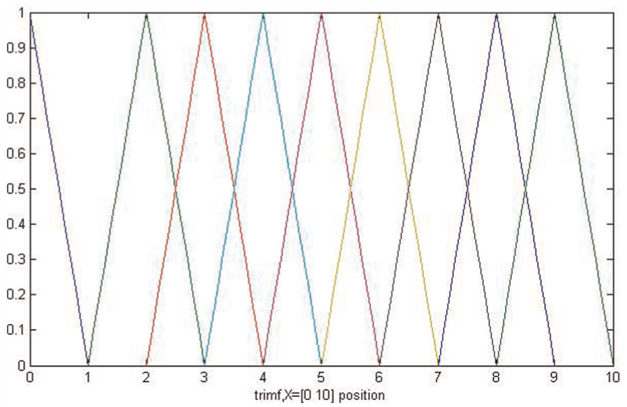
Membership functions of the position of keypad.
After completing this process, we can obtain all positions of keypad on the object (smartphone). We do not need to capture full range of keypad on object by 3D computation because too many feature points are hard to recognize and set right value for each letter and number. Figure 19 shows that if a specified point “g” is selected and measured by 3D computation, then all other points can be obtained by the proposed fuzzy control.

Feature points in different areas: (a) feature point only in one area and (b) feature points all over the keypad.
Experimental results
The overall steps of stereo calibration, 3D plane computation, and fuzzy control are shown in Figure 20. The first experiment presents the robotic arm pressing digit numbers. Initial setup of the system is shown in Figure 21. First, the command comes from the screen of the control panel of the smartphone test system. The webcam is set at the mid-position in front of the screen. The command is cached by the camera and is recognized by the OCR in the main processor (notebook). Digits “1234” are recognized as shown in Figure 22.

Flowchart of the overall steps of stereo calibration, 3D plane computation, and fuzzy control.

Initial position of the robotic arm from (a) top view and (b) side view.

Recognize the command from the control panel: (a) catch the image of the command from the control panel of the smartphone test system and (b) the command “dial a number 1234” is recognized by the OCR.
In the meantime, the 3D coordinates of central point of object will be computed and translated for robot precision adjustment. Figure 23 shows the sequence of the robot pressing desired number 1234. After the whole procedure is completed, the system will wait for a new command from the screen of the test system.

Press number 1234: (a) move the robotic arm to press digit “1” on object, (b) raise the robotic arm and ready for next digit, (c) move the robotic arm to press digit “2” on object, (d) raise the robotic arm and ready for the next digit, (e) move the robotic arm to press digit “3” on object, (f) raise the robotic arm and ready for the next digit, (g) move the robotic arm to press digit “4” on object, and (h) raise the robotic arm and ready for the next command.
Table 1 shows the performance of robot on pressing the object keypad by fuzzy rule after receiving command from OCR. We have checked by the different numbers, such as “1234,”“5678,”“9123,” or only set single command for some specified digit to check whether the robot can correctly press the keypad or not. From Table 1, only digit 3 has a slight difference as from the point of robotic arm, it is the farthest place with respect to robotic arm; the failed touching is caused by the situation of contact bounce (double touching). Table 2 shows the precision of stylus on the end of robotic arm with the center point on each button of keypad. The value is negative if stylus is pressed on the left side of the center point of each button, the value is positive if stylus is pressed on the right side. The button width of the center point is 6 mm.
Success rate of each digit (testing times: 10).

Average error of each digit (testing times: 10).

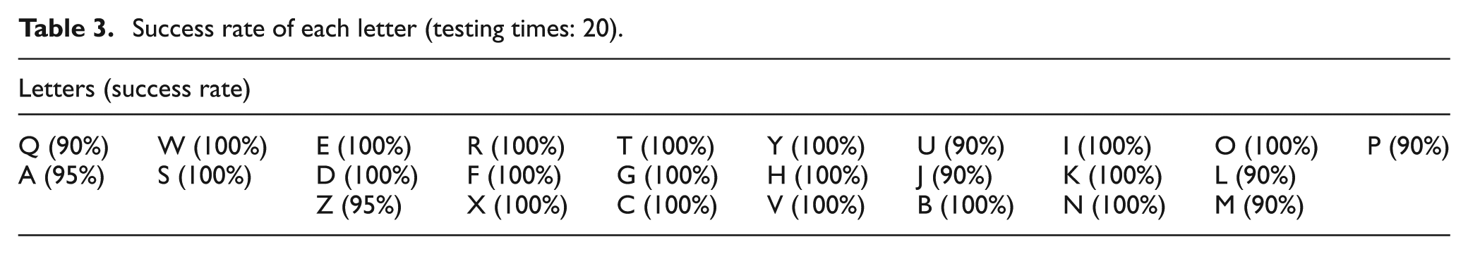
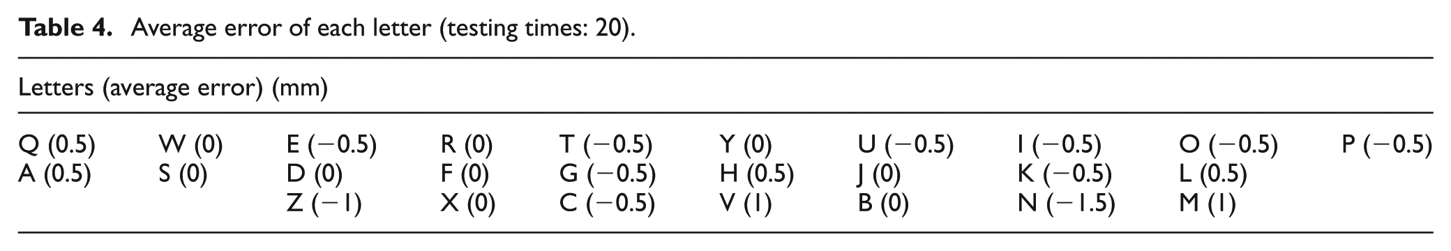
Second experiment presents the robotic arm pressing word “ZXCVBNM” on touch panel of the object (smartphone), as shown in Figure 24. Table 3 shows the performance of robot on pressing the object keypad by fuzzy rule after receiving command from OCR. We have tried different words, such as “QWERTYG,”“IOPGHJK,”“ASDFGHJ,”“QASDFGH,”“JKLZXCV,”“ZXCVBNM,” and “AZXCVBM,” to check whether the robotic arm correctly presses the keypad or not. From Table 3, we can find that less successful rates occurred at the edge of the tested smartphone keypad due to the configuration and characteristic of robotic arm. Table 4 shows the precision of stylus on the end of robotic arm with the center point on each button of keypad. The value is negative if stylus is pressed on the left side of the center point of each button, and the value is positive if stylus is pressed on the right side. The button width of the center point is 2 mm.

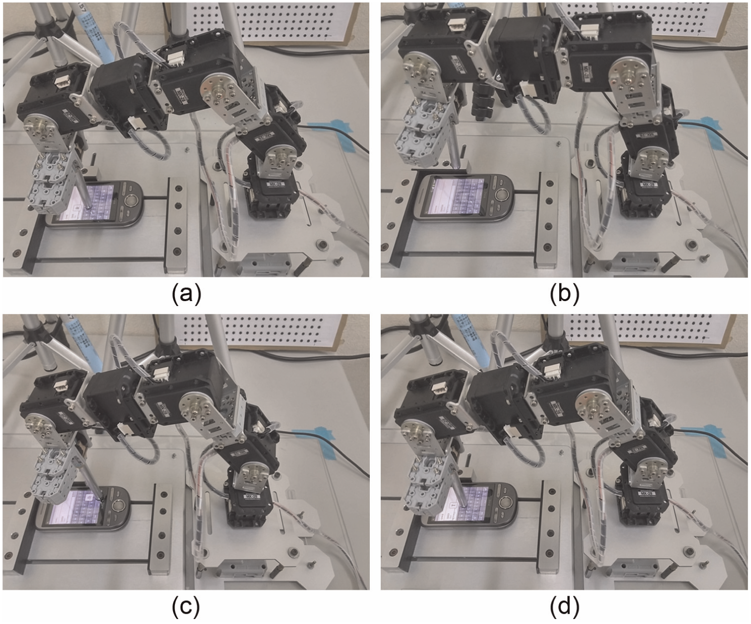
Press letters: (a) move the robotic arm to press letter “Z” on object, (b) raise the robotic arm and confirm the letter by OCR and ready for the next letter, (c) move the robotic arm to press letter “X” on object, (d) raise the robotic arm and confirm the letter by OCR and ready for the next letter, (e) move the robotic arm to press letter “M” on object, and (f) raise the robotic arm and confirm the letter by OCR and ready for the next command.
Success rate of each letter (testing times: 20).
Average error of each letter (testing times: 20).
There are two situations of unsuccessful touching which are nontouching and touching wrong letter on the object (smartphone). In the case of nontouching, the robotic arm will continue to press the same area with adjustment until the desired digit or button is pressed and recognized by OCR and then the process moves on for the next digit. In the case of unsuccessful touching, the robotic arm tries to press letter “T.” We have set a correct function when pressing on the left side of the desired letter, the robotic arm will adjust to negative 0.5 precision units until it presses desired letter correctly. In the same setting, when pressing on the right side of the desired letter, the robotic arm will adjust to positive 0.5 precision units, as shown in Figure 25.
The judgment recognition for unsuccessful touching: (a) move the robotic arm to press letter “T,” wrong touching; (b) raise the robotic arm and wait for vision recognition; (c) delete the incorrect letter; and (d) press letter “T” with correction value, now it is right touching.
On this control system and based on the same 3D calibration data, the robot can quickly get center point of different smartphones and translate to robot precision value. The robotic arm can be moved to press digit and letter on the keypad of different smartphones as shown in Figure 26.

Press desired digit on the keypad of different smartphones.
Conclusion
In this study, an intelligent control scheme based on image processing, pattern matching, and fuzzy control is proposed to smartphone automatic test system. The 3D computation, inverse kinematics, and transformation between pixel and centimeter are applied to obtain the desired locations of digits or letters from keypad of an object (smartphone), which is a new design to other articles. The proposed system can control a robotic arm with better precision and accuracy to touch the desired buttons of a tested smartphone. The 3D stereo vision theory is used to obtain the real distance between object and robotic arm. By the NIVA, the OCR with HSL image process theory is applied for receiving command, and it can identify the words from the monitor of control panel properly in real time. We have also developed a new procedure for image process by the use of reverse process, equalizer process, and auto threshold for numbers and words to overcome poor contrast or bad lightness. The feedback of each motor is added to monitor and limit the motion out of control, and the movement of robotic arm can be improved with good precision and accuracy in touching smaller object. In the case of missing touching, a simple adjustment process is proposed in this study that can automatically trim the end-effector of the robotic arm to the desired region. With fuzzy theory, the robotic arm can be controlled flexibly. Experimental results show that the robotic arm can execute desired commands and perform automatic smartphone test successfully.
Footnotes
Academic Editor: Stephen D Prior
Declaration of conflicting interests
The author(s) declared no potential conflicts of interest with respect to the research, authorship, and/or publication of this article.
Funding
The author(s) received no financial support for the research, authorship, and/or publication of this article.