
Abstract
A multibody dynamic model of the self-energizing synchronizer in a 14-speed manual transmission gearbox is presented. While the contact forces between the engaged splines/teeth and friction torques between the synchro rings are hardly observed by conventional experiments, detailed contact and friction models in consideration of lubrication are established to simulate these contact/friction forces during shifting. The space motion of the sleeve is considered; thus, the differences in the contact forces between the engaged teeth can be simulated and observed. A pneumatic model is established to model the varying shift force acting on the synchronizer. An experiment is conducted for the self-energizing synchronizer to validate the presented synchronizer model. Moreover, to demonstrate the self-energizing function of the synchronizer, a synchronizer without self-energizing mechanism is modelled and compared with the original one.
Introduction
Synchronizers are widely equipped in vehicle transmission gearboxes, including manual transmission (MT), automated manual transmission (AMT) and dual clutch transmission (DCT). The main function of synchronizer is to decrease abnormal impact during shifting and to achieve the correct operation of transmission as well as the drivers’ shifting comfort in MT.
While in AMT and DCT synchronizers are usually simplified as friction elements, as will be further discussed, previous works on the synchronization and engagement process are mainly focused on MT.1–8 Liu and Tseng 1 developed a simulation model of the double-cone synchronizer. Displacement of the sleeve, relative velocity, cone torque, index torque and relative angle were obtained from the analytical model. Lovas et al. 2 defined and studied the eight main operating phases of the Borg–Warner-type synchronizer with one conical surface clutch. The stick–slip and second bump were investigated in detail. Hoshino 3 proposed an analytical model using ADAMS to clarify why and how abnormal shift force occurs while upshifting. Kim et al. 4 developed a shift force simulator for MT to estimate the shift force to the driver’s hand. The simulator could calculate the sleeve displacement, cone torque, index torque, sleeve force, shift force and the speed of the input and output shafts. Li and colleagues5–7 systematically studied three types of MT synchronizers including single-cone synchronizer, double-cone synchronizer and self-energizing synchronizer using multibody dynamic simulation technique or finite element analysis method.
When the aim of the multibody model is to predict the friction between the synchro rings, the effect of lubrication should be considered. In multibody dynamics,8–10 friction and lubrication phenomena are widely observed and researched, such as imperfect joints11–14 and bearings. 15 Detailed studies about synchronizer friction in consideration of lubrication are presented in Abdel et al. 16 and Paffoni et al. 17 Abdel et al. 16 derived the theoretical performance equations for the triple-cone synchronizers. Paffoni et al. 17 divided the period of synchronization into three stages of operation: viscous, mixed and dry. Paffoni’s lubrication theory is adopted in this study.
In actual operation condition, synchronizer is a component with high failure rate in gearbox due to abnormal friction and abnormal contact. Socin and Walters 18 also pointed out that clash occurred when the synchronizer was not energized or only partially energized. However, in the above studies about MT synchronizers,1–7 the contact and friction phenomena between the synchronizer components were not deeply discussed and the contact forces were seldom shown, such as the contact forces on the engaged teeth. In this article, the major frictions and contacts between the synchronizer components are carefully modelled and analysed.
AMTs are generally constituted by a clutch, a gearbox and electro-mechanical or electro-hydraulic actuators. Modelling and analysis of synchronizer dynamics for AMT can be found in a number of studies,19–25 but the core is the development of control strategy. Synchronizer is generally modelled as a simple friction element represented by a friction torque. The main function of the synchronizer is thought to change the power path through the transmission. Tseng and Yu 19 proposed a practical gearshifting control strategy with respect to AMT for an electric vehicle. Simple equations were used to represent the synchronization process. Zhong et al. 20 proposed a 3-degree-of-freedom (DOF) finite element model of the AMT where the synchronizer torque was modelled as a function of the shifting force, the average effective radius, the friction coefficient and the cone angle of the ring. Galvagno et al. 21 presented the kinematic and dynamic analyses of a power-shift AMT. Synchronization stage was represented by a friction torque. Lin et al. 22 proposed a novel gearshift system that utilized a 2-DOF electromagnetic actuator to realize the automation of gearshift, in which synchronizer was modelled as a simple friction element. Lucente et al. 23 developed physically based detailed nonlinear models of the electro-hydraulic actuated gearbox and the dry clutch electro-hydraulic actuator of an AMT. The synchronizer was modelled as a device which applied Coulomb friction torque to the cogwheels. Amisano et al.24,25 presented kinematic and dynamic analyses of the AMT in consideration of a torque gap filler, but synchronizers were modelled as simple switches, which could change the power path through the transmission.
DCT combines technologies of automatic transmissions and MT. Extensive research into the shift control dynamics of DCTs has been performed by Walker and colleagues.26–33 In Walker’s works, lumped parameter methods were frequently used to model the transmission. Synchronization process was usually divided into several stages, but each stage was represented by simple equations. The cone torque and index torque represented the different steps of synchronizer engagement.
More researches on synchronizer dynamic modelling for DCT were investigated in the literatures,30–35 where the synchronizers were so simplified that the function of synchronization was not emphasized. In the works of Li et al. 34 and Lu et al., 35 the synchronization process was divided into several phases and each phase was presented by several ordinary differential equations. Kulkarni et al. 36 and Galvagno et al. 37 modelled the synchronizer as a friction element in DCT vehicle. Synchronizer was modelled by simple state equation of the sleeve position in the DCT model of Min et al. 38 Ahlawat et al. 39 developed a reduced dynamic lumped parameter model for DCT in which synchronizers were presented as power flow switches. Wu et al. 40 proposed a nonlinear dynamic model of passenger car driveline with DCT, but the synchronization process of the synchronizer was almost neglected.
The main purpose of this work is the modelling and simulation of synchronization and engagement process for the MT self-energizing synchronizer during shifting process. The contact forces on the engaged teeth are carefully modelled and simulated, to the authors’ knowledge, which are seldom shown in other associated literatures.
This article is organized as follows. The structure and synchronization process for self-energizing synchronizer are presented in section ‘Synchronizer mechanism and synchronization process’. The experiment for synchronization and engagement is introduced in section ‘Experiment’. Section ‘Modelling of self-energizing synchronizer’ discusses details of modelling of synchronizer system dynamics. In section ‘Simulation and analysis’, the simulation results are shown and analysed, and part of the simulation results are compared with the corresponding experimental data. Finally, section ‘Conclusion’ summarizes the main conclusions throughout the article.
Synchronizer mechanism and synchronization process
Synchronizer mechanism and multibody model
The research object is the self-energizing S3 in 14-speed MT as represented in Figure 1. Only the dynamics of the synchronizer is focused and the dynamics of the whole transmission system is out the scope of this article. Symbols G1–G14 represent the gears and S1–S5 represent the synchronizers. S1, S4 and S5 are single-cone synchronizers, and S2 and S3 are self-energizing synchronizers. It is noted that the reverse shaft is not presented in the figure. The basic properties of the gear train for 1st to 14th gear are shown in Table 1. Take first gear for example, S1-G2, S5-G7 and S4-G6 mean synchronizers S1, S5 and S4 are engaged with gears G2, G7 and G6, respectively.
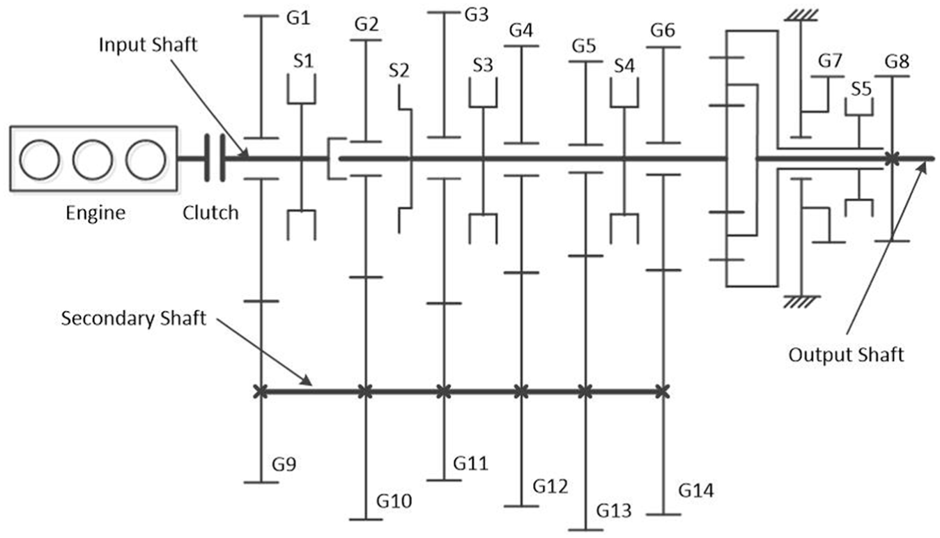
Structure of 14-speed MT (G1–G14: gears; S1–S5: synchronizers).
Gear properties.
The multibody model of the self-energizing synchronizer is established in ADAMS/View software, as shown in Figure 2. A typical self-energizing synchronizer mechanism layout includes the major components: shift fork, sleeve, hub, claw plate, outer ring, intermediate ring, inner ring and clutch gear. The physical parameters of the major components are listed in Table 2.

Typical assembly of a self-energizing synchronizer.
Physical parameters of the synchronizer.

As the synchronizer structure is symmetric, one side of the synchronizer is considered. Because the reflected inertia from the vehicle is much larger than that of the transmission gearbox, the hub is assumed to be fixed on the ground. The rotational velocity of the clutch gear equals to the relative rotational velocity between the transmission gear and the synchronizer. In addition, the outer ring, intermediate ring and the inner ring can rotate and move along the X-axis. The clutch gear can just rotate along the X-axis. The claw plate and the sleeve can move axially along the X-axis.
In the following sections, the synchronization process from 11th gear ratio to the 9th gear ratio is simulated and analysed, because high failure rate is found in this downshift process caused by abnormal frictions and contacts. The simulation of this analytic model is set to end time at 0.6 s with the calculation interval of 0.001 s. The simulation conditions used for simulating the shift from 11th gear ratio to the 9th gear ratio are listed in Table 3.
Simulation conditions.

It should be noted that a drag torque should be applied at the clutch gear in the multibody model. The drag torque results from churning oil and is modelled as a constant in this article. During the upshift, the drag torque decreases the relative rotational velocity of the transmission gear and the synchronizer; but increases the relative rotational velocity during the downshift. Details of modelling of contacts/frictions and shift force are illustrated in section ‘Modelling of self-energizing synchronizer’.
Synchronization process
The operation of the synchronizer from neutral position to full engagement is divided into eight stages related to sleeve displacement, as shown in Figure 3:
First free flight (movement of the sleeve);
Pre-synchronization (the sleeve slides over the plunger);
Boost force built up (boost force is generated and applied at the sleeve);
Synchronization (mesh of the sleeve and outer ring; the positions of sleeve and outer ring maintained);
Disengaged (the sleeve turns the outer ring and moves on);
Second free flight (movement of the sleeve);
Double bump (impacts between the sleeve and the clutch gear);
Engagement (mesh of the sleeve and the clutch gear).

Presentation of the relative position of synchronizer components during the entire synchronization process: (a) sleeve in neutral position, (b) pre-synchronization, (c) boost force built up, (d) synchronization, (e) disengaged, (f) free flight, (g) second bump and (h) engagement.
First free flight
Free flight means that the sleeve moves forward axially without significant mechanical resistance. During this phase, an axial force is applied to the sleeve to initiate the shift. The sleeve moves from the neutral position axially until the plunger is pushed by the sleeve to get in touch with the outer ring.
Pre-synchronization
The sleeve moves forward slightly and the sleeve is locked by the plunger as shown in Figure 4. The sleeve stops moving axially. The lubrication oil between the conical surfaces (surfaces between outer ring, intermediate ring and inner ring) starts to be squeezed out.

Positions of the synchronizer components during pre-synchronization stage.
Boost force built up
The claw plate rotates and pushes the boost teeth on the sleeve. The sleeve also pushes the claw plate backward and the claw plate compresses a disc spring. Thus, a boost force produced by the disc spring is applied at the sleeve. Then the sleeve will slide over the plunger under the boost force and shift force. The boost principal of the self-energizing synchronizer is discussed in Appendix 1.
Synchronization
The spline position of each component during angular velocity synchronization is shown in Figure 3(d). After most of the lubrication oil has been evacuated, full lubrication is replaced by mixed lubrication. The axial force applied at the sleeve increases and maintains practically at a constant. The mixed frictions between the conical surfaces consume the kinetic mechanical energy difference, and the angular velocity difference between the synchronizer and the transmission gear (clutch gear) decreases towards 0. The intermediate ring is heated by the dissipated friction energy and its diameter increases.
Disengaged
When the relative angular velocity between the synchronizer and the clutch gear becomes 0, the friction phenomena between the conical surfaces disappear. The intermediate ring previously heated by the dissipated friction energy loses the heat so that its diameter decreases. The resistant forces on the spline chambers of sleeve and outer ring disappear, and the sleeve starts to move axially. The movement of the sleeve turns the outer ring while their chambers remain in contact. Finally, the sleeve passes through the spline of the outer ring. The axial velocity of the sleeve increases from 0 to a maximum value while the axial force decreases to a minimum value.
Second free flight
The sleeve moves forward axially after it separates with the chambers of the outer ring, but the sleeve still meshes with the outer ring. The angular velocity of the outer ring is assumed to be equal to that of the sleeve. The velocity of the sleeve maintains a maximum and the axial force maintains a minimum.
Double bump
When the sleeve approaches the spline chambers of the clutch gear, a small increase in the axial force is required as the chamber surfaces experience impact. This axial force increases gradually until the tangential force component from the force equilibrium on the chambers is large enough to turn the outer ring previously stuck on the cone. The increase in the axial force is the first component of the so-called double bump phenomenon.
After separation of the outer ring and the sleeve, the sleeve begins to turn the clutch gear when it moves forward at low axial velocity. As the axial force required for turning depends on the relative position of the sleeve splines and the gear splines, a narrower turning angle requires more force to turn the gear in a shorter time. The increase in the axial force is the second and major component of the double bump phenomenon.
Engagement
After turning the clutch gear, the sleeve continues moving forward axially and meshes the spline of the clutch gear to complete the engagement. The entire synchronization process is finished.
Experiment
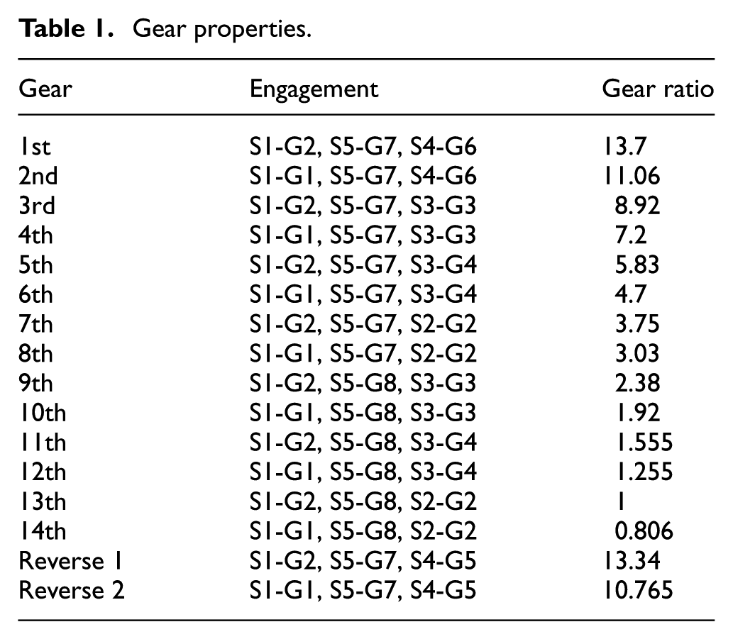
Figure 5 represents the test set-up for the self-energizing synchronizer. The set-up is driven by the motor and an initial speed is achieved. Then the required axial force is brought up by pneumatic cylinder and transmitted to sleeve via shift fork. The sleeve travels axially and the synchronization and engagement process begins until the sleeve stops moving.
Test set-up for synchronizer.
The measured signals of each single shift are recorded by a data acquisition board located in a computer. The displacement of the cylinder is obtained by the position sensor and then the displacement of the sleeve can be obtained through simple calculation. The force sensor is used to measure the axial shift force acting on the shift fork. The angular rate sensor measures the relative rotation velocity of the synchronizer and the clutch gear. The test results are shown and compared with simulation results in section ‘Comparison of simulations and experimental data’.
Modelling of self-energizing synchronizer
Basic multibody model of the synchronizer is established in section ‘Synchronizer mechanism and multibody model’. This section introduces some important details of contact/friction and shift force.
Modelling of contact forces between engaged teeth
Geometrical definition
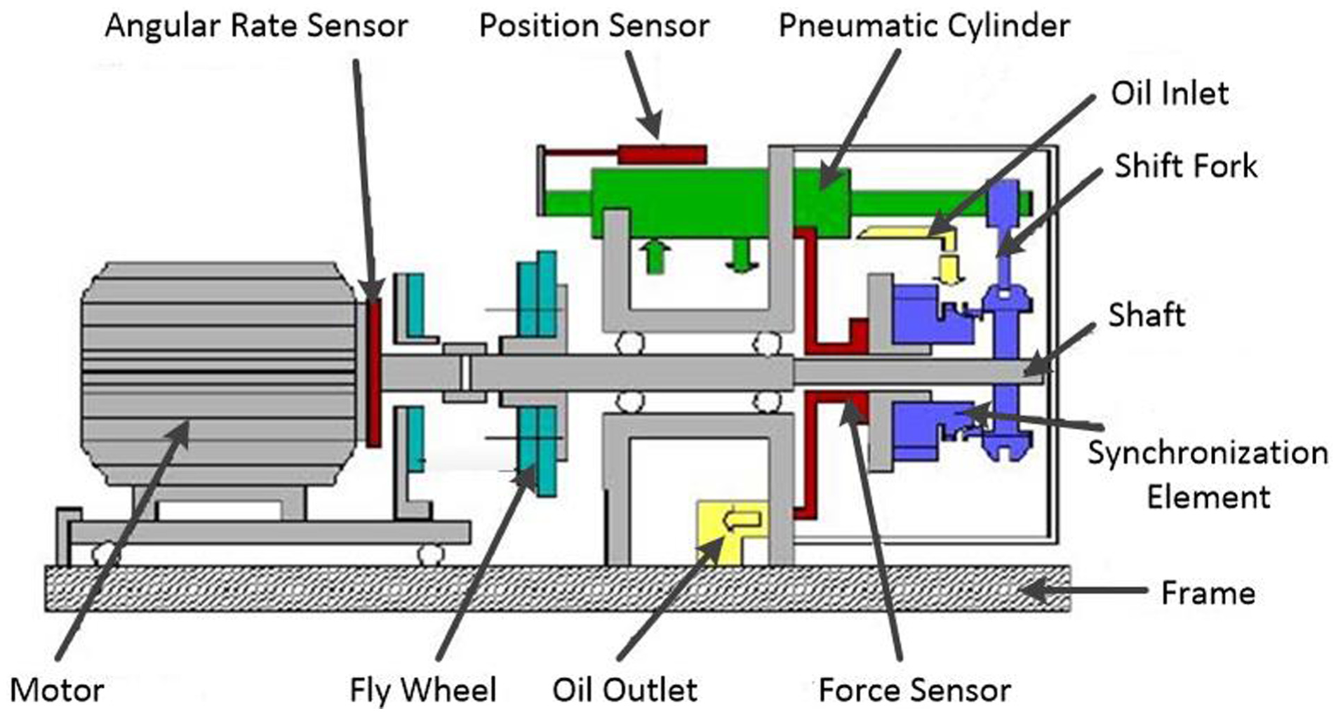
The engaged teeth of the synchronizer components are illustrated in Figure 6. Exactly following contact forces are carefully investigated:
Contacts between claw plate teeth and boost teeth (shown in Figure 3(c));
Contacts between boost teeth and outer ring teeth (shown in Figure 3(d));
Contacts between sleeve teeth and clutch gear teeth (shown in Figure 3(g)).
Teeth of synchronizer components.
Note that both the boost teeth and sleeve teeth belong to the sleeve. The claw plate has four teeth; the sleeve has 8 boost teeth and 48 sleeve teeth; the outer ring has four teeth; the clutch gear has 60 teeth. For each claw plate tooth, two contact forces are defined between the claw plate tooth and two sleeve boost teeth. For each outer ring tooth, two contact forces are defined between the claw plate tooth and two sleeve boost teeth. Totally, eight contacts are defined between the claw plate teeth and sleeve boost teeth and eight contacts are defined between the sleeve boost teeth and outer ring teeth. For each claw plate tooth or outer ring tooth, it can only contact with only one sleeve boost tooth. For this reason, four contact forces between the claw plate and sleeve can be observed in Figure 15 and four contact forces between the sleeve and outer ring in Figure 16. For simplicity, all the clutch gear teeth are considered as one part so that 48 contacts are defined between the sleeve teeth and the clutch gear, which can be observed in Figure 17.
Contact point detection
The contact surfaces between the teeth are all planes; thus, the contact point detection is easily implemented. Consider two generic surfaces i and j, as shown in Figure 7, defined by the parametric functions


Generic surfaces for contact detection.
A two-step methodology is used here to determine the locations of the contact points.41,42 First, the following four geometric equations are defined and solved to find the surface parameters that define the coordinates of the candidates to be contact points between the surfaces

The tangent vectors

The unit normal vectors
The second step of the method is to evaluate the penetration condition to check whether the points are in contact or not. The penetration condition is

This system of equation (5) is solved for every pair of points which may come into contact. If a pair of points is in contact, then equation (5) is satisfied and vector
Normal contact force
For the judgement of a contact, the Kelvin–Voigt dissipative contact model 43 is adopted that combines a linear spring with a linear damper. These two elements are associated in parallel, and the contact force model can be formulated as

where
Tangential friction force
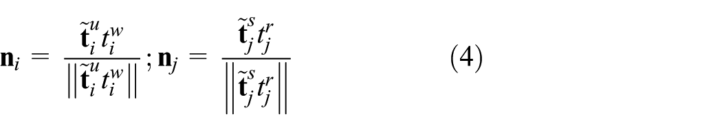
A modified Coulomb friction model is adopted in this study to compute the tangential friction force resulting from the normal contact and relative tangential velocity of two contact teeth. The friction coefficient is defined as a function of the relative tangential velocity
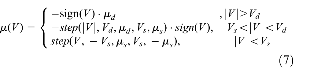
where
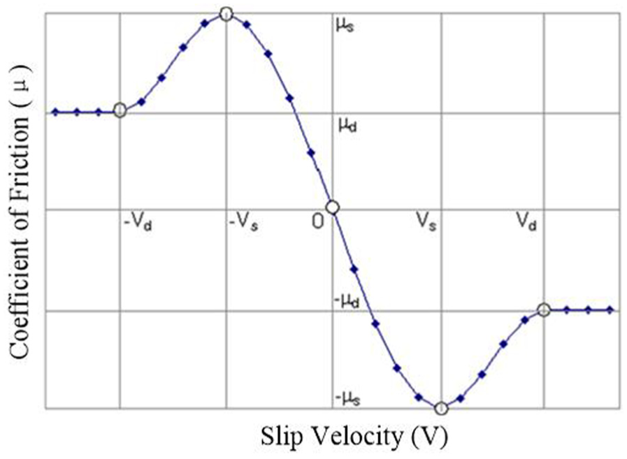
Friction coefficient varies with slip velocity.
Modelling of friction torques between synchro rings
Figure 9 shows the assembly of the synchro rings. In this section, the friction torque between the outer ring and the intermediate ring and the friction torque between the intermediate ring and the inner ring are modelled. For simplicity, it is assumed that the friction torque between the outer ring and the intermediate ring equals to that between the inner ring and the intermediate ring, but they are in the opposite direction. Thus, the sum of torques applied at the intermediate ring is zero. The contact forces

where x indicates the axial distance between the outer ring (inner ring) and the intermediate ring, and v indicates the axial relative velocity between the outer ring (inner ring) and the intermediate ring.

Assembly of the synchro rings.
The friction coefficient in the cone surfaces varies with the thickness of the lubricant between the cones of the synchro rings. As a result, the friction in the cone surfaces can be divided into three stages: viscous, mixed and dry. At the beginning of the mixed stage, the friction coefficient starts with a small value
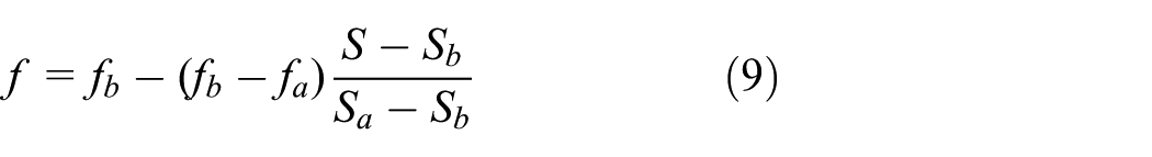
It can be seen the variation in the friction coefficient depends on the initial and final values of the variable S, that is,

The sliding velocity is expressed by

where

where b is the width of the contact rings and

The above formulas (8)–(13) are applied for the friction torque between the outer ring and the intermediate ring and friction torque between the intermediate ring and the inner ring.
Modelling of shift force
As mentioned in the synchronizer experiment, the sleeve is driven by a pneumatic cylinder. Figure 10 shows the modelling of the shift force. The multibody module receives the pneumatic force

Pneumatic module for shift force and multibody module.
The ideal gas inside chamber i (

where
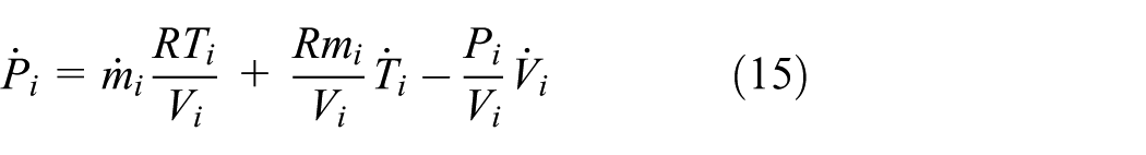
where


where
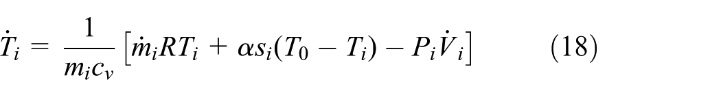
where
The rate of mass flow
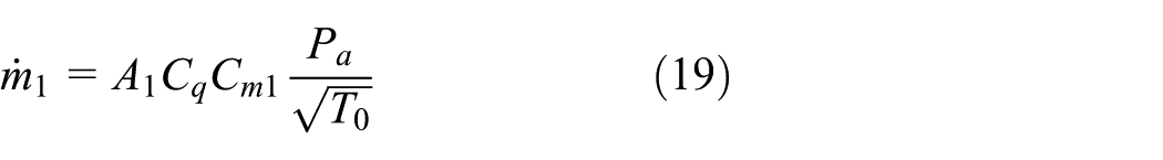

where
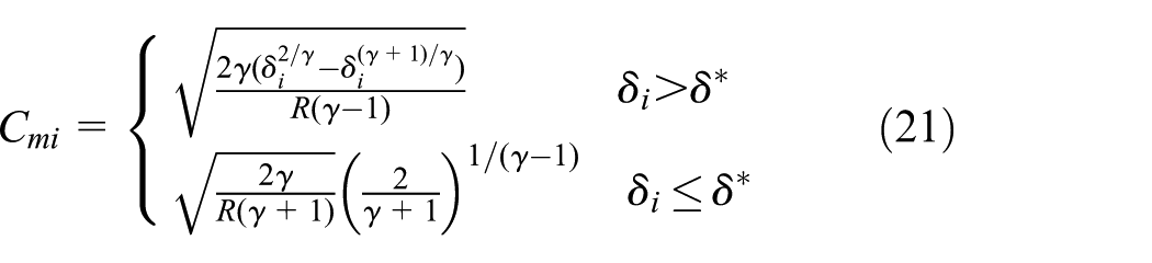
In equation (21),

From equations (14) to (22), the pressure

Different from synchronizer models in other literatures1–4 where the sleeve can only move axially, the space motion of the sleeve in this article is considered by introducing the flexible shift fork and by applying the shift force on it, which is illustrated in Figure 10. Since the shift fork and the sleeve are connected by fixed joints, the sleeve can rotate slightly along the Y-axis and Z-axis besides its axial movement along X-axis. Due to the slight rotation movement of the sleeve, the sleeve teeth generally have different contact forces during synchronization process. For instance, the boost forces on the sleeve often have small differences as a result of space motion of the sleeve, as will be shown in Figures 15–17 in section ‘Simulation and analysis’.
Simulation and analysis
Comparison of simulations and experimental data
The synchronization process from 11th gear ratio to the 9th gear ratio is simulated for the self-energizing synchronizer. In this section, the results of the comparison between the numerical simulations and experimental data are shown in Figures 11–13, including displacement of the sleeve, shift force acting on the sleeve and the relative rotation speed between the synchronizer and the clutch gear.

Sleeve axial displacement.

Shift force acting on the shift fork.
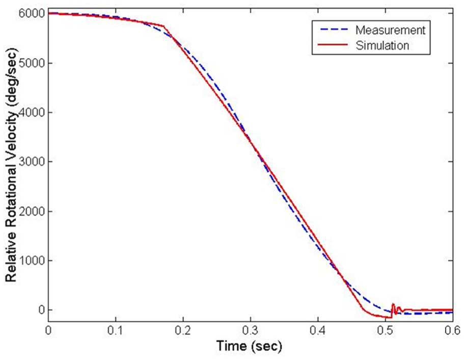
Relative rotational velocity between the transmission gear and synchronizer.
Figure 11 shows the displacement of the sleeve during the entire shifting process. As mentioned above, the movement of the sleeve can be divided into several stages. First, the sleeve moves forward until it contacts with the plunger. At the same time, the cone torque is yielded from the friction force on the cone surface to start the synchronization. After synchronization, it passes through the outer ring and continues to move towards the clutch gear. The entire shifting process is finished when the sleeve passes through the clutch gear. The movement of the sleeve can be confirmed by matching the measurement data.
Figure 12 shows the shift force acting on the shift fork. The shift force can also be divided into several stages. During the first free flight, the shift force is small. When the sleeve gets in touch with the plunger, the shift force becomes larger to push the sleeve. After that, the shift force continues increasing during the synchronization stage. At the end of synchronization, the sleeve gets engaged with the outer ring spline and the shift force decreases quickly until it approaches a small constant. The shift force relates to the movement of the sleeve. When the sleeve is stopped by the plunger or outer ring, the shift force becomes larger. When the sleeve moves without significant resistance, the shift force becomes relatively small. This fact can be observed from both the experimental data and the simulation results. Moreover, the simulation results have a good agreement with the experimental data.
Figure 13 shows the relative rotational velocity between the clutch gear and the synchronizer. In the simulation model, as the hub is fixed on the ground, the rotation speed of the clutch gear equals to the relative speed between the clutch gear and the synchronizer. During the synchronization stage, the rotation speed of the clutch gear decreases quickly until it approaches 0. As the sleeve contacts and engages with the clutch gear, the clutch gear rotation speed varies from negative to positive at the final stage, which can be observed from simulation but can hardly be observed from measurement.
Dynamic simulations
In this section, the dynamic simulation results that can hardly be obtained by measurement are presented, including the cone torque and the index torque, the boost force produced by disc spring, the contact forces between the sleeve and the outer ring and the contact forces between the sleeve and the clutch gear, illustrated through Figures 14–17.

Index torque and cone torque.

Contact forces between claw plate teeth and boost teeth.
Contact forces between boost teeth and outer ring teeth.

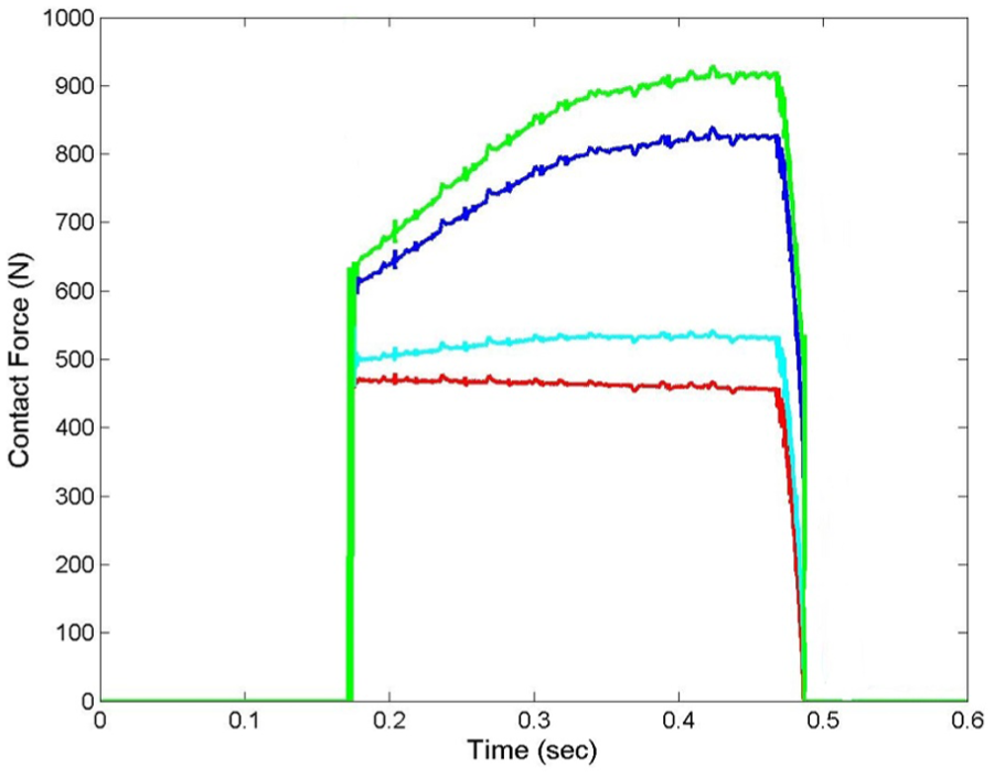
Contact forces between sleeve teeth and clutch gear teeth.
Figure 14 shows the index torque and the cone torque during the entire shifting process. During the pre-synchronization stage, the cone torque is small because the contact forces between the rings are small. At the beginning of synchronization, the sleeve pushes the outer ring; the gap between the outer ring and the inner ring decreases and the lubricant is drained out, which leads to an increase in the contact force and friction coefficient between the cone surfaces. Thus, the cone torque increases quickly at the beginning. The index torque shows up later than the cone torque, and it is always smaller than the cone torque before the sleeve and the outer ring engage with each other. At the end of synchronization stage, the cone torque began to be lower than the index torque. Then the sleeve moves forward and engages with the outer ring. As soon as the sleeve and the outer ring are engaged, both the cone torque and index torque decrease rapidly to 0.
Figure 15 shows the boost forces between the claw plate and the sleeve, that is, the contact forces between the claw plate teeth and the boost teeth. As the claw plate has four teeth, there are four boost forces. Note that there are small differences between these four boost forces as a result of the space movement of the sleeve. The boost forces only show up during the synchronization stage. The boost forces increase rapidly at the start of the stage and decrease rapidly at the end. The boost principal of the self-energizing synchronizer is discussed in Appendix 1.
Figure 16 shows the contact forces between the sleeve boost teeth and the outer ring teeth. The outer ring has four teeth, so there are four contact forces. These contact forces increase quickly at the start of the synchronization stage and decrease quickly at the end. The small differences between these four contact forces are caused by the space motion of the sleeve. During the ‘synchronization’ stage the contact forces on the blocking teeth approximately equal to the sum of the shift force on the shift fork and the boost forces produced by the claw plate.
Figure 17 shows the contact forces between the sleeve teeth and the clutch gear teeth. The sleeve has 48 blocking teeth and all the teeth of the clutch gear are modelled by a single part, so there are 48 contact forces in the figure. The contacts and engagement between the sleeve and the clutch gear occur in an extremely short time. Generally, several contacts will happen in this short period. When the sleeve contacts with the clutch gear for the first time, the sleeve may move backward because of the small relative velocity between the sleeve and the clutch gear. Then the sleeve moves forward and contacts with the clutch gear again. This procedure may repeat several times until the sleeve crosses over the teeth of the clutch gear and then it slides along the chamber of the teeth. As the number of contacts increases, the amplitude of contact force becomes smaller and smaller, because the relative velocity of the sleeve and the clutch gear decreases. It should be noted that there are small differences between the 48 contact forces as a result of the space motion of the sleeve.
Analysis of synchronizer without self-energizing mechanism
Due to the function of self-energizing, the synchronizer in this article can accomplish shifting process with less shift force. It means that the driver needs less effort when shifting. In this section, to demonstrate the self-energizing function, simulation and analysis are carried out for the synchronizer without self-energizing mechanism, and the simulation results are compared with the original one. The simulation results are presented in Figures 18 and 19, including the sleeve displacement and the shift force. Moir 45 even proposed several objective measures for evaluating and assessing the gearshift quality, which allow comparisons of shift quality to be made between different synchronizers. Some objective measures will be used in this section.

Comparison of the sleeve displacements.

Comparison of the shift forces.
Figure 18 shows the comparison of the sleeve displacement. It can be found that the synchronization time of the synchronizer without self-energizing mechanism is much longer than that of the original one. The shift time for the synchronizer without self-energizing mechanism is about 0.8 s while it is about 0.6 s for the original one.
Figure 19 shows the comparison of the shift force. The ‘time synchronization integral’ is used to evaluate the shift effort. The time synchronization integral is defined as the integral of shift force with respect to the time during synchronization period, illustrated as the shadow areas in Figure 19. It can be seen that the time synchronization integral of the synchronizer without self-energizing mechanism is much larger than that of the original one. Moreover, the maximum shift force of the synchronizer without self-energizing mechanism is also much larger than that of the original one.
Table 4 summarizes the objective measures for these two synchronizers. Even when larger shift force is applied, both the synchronization period and shift time are still longer than the original one. It proves that the self-energizing mechanism can save much effort during shifting. With the self-energizing mechanism removed, shifting requires much more efforts.
Objective measures for evaluation of shifting quality.

Conclusion
A multibody dynamic model is developed to simulate the synchronization and engagement process for self-energizing synchronizer in a 14-speed MT. The shift force is modelled by a pneumatic module. The space motion of the sleeve is considered so that the differences in the contact forces of the engaged teeth can be modelled and observed. The contact forces between the meshed splines/teeth and friction torques between the synchro rings in consideration of lubrication are simulated, which are hard to be obtained with conventional experimental approach. To state the self-energizing function of this type of synchronizer, a synchronizer with self-energizing mechanism removed is simulated, analysed and compared.
An experiment is conducted for the self-energizing synchronizer. The shift force, sleeve axial displacement and relative rotation velocity of the clutch gear are obtained. The simulation results are in good agreement with the experimental data. Thus, the efficiency and accuracy of the synchronizer model can be guaranteed.
Nonetheless, the synchronizer model can be further improved in some aspects:
The intermediate ring is floating in the lubrication oil during synchronization; thus, it actually has complex space motion and thermos-hydraulics. In this article, the synchro rings are simply modelled as friction cones in consideration of lubrication.
In the synchronizer model, all the 60 teeth of the clutch gear are modelled by a single part because of computational problem. This simplicity is reasonable if the state of single clutch gear tooth is not concerned. To research the single tooth of the clutch gear, each tooth of the clutch gear should be modelled as a separate part.
There exists randomness of the engagement process between the sleeve and the clutch gear. Although the randomness is mentioned in Liu and Tseng 1 and Luo et al., 6 it is not deeply considered. Actually, some design variables in the synchronizer model should be modelled as random variables and some statistical simulation results can be obtained.
These problems are of great importance and interest and should be further researched in future work.
Footnotes
Appendix 1
Appendix 1 introduces the boost principal of the self-energizing synchronizer. After the pre-synchronization stage, the claw plate rotates and pushes the boost teeth forward. As shown in Figure 20, the force acting on the blocking teeth
Actually, the boost force is produced by the disc spring. When the claw plate pushes the boost teeth forward, the boost teeth also pushes the claw plate backward. When the claw plate moves backward, it compresses the disc spring. Then the disc spring produces a spring force
where
It should be noted that the boost force has a maximum because the claw plate has a maximal backward displacement
where
where
Academic Editor: Chuanzeng Zhang
Declaration of conflicting interests
The author(s) declared no potential conflicts of interest with respect to the research, authorship and/or publication of this article.
Funding
The author(s) disclosed receipt of the following financial support for the research, authorship and/or publication of this article: This research was supported by the National Natural Science Foundation of China (11472112; 11502083). This financial support is gratefully acknowledged.