
Abstract
A nonlinear dynamic model of a helicopter flying through a variable microburst wind field is developed. Equivalent wind field models are established based on the Soesman and gust models to analyze quantitatively the abrupt change when a helicopter enters and leaves the wind field. The comparison of the simulation results with and without the equivalent model shows that the equivalent model has good accuracy for flight dynamic simulation of a helicopter under atmospheric disturbance. Real-time simulation of helicopter forward flight through the microburst wind field is also conducted at different positions and heights to analyze the influence of wind at the side direction and the downward flow on helicopter flight performance. The results indicate that wind at the side direction enables the helicopter to carry out complicated lateral movements with different yaw characteristics. Furthermore, with the increase in flight height, the downward flow leads to faster rate of descent and stronger vertical overload, both of which will affect the flight safety of the helicopter.
Introduction
Microburst is a type of complicated low-altitude wind field that appears after local downward flow reaches the ground. 1 It is a common phenomenon of wind shear at low altitude. 2 When an airplane encounters a microburst, it will experience the contrary wind belt first and then go through the tail wind belt, which has a strong crosswind and downward flow. Therefore, microburst is a large threat to flight safety. 3 Given that the helicopters often fly at altitudes lower than 1000 m, and that the influence of a wind field’s aerodynamic force on helicopter rotors is highly complicated, 4 a study on the flight characteristics of the helicopters when encountering microburst is crucial.
Due to the particularity of the structure, complexity of pneumatic system, and seriousness of coupling of each channel of the helicopters, a nonlinear dynamic model has better accuracy for estimating the dynamic characteristic and flight quality of the helicopters compared with a linear model. 5 With the development of theory and calculation ability, more and more attention is paid to the helicopter nonlinear flight dynamics model.6–8 In recent years, an increasing number of researches on the wind field response of the nonlinear system of the helicopters have been conducted.4,9,10 Another key technology on helicopter flight through microburst is the establishment of a wind field model. In-depth studies on establishing a microburst model have been carried out, and some engineering models have been established, namely, function fitting models and hydromechanics models. The former mainly includes the Soesman 11 and Bowles–Oseguera 12 models, and the latter mainly includes vortex ring model 13 and the develop model, as line vortex superposition 14 and vortex ring superposition 15 models. Many scholars have carried out research on airplanes flying through microburst based on these models.16–18 However, they do not consider the change in the wind field at the moment the plane enters and leaves the wind field and the influence of the resulting time derivative of the variable wind field on the flight characteristics.
Considering the above-mentioned studies, this work aims to develop a flight dynamic simulation of the helicopter under atmospheric disturbances which take into account the variation in wind speed when the helicopter enters and exits the wind field. In this work, a nonlinear dynamic model of a helicopter and equivalent wind field models are first established, and the models are verified by the trim analysis and control response. Then the influence of wind in the side direction and downward flow in the microburst wind field are discussed through a flight dynamic simulation of time–domain response on helicopter forward flight through the microburst at different positions and heights.
Dynamic model of helicopter
Nonlinear model of helicopter
Yang 5 considered the coupling of nonlinearity and aerodynamic force of motion to establish a common nonlinear flight dynamic system of a helicopter with a single rotor wing and tail rotor. The nonlinear model includes a dynamic equation of translation of the center of mass, a dynamic equation of rotation of the center of mass, a geometrical relationship between attitude angle and angular velocity, a flapping dynamic equation of the main rotor, and a tail rotor dynamic inflow equation of main rotor and tail rotor. Equation (1) is eventually obtained as the expression

where
Dynamic model in the variable wind field
In the practical wind field, the strength and direction of wind change with time and space and the derivative of wind velocity vector against time are presented as equation (2)

where

is the time derivative of the variable wind field, and
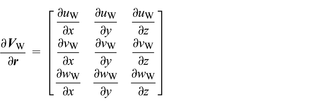
is the spatial gradient of the variable wind field, where
The equation of motion of the center of mass under variable wind field can then be obtained as

where ∑X, ∑Y, and ∑Z are the components of resultant forces; and Θ, Φ are the pitch angle, roll angle of a helicopter, respectively.
When the dynamic equation of translation of the center of mass in equation (1) is replaced with equation (3), a dynamic model of a helicopter in the variable wind field can be expressed as equation (4)

Wind field model
Microburst model
The downward flow caused by the microburst generally lies in the range between several hundred meters and thousand meters. When the downward flow reaches the ground, it starts to spread horizontally and may form one or more horizontal vortex flows around the initial downward flow. 19 Figure 1 shows a sketch map of microburst flow in axial symmetry. The airflow spreading horizontally will generally affect the area at a 1–2 km radius, and the horizontal vortex airflow may extend 600 m high away from the ground.

Microburst airflow in axial symmetry plane.
Soesman model is applied in this work. 11 In this model, the microburst wind field is described as cylinder shape, and the radial fitting and vertical fitting functions are used to define the strength of the wind field. The radial fitting function is expressed as equation (5)

where WR is the horizontal radial wind speed, fR is the radial strength of wind shear, and D is the diameter of the wind field. R represents the horizontal distance between an arbitrary point in the space

Thus, the components of horizontal wind speed are

and

The vertical fitting function is expressed as

where fH is the vertical strength of wind shear, H is the flight height, and VWz is the vertical wind speed.
Equivalent model of helicopter entering and leaving the wind field
Figure 2 shows a sketch map of helicopter forward flight through microburst, where XE, YE, and ZE indicate the ground coordinate system. The helicopter starts to enter the wind field at point A at the moment of tA with speed of

Helicopter forward flight through microburst.
When the helicopter flies between points A and B with high speed, the influence of time derivative of the wind field can be ignored, that is,
The change in the wind field at points A and B can be determined from the form of the gust model. Figure 3 shows three types of equivalent models when a helicopter enters and leaves a wind field. The equivalent models express the abrupt change in the wind field at points A and B with sine, 1-cosine, and slope forms, respectively. The wind model is independent of time when the helicopter flies into the microburst wind field and is determined by equations (6)–(8) based on the helicopter coordinates.

Equivalent models for the helicopter entering and leaving the wind field.
The applicable range of the equivalent models can be referred to the discrete gust model. The 1-cosine equivalent model is proposed to analyze the flight quality of the helicopter under atmospheric disturbance, and the slope equivalent model is recommended to calculate the load of the helicopter. The sine equivalent model is used more to analyze the frequency domain characteristics of the helicopters.
The times
Model validation
Verification of the flight dynamic model
To validate the accuracy of the flight dynamic model, trim analysis is carried out with the UH-60A test helicopter, which has a forward speed from 0 to 92.6 m/s. The joystick positions, including collective pitch control, tail rotor control, longitudinal control, and lateral control, are compared with available UH-60A flight test results. 21 The comparisons are shown in Figure 4.
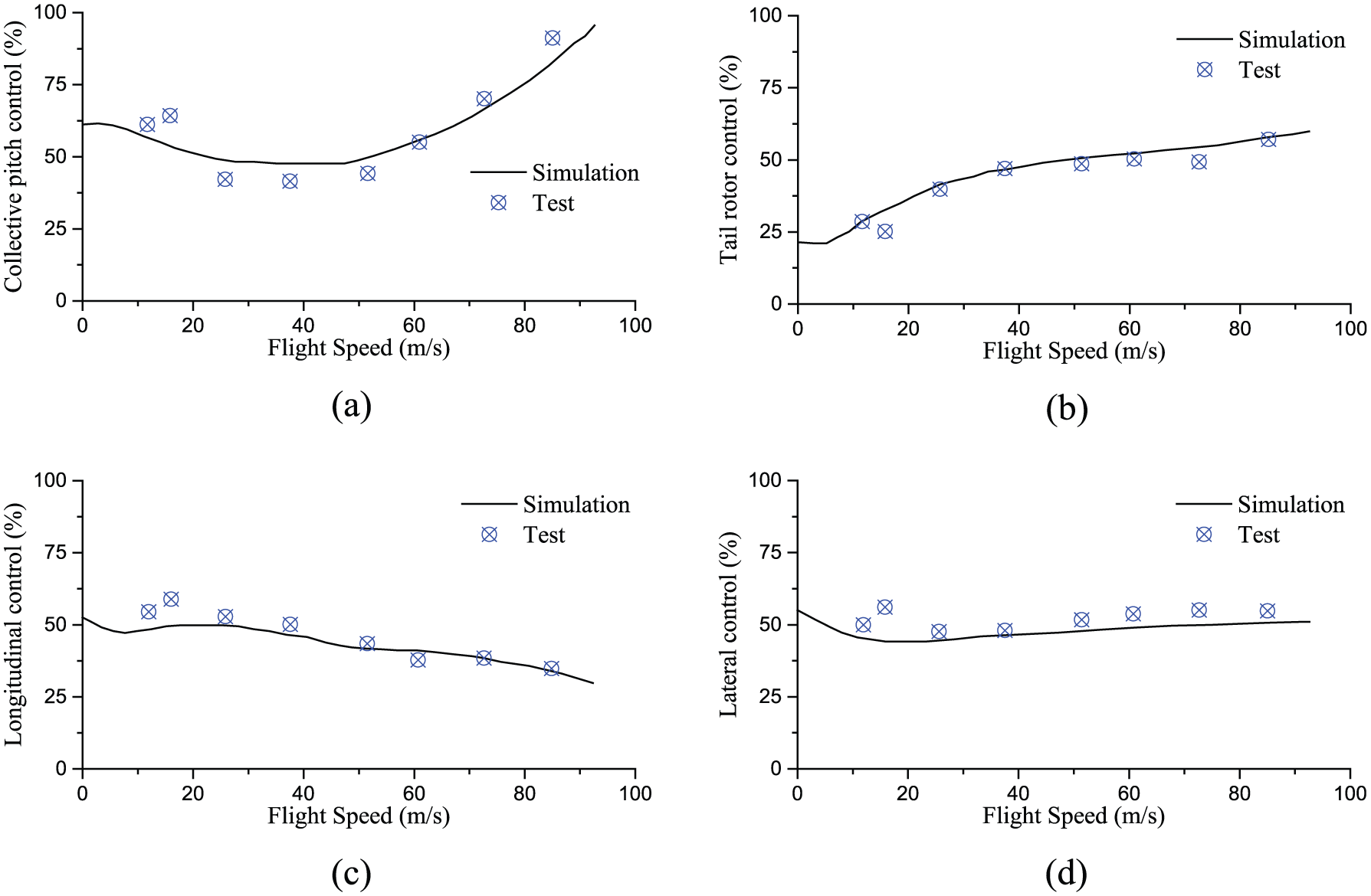
Comparison of trim results between simulation and flight test: (a) collective pitch control, (b) tail rotor control, (c) longitudinal control, and (d) lateral control.
Figure 4 illustrates that the simulation results agree well with the flight test results at medium-speed and high-speed flights, but a discrepancy appears between the results at low-speed flight. The reason for the difference is the difficulty in trimming at low speed in the real flight test, such that the flight test data do not reflect the real flight conditions at the trimming point. Hence, the accuracy of the flight dynamic model is validated and applied to the response analysis in the following sections.
In analyzing the influence of the helicopter control response of collective pitch, the UH-60A helicopter is still used with forward flight speed of V = 185 km/h. According to the flight condition of the flight test, the collective pitch control input by the driver is 1.27 cm upward, and the process of control is shown in Figure 5.
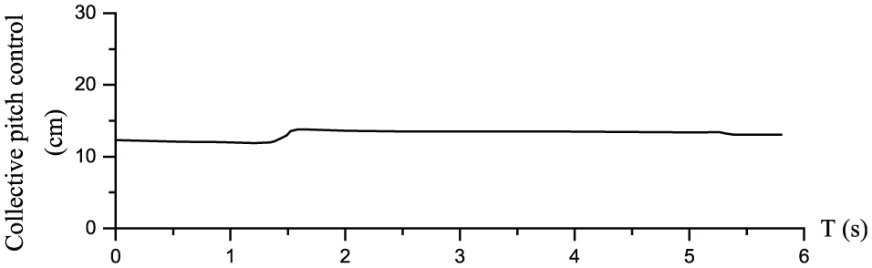
Process of the collective pitch control input.
Figure 6 shows the comparison of the control response by the established model and the flight test data.

Comparison of control response of collective pitch between simulation and flight test data: (a) pitch angle, (b) yaw angle, (c) roll angle, (d) pitch angle velocity, (e) yaw angle velocity, and (f) roll angle velocity.
The results show that the control response of the roll and the yaw angle of the helicopter are close to the flight test results. However, some differences are observed in the pitch angle. The reason is that the aerodynamic data of the fuselage and lifting surface of helicopter use the constant test result in the dynamic simulation. Generally, the model can be effectively applied to the analysis of the helicopter dynamic response under atmospheric disturbances.
Verification of the microburst model
Assume the diameter of the wind field D = 2000 m, radial strength of wind shear fR = 1 m/s, and vertical strength of wind shear fH = 1 m/s. Figures 7 and 8 indicate the vector diagram of the horizontal cross-sectional wind field and the longitudinal symmetrical section wind field in simulation with the Soesman wind model, respectively.

Vector diagram of the horizontal cross-sectional wind field.

Longitudinal symmetrical section wind field.
The simulation results indicate that the Soesman wind field model distributes in axial symmetry and spreads at all sides, and the wind directions at the two sides of the storm are opposite. The wind field spreads to both sides when it reaches the ground and then forms wind fields with a different wind direction. Compared with the practical microburst wind field in Figure 1, the simulation results of the wind field conform to the basic characteristics of the practical wind field and can be used for real-time simulation analysis of the helicopters.
Verification of the equivalent models
To verify the validity of the equivalent models, a type of helicopter model is taken as an example in this article. The model has a flying quality of 5250 kg, rotor wing revolving speed of 31.85 rad/s, and rotor wing radius of 6.75 m.
Assume the helicopter flies with a forward speed of 247 km/h at 600 m altitude and (0 m, 0 m) initial coordinates. The slope equivalent model is used in this example, and the microburst model is the one described in section “Verification of the microburst model.” The coordinate of horizontal center of the wind field is
Comparison of major parameters in the flight process with and without the equivalent model.


Comparison of time derivative in the simulation result with and without the equivalent model: (a) height, (b) lateral displacement, (c) vertical overload ratio, (d) pitch angle, (e) yaw angle, and (f) roll angle.
Table 1 and Figure 9 show that when the helicopter enters and leaves the wind field, the time derivative of wind speed causes increasing rangeability of the flight parameters. For example, the minimum overload ratio is −1.81 with the equivalent model but is −0.13 without the equivalent model, which is close and even goes beyond the safety margin of the structural requirements of some helicopters. The amplitude of flight attitude, including pitch angle, yaw angle, and roll angle, also increases significantly, which causes the increase in the main parameters of the helicopter, including distance of descent, maximum rate of descent, and maximum lateral displacement, all of which will affect the flight safety of the helicopter.
The lift force of helicopter flight is mainly provided by the pulling force of the main rotor. Figure 10 reveals that when the helicopter enters the wind field, the pulling force of the main rotor will undergo a considerable fluctuation, and the same will happen when the helicopter leaves the wind field. However, the change in the pulling force during the flight in the wind field is relatively stable, indicating that the pulling force of the main rotor is sensitive to the change in the wind field caused by the nonlinear characteristics of the helicopter rotor system. Compared to the change in the flight parameters of fixed-wing aircraft, the change in such parameters of the helicopters in response is more serious because the time derivative caused by the change in the wind field has greater influence on the aerodynamic force of the rotor.

Time–domain response upon tension of the main rotor.
Therefore, establishing the equivalent model when the helicopters enter and leave the wind field is necessary so that the flight characteristics of the helicopters encountering microburst can be accurately analyzed.
Flight dynamic simulation
Influence of lateral wind
To analyze the influence of lateral wind in microburst on the flight safety of the helicopter, the following conditions are set: the helicopter flies with a forward speed of 247 km/h at an altitude of 600 m, and it enters the microburst wind field from three positions. The helicopter model and equivalent model of wind field in section “Verification of the equivalent models” are used. The coordinates of the central position of the wind field are

Comparison of simulation results of helicopter flying through the wind field at different positions: (a) flight track, (b) lateral velocity, (c) height, (d) vertical overload ratio, (e) attack angle, and (f) yaw angle.
The response results indicate that the lateral wind caused a certain effect on helicopter flight, and the greatest influence happens to the yaw angle (shown in Figure 11(f)), which causes more complicated lateral movement of the helicopter. Figure 11(c) indicates that the decrease in height in the two groups of simulation with lateral displacement surprisingly reduces. Moreover, when the helicopter passes through the wind field, the more the flight speed deviates from the center of the wind field, the shorter the distance and time of flight in the wind field will be. As shown in this example, the time of the helicopter flight through the wind field is 31.9 s when flight without displacement, and the times in the two other groups are 27.8 and 25.9 s, respectively. Hence, lateral wind has less influence on the flight height of the helicopter and this is mainly determined by the time of helicopter flight through the wind field.
Figure 11(a) shows that although an axisymmetric wind field is adopted, the flight paths with offset distance at both sides are not symmetric. The reason is that the helicopter tail rotor rotation direction is fixed and the effects of the different wind directions on tail rotor aerodynamic performance are no longer the same and the changes in the yaw angle of the helicopter were different. Therefore, the pilot should take the appropriate flight strategy according to different wind directions to secure flight safety.
Influence of downward flow
To analyze the influence of downward flow in microburst on flight safety, the following conditions are set: helicopter flies with a forward speed of 247 km/h at altitudes of 600, 400, 200, and 100 m, respectively, and enters the microburst wind field from the center of the wind field. The helicopter model and equivalent model of wind field in section “Verification of the equivalent models” are also adopted, and the coordinates of the center of wind field are

Comparison of results of simulations adopting different heights: (a) height, (b) vertical velocity, (c) lateral displacement, (d) vertical overload ratio, (e) attack angle, and (f) pitch angle.
The response results indicate that with the increase in height, the rate of descent of the helicopter increases, the changes in the pitch angle become significant, and the reduction in height is higher. Figure 12(d) indicates that with the increase in height, the minimum overload ratio will lessen, which will affect structural safety and bring large pressure to the pilot. However, if the height is too low, an accident may also happen, even though the influence of downward flow is relatively less. As shown in Figure 12(a), when the helicopter flies at 100 m, it may touch the ground after entering the wind field. Therefore, the microburst can significantly damage flight safety in low altitude, and the pilot should avoid entering a microburst when flying at different heights.
Conclusion
The influence of microburst on helicopter flight performance is analyzed through simulations of time–domain response on helicopter forward flight through a microburst wind field. The general conclusions arising from the completion of this work can be summarized as follows:
The time derivative caused by the change in the wind field has considerable influence on the simulation results when the helicopter enters and leaves the wind field. Therefore, the equivalent models can be used to more accurately reflect the flight characteristics of the helicopters flying through a microburst.
Both lateral wind and downward flow in microburst can affect the flight performance of the helicopters. Lateral wind will cause more complicated influences on helicopter yaw characteristic, and downward flow will cause the helicopter to undergo a faster rate of descent with increase in height, thus endangering flight safety.
Large overload will be caused when the helicopters enter the wind field and will get stronger with the increase in the rate of subsidence of the wind field. This outcome will have a certain influence on the structural safety of the helicopter and the handling of the pilot.
Footnotes
Academic Editor: Ramoshweu Lebelo
Declaration of conflicting interests
The author(s) declared no potential conflicts of interest with respect to the research, authorship, and/or publication of this article.
Funding
The author(s) disclosed receipt of the following financial support for the research, authorship, and/or publication of this article: This work was supported by the National Natural Science Foundation of China (no. 11302011) and the Specialized Research Fund for the Doctoral Program of Higher Education (no. 20131102120051).