
Abstract
In the open-die forging process, the forging manipulator must cooperate closely with the forging press. Terrible working conditions of open-die forging have resulted in significant demand on the hydraulic control systems of the forging manipulator. This article analyzes the characteristics of major-motion hydraulic systems with the aim of proposing a novel hybrid serial–parallel heavy-duty forging manipulator. Kinematic and dynamic models of the major-motion mechanism are developed to investigate the control and comply with performance of hydraulic lifting, pitching, and buffering systems. Simulation shows that the three hydraulic systems are coupled in the position and posture control of the clamp. A separate posture control method based on the characteristic of the major-motion mechanism is designed for the hydraulic systems, and the position tracking performance of the hydraulic systems is studied in a stretching process of a plat-tool.
Introduction
The rapid development of nuclear power, hydropower, and ship engineering has resulted in higher demand for heavy forgings worldwide. Heavy load, high quality, and high precision are three main characteristics of open-die forging. A forging manipulator is an auxiliary equipment in open-die forging that adjusts the posture of the clamp and controls the feeding of the workpiece. The ability to operate a forging manipulator is a key factor that affects forging precision and efficiency.
Forging is one of the industry’s most arduous tasks, 1 and the working conditions of the forging manipulator can be quite difficult. Therefore, the driving system must be reliable enough to ensure long working life. Hydraulic systems have been widely used in different industries because of their high power density, fine dynamic response, and ability to produce large force and torque. Most forging manipulators, especially heavy-duty ones, are driven by hydraulic actuators. 2
Parallel mechanisms have the advantages of high stiffness and better payload-to-weight ratio,3,4 which are suitable for distributing heavy loads. Several studies have proposed suitable parallel mechanisms for heavy-duty forging manipulator. CY Yan and F Gao 5 proposed a hybrid serial–parallel mechanism. YD Xu et al. 6 proposed another kind of hybrid serial–parallel mechanism composed of a planar five-bar mechanism and a two-limb parallel mechanism in series. Figure 1 shows a rail-bound forging manipulator with 300 t/750 tm related to load designed by CY Yan et al.7–9 Seven groups of main hydraulic systems (front/rear shifting, front/rear lifting, pitching, clamp rotating, buffering, clamping, and walking) are arranged in the forging manipulator.

Hydraulic systems of a rail-bound forging manipulator designed by SJTU.
The posture of a workpiece refers to its coupling, which driven by several hydraulic systems, among which the walking, rotating, clamping, and front/rear shifting hydraulic systems are independent of one another. However, the lifting, pitching, and buffering hydraulic systems are coupled in the motion and posture control of the clamp, which causes difficulty in the control design. Z Chen et al.10–12 integrated an adaptive robust motion control for master–slave manipulators of multi-degree-of-freedom systems. M Yuan et al. 13 provided a trajectory planning method for biaxial gantry. PH Kim 14 developed a forging pass schedule algorithm to minimize forging cycle time. However, the posture and motion controls of the clamp of a heavy-duty forging manipulator have been rarely studied.
The hydraulic systems function in the motion and posture control mode during intervals in the forging process. During the forging of a workpiece, the clamp must comply with the motions of the upper forging die; otherwise, it may cause damage to the manipulator or unnecessary deformation to the workpiece. Active15,16 and passive 17 suspensive systems are normally used to reduce the effects of vibration and force, and the compliance studies for heavy machinery have been carried out in the last few years. H Shi et al. 18 defined several indices to evaluate the compliance performance for shield machine. J Wang et al. 19 attempted to use adaptive compliance control for a hydraulic manipulator in free forging. Herrmann et al. 20 designed a compliant trajectory tracking controller for a manipulator using operational space and integral sliding mode control. The manipulator may work in active mode to comply with the motions of the forging die while cooperating with the forging press to deform a workpiece. The forces exerted on the clamp are minimized to avoid damage to the mechanism if the hydraulic systems can drive the forging manipulator accurately using the advanced controller.21,22
This study aims to investigate the control characteristic of the clamp and workpiece for a new type parallel forging manipulator. First, the major-motion mechanism is analyzed and hydraulic systems introduced. Then, the co-simulation model of the hydraulic systems and major-motion mechanism is developed with the load model, as well as the kinematic and dynamic model of the mechanism. The relationship between the displacement of the hydraulic cylinders of the major-motion mechanism and posture of the clamp is studied with the co-simulation model. Finally, a characteristic-based control strategy is designed for the posture and position control of the clamp. The stretching forming process of the workpiece is also studied. Results show that the control strategy can effectively control vertical motion but not the horizontal motion control.
Hydraulic systems for the major-motion mechanism
The hydraulic systems of the forging manipulator can be classified into three types. The walking, rotating, and clamping systems rarely have coordination control with the forging press and other systems. The front and rear shifting hydraulic systems cooperate with each other to take or lay down the workpiece before or after the forging procedure and remain motionless during the forging. The lifting, pitching, and buffering hydraulic systems are coupled in the posture and motion controls of the clamp and need to cooperate with the forging press during the forging process. Forces exerted on the manipulator through the manipulation of the workpiece during forging must be minimized to avoid damage to the mechanism, and thus, the lifting system and buffer system must comply with the forging press in the forging process. The performances of the lifting and buffer systems represent the driving ability of the manipulator to some extent.
Major-motion mechanism
The mechanism of the manipulator in the vertical plane, which includes the front/rear lifting, pitching, and buffering hydraulic systems, is called major-motion mechanism and is shown in Figure 2. Each hydraulic system in the major-motion mechanism has two cylinders, the front lifting cylinders Lc4 and the rear lifting cylinders Lc1, which have synchronous movement as they are coupled with beams AD. The cylinders for pitching and buffering system are Lc2 and Lc3.

Front view of the major-motion mechanism.
Hydraulic systems
The forging manipulator studied in this article has four actuators in the lifting system, two front lifting cylinders, and two rear lifting cylinders. Single-acting cylinders are used in the front lifting system because the load of the lifting systems is downward. Double-acting cylinders are used in the rear lifting system to improve driving stability. An accumulator unit is connected to the lower chambers, which can provide a flexible degree of freedom in some special forging conditions for the lifting system. Three proportional direction valves are applied in parallel to address the large flow rate of the lifting system, as shown in Figure 3(a). The schematic of the pitching system is shown in Figure 3(b). A buffering cylinder with four effective chambers is used in the buffering system, as shown in Figure 3(c). The cylinder with special structure can work at buffering or displacement control mode and is selected by a solenoid directional valve.

Schematic of the hydraulic systems: (a) lifting system, (b) pitching system, and (c) buffering system.
Mathematical model of the load and the mechanism
Load from the workpiece
In the forging process, the loads of the forging manipulator can be classified into two types. The first type includes the gravity of the workpiece, the clamp, and other mechanisms, which are constant. The second type refers to the additional force that occurs because of the elastic deformation of the workpiece. The workpiece spreads in the area that is in contact with the dies and the center shaft of the workpiece goes down with the upper die while the upper die presses down. If the motion of the clamp has bias in fitting to the spread speed of the workpiece, force is exerted on the clamp because of the elastic deformation of the workpiece. The horizontal and vertical force analysis is shown in Figure 4.

Elastic deformation of the workpiece.
A Tomlinson 23 describes a single forging pass of a rectangular workpiece by defining the spread coefficient as

where h0 and h1 represent the height of the workpiece before and after forging, w0 is the width of the workpiece before forging, and b represents the length of the workpiece in contact with the dies.
The average width w1 and l1 of the workpiece after forging is as follows


Force is exerted on the clamp in the horizontal as the workpiece spreads in length during the forging.
According to Hooke’s law

where σ and ε represent the stress and strain of the workpiece in horizontal


where FNx is the contact force between the workpiece and the clamp in horizontal, A and lf represent the sectional area and length of workpiece, and Δx is the displacement of the elastic deformation in the horizontal.
Using equations (4)–(6), the force on the clamp in horizontal can be obtained by

In the vertical, the additional force on the clamp is proportional to the elastic deformation of the workpiece
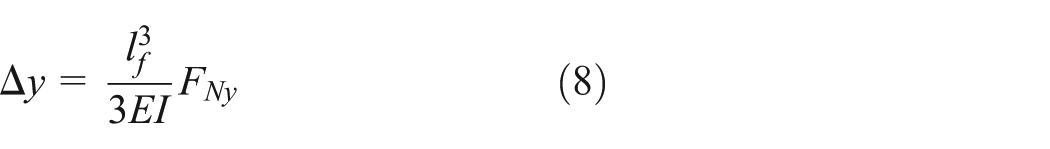
where Δy is the displacement of the elastic deformation in the vertical, lf is the distance between the clamping point and the forging point, E is Young’s modulus of the forged metal, I is the inertia moment around the center axis in vertical cross section, and FNy is the force on the clamp in vertical.
The inertia moment of a workpiece with height h and width w is

Then, using equations (8) and (9), the force exerted on the clamp in the vertical can be obtained by

Assuming that the plastic deformation of the workpiece is equally distributed, the ideal descent velocity of the center axis will be half of the upper die. The displacement of the elastic deformation in vertical can be obtained by
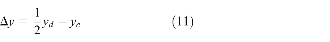
where yd represents displacement of the upper die.
Kinematic model of the major-motion mechanism
A dynamic model should be established to study the characteristics of the major-motion mechanism. The dynamic model can be developed in four steps: forward position kinematics, forward velocity and acceleration kinematics, mass center acceleration calculation, and dynamic equation set.
In forward position kinematics, the posture and position of the clamp are calculated from the displacement of the cylinders. The angles θ1, θ2, θ3, and θ4 should also be obtained for forward velocity and acceleration kinematics.
Similarly, the forward velocity kinematics will be obtained with the differential of the forward position equations. The forward acceleration kinematics will also be obtained with the second-order differential.
Dynamic model of the major-motion mechanism
The 13 components in the major-motion mechanism are shown in Figure 2. Each component can be described with no more than three equilibrium equations (two force equilibrium equations in x- and y-axis, and one moment equilibrium equation); for example, the arm of the clamp, whose force equilibrium is shown in Figure 5, can be described with equation (12). In total, 33 equilibrium equations are developed for all 13 components, from which the contact forces between components and input forces from the driving systems can be obtained with the matrix operation of the equations


Diagramed force equilibrium for the arm of the clamp.
Characteristic study of the major-motion mechanism
Co-simulation model
A simulation of the structure or hydraulic control system can yield the valuable information for other researchers, but the adoption of a multi-domain simulation can provide more reasonable results. 24 In the development of the mechanic–hydraulic deformation co-simulation model, the driving force is set as input data and the displacement, velocity, and acceleration as output data for the hydraulic systems. In the kinematic model, the input is the motion of the cylinders and the output includes all motion parameters of the components. In the dynamic model, the input is the motion of the mechanism and the output is the driving force of the hydraulic systems. In the deformation model of the workpiece, the input is the motion of the clamp and the forging press, whereas the output is the additional forces on the clamp. The schematic of the co-simulation model is shown in Figure 6.

Schematic of the co-simulation model.
Dynamic characteristics of the hydraulic system
The equivalent load of the mechanism and workpiece can be calculated for the hydraulic systems using the co-simulation mathematical model, as shown in Table 1. The inertia loads of the mechanism and workpiece are both very heavy, especially for the buffering system in which the inertia load of the mechanism can reach more than 2000 t. The inertia load has a significant effect on the dynamic behavior of the hydraulic system, and the natural frequency of a valve-controlled cylinder hydraulic system can be obtained easily by linearizing the system. Assuming that the elasticity modulus of the transmission fluid is 700 MPa, the natural frequencies of the major-motion hydraulic systems can be calculated using the structure parameter of cylinders, as shown in Table 2. The natural frequencies are quite low (see Table 3), especially for the buffering system in which the frequency is only 2 Hz when the forging manipulator is in the maximum load. The underdamping character may also cause overshoot and oscillation to the hydraulic systems, resulting in stability and tracking precision problems. 25
Equivalent load of the hydraulic systems in initial position.

Dimension of the cylinders.

Natural frequency of the hydraulic systems.

Control strategy design
The relationship between the posture of the clamp and the displacements of the hydraulic cylinders is deduced using the co-simulation model, as shown in Figure 7. The three-state parameters of the clamp are related to the three displacements of the cylinders, which means they are coupled in the posture control of the clamp. The displacement of the lifting cylinders has a significant relationship with the y-axis displacement of the clamp, has little relationship with the x-axis displacement, and is almost unrelated to the pitching angle of the clamp. Similarly, the displacement of the buffering cylinders has a significant relationship with the x-axis displacement of the clamp, and the displacement of the pitching cylinders is related to all three-state parameters of the clamp. In this condition, the closed-loop displacement control of the cylinders is not a good method to control the posture of the clamp precisely. A closed-loop posture control method is designed based on the characteristics of the major-motion mechanism to control the clamp and workpiece properly, as shown in Figure 8. In the posture control system, the three hydraulic systems are working in coordination to realize every motion of the clamp and the workpiece.
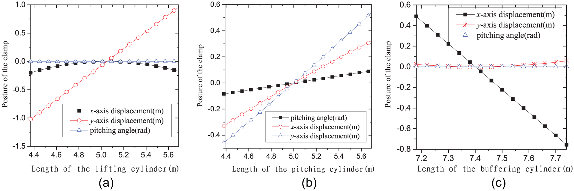
Relationship between the posture of the clamp and the displacements of the cylinders: (a) lifting cylinder, (b) pitching cylinder, and (c) buffering cylinder.

Closed-loop posture control for the major-motion hydraulic systems.
Case study in stretching forming process
Stretching forming process of the workpiece
The forging manipulator cooperates with the forging press in the stretching forming process of a workpiece, as shown in Figure 9. The top right of the figure shows the displacement of the forging manipulator in the x-axis, whereas the bottom right shows the displacement of the upper die in the y-axis. In period b–e, the upper die and workpiece are separated while the forging manipulator carries the workpiece and moves forward in the x-axis. In period e–g, the workpiece stretches plastically as the upper die presses and the forging point of the workpiece remains still in x-axis when the center shaft moves downward. In period g–a, the upper die returns upward and the workpiece feeds forward.

Cooperation of the forging manipulator and the forging press.
The dimensions of the workpiece and motion of the forging die in the stretching forming process are shown in Table 4. The length, width, and height increments of the workpiece are shown in Figure 10 along with the forging process. The workpiece spreads in both length and width.
System parameters of the stretching forming process.


Dimension increments of the workpiece in stretching process.
Simulation results
Theoretically, the ideal backward displacement of the clamp in the horizontal is half the length increment of the workpiece and ideal downward displacement of the clamp is half of the upper die. The ideal displacement and velocity of the clamp are shown in Figure 11.

Ideal trajectories of the upper die and the clamp (m, m/s).
In the simulation, a closed-loop posture control is designed for the clamp. The vertical trajectory input is from the upper die of the forging press, whereas the horizontal trajectory input is from the deformation calculation of the workpiece. Conventional proportional–integral–derivative (PID) control is applied in the system, the parameters for the PID control are set with trial-and-error method, and the well-tuned gains for the lifting system are KP = 200, KI = 100, and KD = 10 and for the buffering system are KP = 7, KI = 2, and KD = 0.2.
The displacement tracking results are shown in Figure 12. The trajectory tracking in y-axis is close to the desired one, but the tracking error in x-axis is approximate to half of the whole displacement range, which needs to be improved. The fluctuating forces of the lifting and buffering system are 800 and 200 kN (see Figure 13), and both the driving and fluctuating forces are affordable for the hydraulic systems. The load of the hydraulic lifting system is related to the dimensions of the workpiece; if the workpiece is shorter or higher, the force will fluctuate more violently. Besides, there will also be greater exerted forces if the stroke of the forging press is longer or the elongation of the workpiece is larger. At present, the cooperation between the forging manipulator and the forging press is still controlled manually by the operator, and the forces exerted on the forging manipulator may affect the clamp and hydraulic systems. In this respect, closed-loop posture control in the vertical should be considered for the forging manipulator studied in this article.
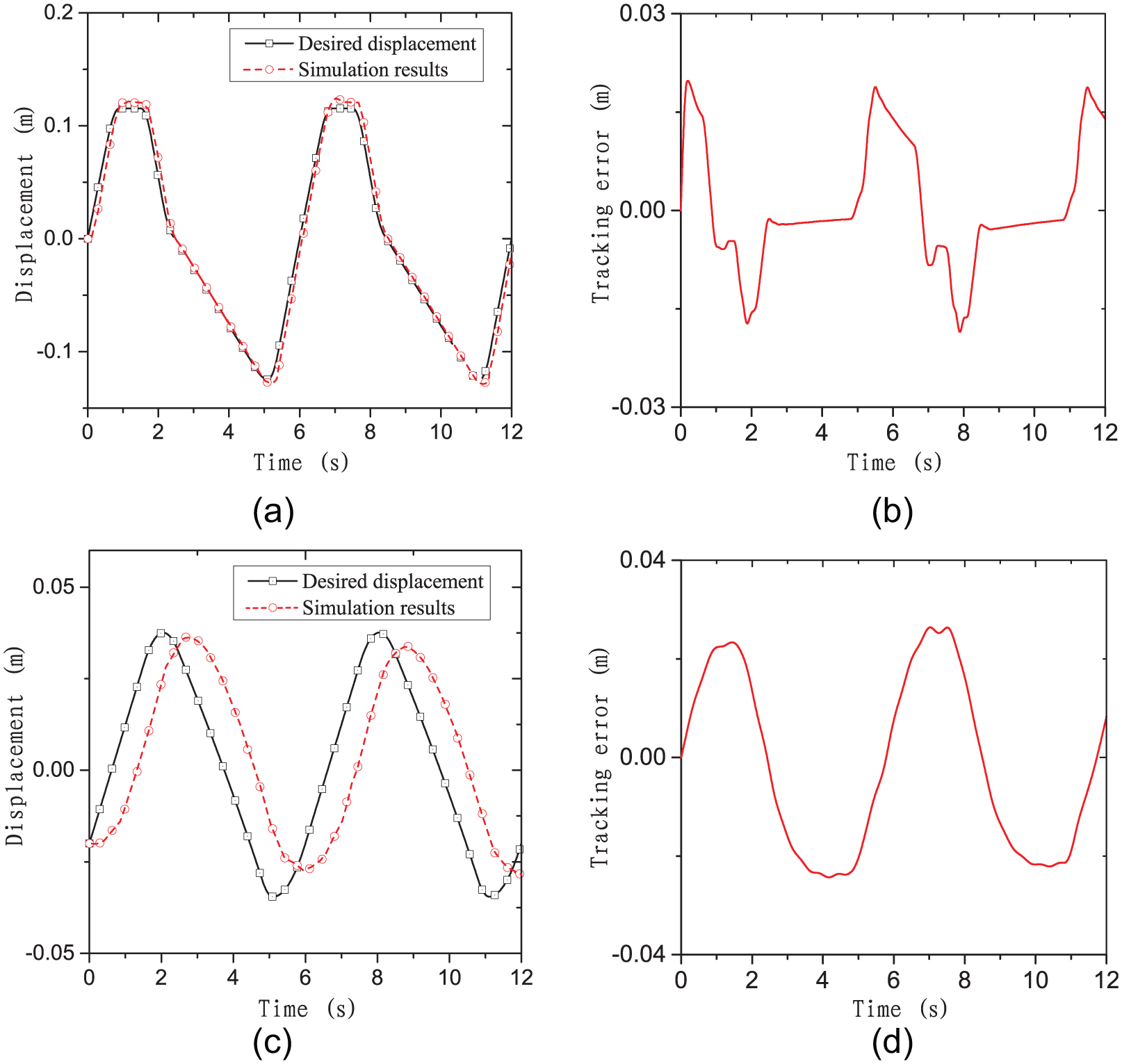
Tracking performance of the clamp: (a) displacement in y-axis, (b) tracking error in y-axis, (c) displacement in x-axis, and (d) tracking error in x-axis.
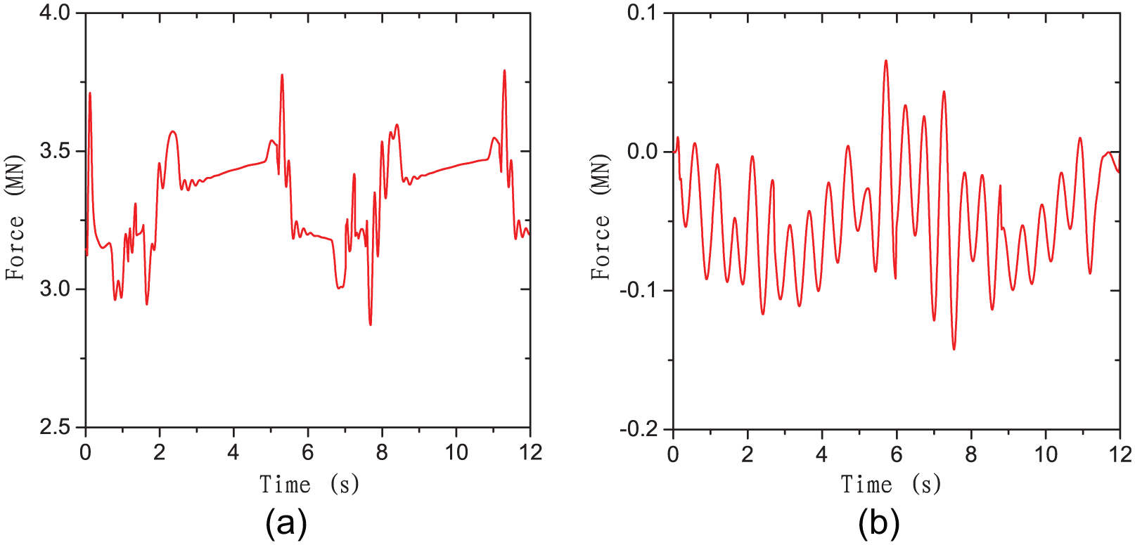
Loads of the hydraulic systems: (a) load of the lifting system and (b) load of the buffering system.
Conclusion
The structural features of a hybrid serial–parallel open-die forging manipulator are analyzed, and the coupling relationship among the lifting, pitching, and buffering systems in the posture control of the clamp is discussed. The deformation model of the workpiece and the kinematic and dynamic model of the major-motion mechanism are developed to investigate the characteristics of the hydraulic systems. The inertia loads of the hydraulic systems are quite heavy, causing the natural frequencies of the systems to become very low, especially for the buffering system, which is only 2 Hz when the clamp is carrying a heavy workpiece.
According to the cooperation work mode of the forging press and manipulator, a closed-loop posture control method is designed for the clamp based on the coupling characteristics of the major-motion hydraulic systems. A stretching process of a plat-tool is studied using co-simulation model. Results show that the position tracking precision of the clamp in y-axis is enough to comply with the forging press, but the tracking precision in x-axis is accurate. In this condition, the buffering system is more effective when working at passive compliance than active tracking compliance.
Footnotes
Academic Editor: Zheng Chen
Declaration of conflicting interests
The author(s) declared no potential conflicts of interest with respect to the research, authorship, and/or publication of this article.
Funding
The author(s) disclosed receipt of the following financial support for the research, authorship, and/or publication of this article: This work was supported by the National Natural Science Foundation of China (Grant Nos 51405054, 51475064, and 51275063), the Fundamental Research Funds for the Central Universities (Grant No. 3132016355), Doctoral Scientific Research Foundation of Liaoning Province (Grant No. 20141104), the National Key Technology Support Program (No. 2014BAB12B00), and the MOT Science and Technology Project (Grant No. 2014328204050).