
Abstract
Thermal engines based on pressure gain combustion offer new opportunities to generate thrust with enhanced efficiency and relatively simple machinery. The sudden expansion of detonation products from a single-opening tube yields thrust, although this is suboptimal. In this article, we present the complete design optimization strategy for nozzles exposed to detonation pulses, combining unsteady Reynolds-averaged Navier–Stokes solvers with the accurate modeling of the combustion process. The parameterized shape of the nozzle is optimized using a differential evolution algorithm to maximize the force at the nozzle exhaust. The design of experiments begins with a first optimization considering steady-flow conditions, subsequently followed by a refined optimization for transient supersonic flow pulse. Finally, the optimized nozzle performance is assessed in three dimensions with unsteady Reynolds-averaged Navier–Stokes capturing the deflagration-to-detonation transition of a stoichiometric, premixed hydrogen–air mixture. The optimized nozzle can deliver 80% more thrust than a standard detonation tube and about 2% more than the optimized results assuming steady-flow operation. This study proposes a new multi-fidelity approach to optimize the design of nozzles exposed to transient operation, instead of the traditional methods proposed for steady-flow operation.
Keywords
Introduction
Pressure gain combustion, and in particular detonation-based thermal engines, offers increased thermal efficiency compared to the traditional Joule–Brayton cycle.1,2 In a pulsed detonation combustor, the combustion process evolves from deflagration to detonation along a tube, resulting in a very energetic detonation front moving at supersonic velocities toward the open end of the tube. Already in 1998, Cambier 3 had identified the importance of optimizing the nozzle geometry to maximize the potential engine thrust. Because the detonation process is characterized by supersonic flows, one would conclude that divergent nozzles would outperform other types of nozzles, allowing the further expansion of the supersonic combustion gas. Daniau et al. 4 demonstrated experimentally that a nozzle with a short, abrupt expansion increases the impulse and the refilling frequency. In contrast, Ruhul et al. 5 investigated numerically three nozzle geometries including straight, converging/diverging, and diverging and concluded that for all of them, long nozzles should be selected to sustain detonation for a longer duration, allowing longer periods with positive thrust. Kailasanath 6 noted that an increase in the impulse is achievable by reshaping the nozzle, without penalizing the detonation tube refilling frequency. Based on the experimental comparisons of several supersonic nozzles, Falempin et al. 7 concluded that a bell-shaped nozzle delivers the maximum thrust.
Levin and Manulovich 8 performed a nozzle-shape optimization of conical and parabolic nozzle shapes using analytical expressions based on infinitely thin detonation waves. Billings 9 parameterized a two-dimensional (2D) nozzle using cubic functions and performed the optimization using a genetic algorithm and inviscid evaluations, concluding that supersonic diverging nozzles are the best to maximize the thrust. However, the previous literature on supersonic nozzle design relies fundamentally on steady-flow assumptions.
As the open literature on pulse detonation nozzles focuses on simple geometries and inviscid solvers, a new design approach for pulsed regime and evaluations of the reacting flow was needed. The aim of this work is to optimize nozzles exposed to low-frequency detonation pulses with a multi-stage methodology. The first step of the optimization process is based on steady assumptions to reduce the number of parameters in the design of experiments. A subsequent full unsteady optimization is performed and followed by a detailed analysis under reacting flow conditions. The emphasis of this work is on single-cycle and low-frequency (below 1 Hz) unsteady nozzle behavior and performance. It is worth noting that according to Ma et al., 10 at frequencies above 100 Hz, the nozzle performance may be substantially altered; hence, we invite the readers to test the present approach to design and assess nozzles operating at higher frequencies.
Numerical approach to optimize the nozzle
Geometry parameterization and mesh generation
The nozzle geometry is defined by a Bezier curve, which is parameterized by the coordinates of the control points. Once the optimizer selects the coordinates of the control points, a MATLAB script generates the nozzle geometry. The geometry is subsequently imported into the meshing software GAMBIT to generate the computational grid.
In the first stage, the nozzle was optimized for steady-flow conditions. Figure 1(a) outlines the parameterization during this steady aerodynamic optimization phase, which consists of five control points. The nozzle geometry design space was allowed to change widely, allowing the generation of convergent, convergent–divergent, and divergent shapes. The use of convergent–divergent, straight, or divergent nozzles for pulsed detonation requires compromises regarding the different objectives: refilling frequency, specific thrust, and thermal aspects. In this research, at the very low frequencies considered, the objective is focused only on aerodynamic aspects.
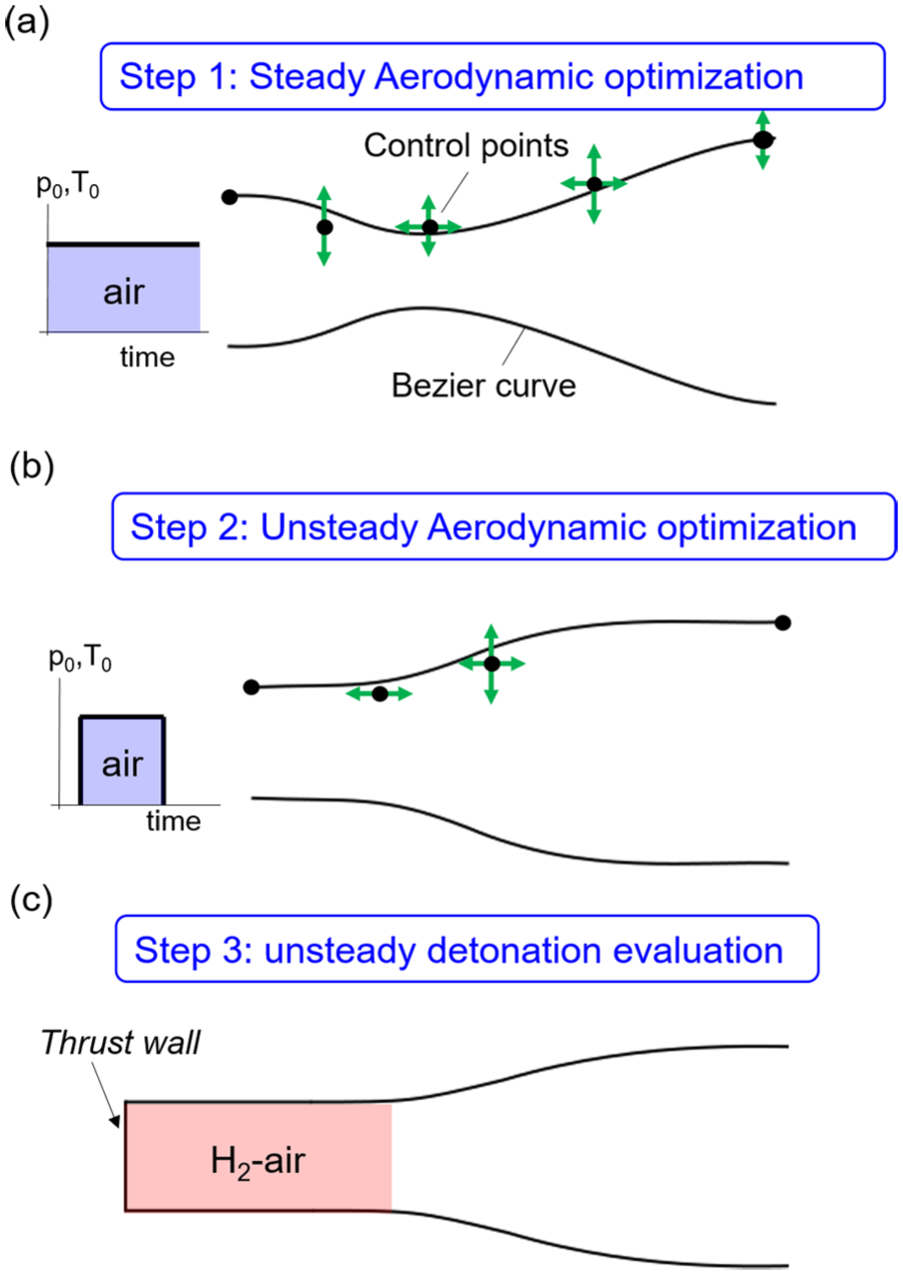
Three-level optimization approach: (a) steady-flow optimization, (b) optimization considering unsteady flow, and (c) detonation combustion modeling.
In the second optimization step, presented in Figure 1(b), the geometry is further refined considering a transient pulse. This stage is based on the previous results in terms of nozzle type (convergent, divergent, and so on), and only four control points are used to define the geometry. Interestingly, the optimizer discarded some common geometries employed as baseline shapes in several prior studies, selecting smoothly profiled contours of divergent nozzles that ensure best aerodynamic performance.
In the third phase, the optimized geometries are evaluated considering the combustion process. During this phase, the steady- and unsteady-optimized geometries are compared to two baseline cases considering reacting flows (Figure 1(c)), namely, a straight duct and a contoured nozzle designed with the method of characteristics (MOC). 11
Optimization tool
The nozzle optimization is based on the computer-aided design optimization (CADO) tool, an in-house optimization code based on evolutionary algorithms, developed at the von Karman Institute.
12
Evolutionary algorithms are population-based methods where individuals evolve over a search space and are altered by mechanisms such as mutation, crossover, and selection. The individuals, namely, the set of parameters that characterize the nozzle shape, associated with a higher performance (fitness) have more chance to survive and get reproduced. The optimization loop automatically generates the new individuals, assessing their performance with computational fluid dynamics (CFD), by combining the geometrical features of the superior performing nozzles. The optimization aimed to maximize the nozzle exit force:
The optimizer changed the geometry by selecting the coordinates of control points of the Bezier curves (Figure 1(a) and (b)). A wide design space was explored via a differential evolution algorithm. A CFD simulation was performed for each design selected by the optimizer. No surrogate models were used during the optimization, allowing convergence in fewer iterations.
Numerical solver
The aerodynamic flow evaluation was performed with the commercial CFD software CFD++ of Metacomp Technologies adapted to utilize an unsteady Reynolds-averaged Navier–Stokes (URANS) density–based solver equipped with the Harten–Lax–van Leer–contact (HLLC) scheme. For numerical stability, the multi-dimensional total variation diminishing (TVD) polynomial interpolation was used. The time discretization was performed with a dual time-stepping procedure through an automatic Courant–Friedrichs–Lewy (CFL) adjustment procedure (ACAP) which ensured the stability and convergence for large time steps. The two-equation k–ω shear-stress transport (SST) turbulence closure was selected. This model combines the capability of k–ω to predict regions with adverse pressure gradients and the accuracy of the k–ε to model the turbulence level in free-stream regions. The actual real gas effects in the combustion process were considered in the final stage of the design, during the study of the detonation process, as described in the following sections. However, the ideal gas formulation with gas properties dependent on the flow temperature was used in the steady and unsteady optimization stages.
Computational domain
The numerical domain for the steady and unsteady optimization consisted of a structured grid composed of approximately 50,000 cells in a 2D axisymmetric domain. The y+ was kept below 1 in the near wall region in order to resolve the viscous sublayer. The smallest grid closest to the wall had a thickness in the order of 10−6 m, and the expansion ratio for successive cell size was set to 1.2. The small grid size allowed to avoid the use of wall functions, which was preferred to resolve the actual flow physics. Figure 2 depicts the entire numerical domain used in the time-averaged analysis. The domain used for the unsteady optimization was further extended with a plenum connected to the nozzle exit.
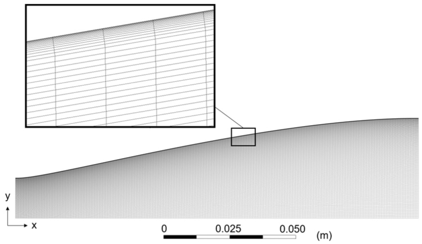
The 2D axisymmetric computational domain for the steady and unsteady optimizations (bottom) and detail of the grid refinement along the outer wall (top).
Aerodynamic optimization: steady and unsteady
Steady-flow optimization
The nozzle geometry was parameterized by a fourth-order polynomial Bezier curve defined by five control points. An angle of 0° was imposed at the nozzle inlet (Figure 1(a)) to ensure a smooth transition from the detonation tube to the nozzle section. The Bezier control points were allowed to vary within wide bounds in order to enable the generation of convergent–divergent, divergent, and divergent–convergent nozzles. The inlet total pressure was 5.05 × 10⁶ Pa and the inlet total temperature was 3869 K, and supersonic outflow conditions were set at the nozzle exit. The optimization objective in this phase is to maximize the steady force. Figure 3 presents the nozzle outlet force evaluated during the optimization procedure. After 88 iterations, or direct CFD evaluations, the force reached a level of 5.69 kN and the optimization process was stopped once the force did not improve any further within 0.02%. Figure 3 shows the convergence history of the steady-flow optimization process. The optimal design was found to be a divergent nozzle with an exit radius corresponding to the maximum allowed by the design space (

Optimization convergence history for the steady-flow optimization.
MOC for steady analysis
Rao
11
developed an analytical method based on the MOC to optimize a nozzle shape for maximum thrust. The same author later developed a faster procedure that relies on tabulated charts of inlet and outlet angles of the nozzle profile.
13
The geometry designed with the MOC was approximated by a second-order quadratic polynomial as recommended by Rao.
13
The nozzle had length

Mach number contours for three designs: (a) MOC nozzle, (b) steady-optimized geometry, (c) unsteady-optimized geometry at a given instant, and (d) geometry of the nozzle profiles obtained during this study.
Unsteady-flow optimization
During the unsteady force optimization, a flow step was implemented as an inlet boundary condition to the parameterized nozzle. The objective was to maximize the overall time-averaged exit force. A step in pressure and temperature was imposed at the nozzle inlet in order to simulate the aero-thermal features of the detonation flow conditions. The flow inside the nozzle was initially set to 0.63 × 10⁶ Pa and 507 K. The inlet air pulse had a maximum total pressure value of 4.20 × 10⁶ Pa and maximum total temperature value of 3700 K and was purged for a duration of 0.054 ms. Figure 5(a) and (b) shows the transient total pressure and total temperature imposed at the nozzle inlet, respectively.

(a) Total pressure and (b) total temperature inlet conditions for the unsteady optimization and (c) results of ratio between exit force and averaged inlet total pressure for the optimal shape.
During the steady optimization as well as in the MOC method, divergent nozzles were identified as the preferred geometries. Therefore, in this phase of the optimization, to define divergent nozzles, the nozzle geometry was parameterized with four Bezier control points (Figure 1(b)). The optimization was completed when the difference in time-averaged force between two consecutive populations was less than 1.2%. In the final nozzle, the optimal time-averaged force reached
The Mach number contours of the aero-thermal pulse flowing through the exit (t = 0.1 ms) are depicted in Figure 4(c). The complex flow field behind the pulse front is shown to be uniform at the nozzle exit, reaching a Mach number of 3.2. Figure 4(d) compares the different nozzle geometries obtained during this study. Interestingly, both the MOC-based nozzle and the unsteady-optimized geometries have a similar shape for the first 30% of the axial length.
Unsteady nozzle performance with detonation
Description of the solver
Deflagration-to-detonation transition (DDT) is a complex multi-physical phenomenon, involving gas dynamics, heat transfer, and flame instabilities.14–16 Due to the high Reynolds number at which DDT occurs, the problem is challenging to resolve numerically. However, the prior literature 17 indicated that not all microscopic scale phenomena are strictly significant for an accurate representation of the macroscopic features of the DDT. The accuracy of the under-resolved DDT simulations was proven by Thomas. 18 In order to simulate the detonation phenomena, the DDTFoam solver, developed by Ettner 17 and available in the open-source platform OpenFOAM, was selected. DDTFoam is a density-based URANS solver for compressible reactive flows. The convective fluxes are computed with the HLLC scheme with multi-dimensional slope limiters. The reaction mechanism of hydrogen and air is modeled by the O’Conaire reaction scheme, 19 and the material properties are selected from the Chemkin Database 20 via look-up tables. The Sutherland correlation 21 is used for the evaluation of the molecular transport coefficients. The deflagration combustion is modeled through the Weller model (based on a reaction progress variable), and the detonation is modeled based upon the auto-ignition delay time.
Numerical domain
In order to simulate the three-dimensional (3D) flow features, a 3D domain of the nozzle geometry was generated. The domain consisted of a quarter of the revolved nozzle contour and partially filled by H2–air mixture (Figure 6). One end of the detonation tube was closed (thrust wall) and the other end was connected to the exit nozzle. The tube was partially filled with stoichiometric H2–air mixture, whereas the contoured section was filled with water vapor and N2 at the relative concentrations of the combustion products, as sketched in Figure 6. Initial flow velocity, total pressure, and static temperature were set to 515 m/s, 0.63 × 10⁶ Pa, and 388 K, respectively, and were imposed to be uniform in the whole domain. The initial conditions were set to the levels delivered by the radial compressor located upstream of the detonation tube in the present research. The described set-up was chosen in order to simulate the engine configurations allowing the expansion of the detonation products in the nozzle (i.e. no chemical reactions occurred within the nozzle). A no-slip condition was applied to all walls, and a symmetry condition was set on the side faces of the nozzle quadrant. A supersonic outlet was imposed at the domain exit to avoid potential spurious reflections coming from the domain exit. To this end, no boundary conditions were needed at the outlet, and the flow properties were extrapolated from the internal field. A good numerical stability of the DDTFoam solver was ensured by imposing a CFL number lower than 1. More specifically, a CFL-sensitivity study was performed, and the solution was found to be unaffected for CFL numbers smaller than 0.5. Consequently, this value was used for all simulations with detonation.
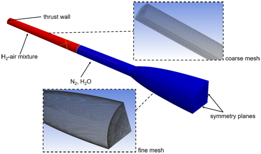
Numerical domain for the combustion analysis and mesh topology.
The computational domain was divided into two parts: a straight tube, where the combustion was modeled, and the shaped nozzle, where only gas products expanded. The straight nozzle was meshed with a structured grid having maximum size of 1 mm. In the shaped nozzle, the mesh was further refined in order to predict the complex flow characteristics. This dual-mesh step was implemented in OpenFOAM by means of the function MapFields. The sketch of the computational domain and mesh topology is shown in Figure 6.
It is worth clarifying that the mesh size of 1 mm in the straight tube was sufficiently small to predict the energy release through the detonation process, as reported by Ettner 22 and validated through the comparison with the prior experiments as reported in the following section.
Validation of the numerical model
The numerical model was validated against experimental measurements of DDT in a tube found in the literature. 17 A 2D rectangular tube was simulated (Figure 7(a) and (b)). The tube had a length of 5.4 m and a height of 60 mm and was equipped with squared obstacles of 9 mm height, spaced by 300 mm over 2.1 m length of the channel. On the left-hand side of the tube, a closed wall (thrust wall) was imposed, while the right-hand side was opened to atmosphere to allow the discharge of the detonation wave. A blockage ratio of 30% was considered according to the value used in the experiments. The tube was filled with homogeneous H2–air mixture with a hydrogen concentration of 25% in volume. The mixture was ignited in a small region close to the thrust wall on the left (Figure 7(a)). The initial temperature of the mixture was 293 K and the initial pressure was 1 bar.

(a) Schematic of the channel geometry, (b) detailed view of the numerical domain, (c) comparison between experimental 17 and numerical results of the flame position in time, and (d) detail of the detonation cell structures for a test-case pipe of 0.4 m width.
Along the initial section of the tube, a low flame velocity indicated pure deflagration (Figure 7(c)). Due to the presence of the notches, the turbulent mixing led to the acceleration of the flame front. At a distance of 2 m from the ignition wall, the flame speed showed a sudden increase, indicating that the full transition to detonation combustion was occurred (also visible in Figure 7(b)), and the Chapman–Jouguet conditions were established. The numerical results agreed with the experimental data with a maximum difference of 2% in the Chapman–Jouguet velocity corresponding to the actual flow conditions.
A further analysis concerning the capability of the solver of capturing complex detonation structures was performed for a pipe of 0.4 m width. The resultant pressure field at the outlet (3.3 m) around the detonation wave is shown in Figure 7(d). An established detonation front with typical cell structure involving Mach stem and oblique shocks interaction was observed to take place at the domain outlet. The predicted detonation cell width was 30 mm, which was found to be in agreement with Giurao et al. 23
Pulse detonation analysis
The three nozzle geometries (Figure 4(d)) and the straight outlet were simulated under detonation conditions. A single detonation pulse was generated at the thrust wall in the straight section. Figure 8(a) shows the axial velocity contours at different time steps for the unsteady-flow optimization nozzle case. After the ignition, a shock-induced detonation wave was observed. A stable detonation front was generated and propagated through the fresh mixture. After 0.2 ms, the mixture was completely consumed and only gas products expanded within the nozzle with increased axial flow speed. At t = 0.26 ms, a high-density pulse traveling at high Mach number was observed inside the divergent nozzle (Figure 8(b)). Subsequently, the high-velocity wave reached the exit of the nozzle at 0.32 ms. At the same instant, the passage of the shock wave resulted in a strong pressure gradient in the near wall region close to the outlet (Figure 8(c)) leading to a mild flow separation (Figure 8(a), t = 0.38 ms). However, the separation was observed to take place at the end of the pulse, causing a negligible contribution to the overall force.

(a) Axial velocity contours for seven different time steps for the unsteady flow–optimized profile, (b) details of density contours, and (c) Mach number contours at t = 0.20, 0.26, and 0.32 ms.
The performances of the three different configurations under detonation conditions in conjunction with the straight outlet were compared in terms of force at the nozzle exit surface. Figure 9(a) depicts traces of the mass-averaged force at nozzle exit for the three nozzle geometries simulated as well as the straight outlet. Figure 9(a) also shows that each nozzle configuration resulted in different blowing periods. The MOC design and the optimized profile for unsteady flow showed a similar pulse period of about 0.3 ms, with a maximum transient exit force of 23 × 103 N. The steady flow–optimized configuration showed narrower pulse time with higher peak in the transient exit force (27 × 103 N), while the straight duct could generate fluidic force during 0.4 ms with a maximum force of only 12 × 103 N.

Thrust generated by a straight duct, MOC design, optimized for steady flow and unsteady flow: (a) nozzle exhaust force evolution in time and (b) integrated force all along the detonation pulse.
The performance of the detonation tube was enhanced by up to 80% in terms of time-averaged force by just adding a shaped nozzle with respect to the straight duct application. The MOC nozzle showed 1.5% increase in the time-averaged exit force compared to the optimized nozzle for steady flow. Interestingly, the optimized nozzle for unsteady flow delivered about 2% more time-averaged force than the MOC nozzle (Figure 9(b)).
Conclusion
This article addresses the void of optimization tools for nozzles exposed to transient supersonic flows. Prior literature presented traditional shapes such as straight, conical, and parabolic nozzles or used steady assumptions in the design methodology. The new design procedure consists of a multi-stage approach utilizing a single-objective optimization. In the first step, using inexpensive 2D steady Navier–Stokes evaluations, we explored a broad design of experiments, from converging–diverging nozzles to diverging–converging, to select optimal geometries in terms of delivered axial force. This step suggested that a divergent shape was preferable. In the second step, with a narrowed population, we optimized the nozzle to maximize the time-averaged force when the nozzle was exposed to a flow pulsation. The optimizer performed direct evaluations of the nozzle performance with 2D URANS simulations. The optimized design was subsequently assessed under detonation conditions with a 3D detonation flow solver. The optimized designs were compared with a simple tube and the geometry obtained with MOC, burning a stoichiometric, homogeneous hydrogen–air mixture. The design approach is shown to successfully enable increased thrust by 2% compared to the steady design. This article also presents the flow characterization in supersonic nozzles exposed to single pulses. A high-pressure and high-density pulse generated by the detonation was observed to flow through the nozzle with increasing axial velocity while interacting with the local boundary layer. This led to flow separation at the end of the pulse.
Footnotes
Appendix 1
Acknowledgements
The authors would like to acknowledge Maxwell Adams and Alex Bucknell from the Department of Engineering Science of the University of Oxford, who assisted in the proofreading of the manuscript.
Academic Editor: Bo Yu
Declaration of conflicting interests
The author(s) declared no potential conflicts of interest with respect to the research, authorship, and/or publication of this article.
Funding
The author(s) disclosed receipt of the following financial support for the research, authorship, and/or publication of this article: This work was performed within the Tangential Impulse Detonation Engines (TIDE) project supported by the EU within the 7th Framework Program, under the grant agreement number 335091. Consequently, the authors would like to express their gratitude to the European Commission for the financial support during the execution of this research.