
Abstract
Both the process of eliminating the clearance in joints and the contact–impact process involve movement of a clearance mechanism, which may reduce transmission accuracy and lengthen the response time. An appropriate continuous contact force model is able to describe the contact phenomena of a joint with clearance in a facile manner. However, two main problems still should be solved in building the continuous contact force model. First, the elastic force parts in previous continuous contact force models for a revolute joint were established by amending the force exponent of the Hertz spherical contact model or by the modified Winkler contact model. Nevertheless, the force exponent is usually given by experience, and the thickness of the elastic layer in the Winkler theory is difficult to determine. Second, for the previous damping force parts of a revolute joint, the hysteretic damping coefficients were obtained by substituting the stiffness coefficient with the contact stiffness of revolute joint directly instead of using the energy conservation method for the complicated form of elastic force model. A feasible continuous contact force model based on a fitting method was proposed to avoid these problems. According to the experimental results, the continuous contact force model can be used to predict the contact characteristics of a planar revolute joint in a facile manner.
Keywords
Introduction
Because of the existence of clearances, the phenomena of contact and separation occur in the joints of a mechanism inevitably, resulting in the following two processes: the eliminating clearance process and the contact–impact process. The eliminating clearances process will result in a certain deviation between the actual and expected locations of links, possibly resulting in a certain transmission error of the mechanism. The response speed of mechanism will be reduced because of the wasted time during the process. Moreover, the contact–impact process may generate a great contact force, which intensifies the instability of the moving mechanism.1–5 The contact–impact force model plays key roles in predicting the contact characteristics of the joints with clearances and reducing the negative influences of clearance joints on the dynamic behavior of the mechanism.6–9
The contact duration is assumed to be extremely short in the contact models based on the piecewise method, leading to the rapid changes in the contact parameters. The contact bodies are all considered as truly rigid bodies in the piecewise contact models.10–12 Thus, there is no deformation in the contact surfaces, in contrast to the actual contact situation of contact objects. In the continuous contact force (CCF) models, it is assumed that a spring–damper element exists in the contact surfaces of bodies. Given the geometrical and the material properties of the contact bodies in detail, the contact model based on continuous method can describe contact–impact processes more effectively and exactly than those based on the piecewise method.13–18
The CCF models were denoted as a continuous nonlinear function of the indentation and the relative contact velocity. The model was expressed as an additive form of the elastic force and the damping force. 19 In the first part, the elastic force can reflect the abilities of contact bodies in terms of storing and releasing strain energy. In addition, the damping force part can reflect the dissipating energy caused by the materials of the contact bodies. In the Kelvin–Voigt model, the spring stiffness and damping coefficients are all constant, which prompts researchers to obtain the dynamic characteristics of contact objects rapidly. 20 However, the CCF is nonzero at the initial and final contact position according to the Kelvin–Voigt model; this result is inconsistent with actual collision process of contact objects. 21 Subsequently, the Hertz spherical contact model was used to determine the specific forms of the two parameters, which are the spring stiffness and the damping coefficient. This method represents the damping force as an index function of the indentation, which results in the CCF being zero at the critical contact position.19,22,23 Because the dissipated energy in the contact process is assumed to be very small, the Hunt–Crossley model and the Lankarani–Nikravesh model are valid for the case that the coefficient of restitution is close to unity and the materials of contact bodies are not soft. Next, the Kelvin–Voigt viscoelastic model was applied to calculate the hysteresis damping coefficient in the collision process of objects with soft materials.24,25 Based on the Hertz spherical contact model, these CCF models can effectively solve the contact force in a spherical joint rather than a revolute joint.
As an important part in the CCF model of a revolute joint, the elastic force is equal to the static contact force; establishing this equivalence is difficult for two main reasons. When an external load acts on the pin, it is difficult to determine the initial distance between the contact points and the elastic deformation of revolute joint at initial contact position. The elastic deformation of a revolute joint was assumed to be equal to that of contacting external cylinders in the Johnson model. 26 The contact distance function is simplified in the modeling process under the assumption that contact area is small. Thus, the Johnson model is valid in the case that the clearance of a revolute joint is large and a small external normal load acts on the joint.27,28 Nevertheless, the clearance is usually small in an actual design procedure of a revolute joint; thus, the contact area will be large when the joint is supporting a large load. Therefore, the calculated error cannot be ignored when solving the contact force over a large contact area using the Johnson model. Next, the Johnson distance function is revised based on the geometric constraint to establish the static contact force model, which is suited for computing the contact force in the large contact area of a revolute joint. In addition, the function of elastic deformation is still calculated using the Johnson elastic deformation function. 29
To accurately evaluate the elastic deformation of a revolute joint, a modified static contact force model was rebuilt based on the Winkler elastic foundation model and the Hertz quadratic pressure distribution assumption. 30 Next, the stiffness coefficient in the CCF model based on the Hertz spherical contact model is replaced with the stiffness coefficient of the modified Winkler model. 31 However, the elastic force model is written as the product form of the stiffness coefficient of a modified Winkler contact model and the nth power of indentation; this model cannot exactly acquire the static contact force in a revolute joint. Next, the modified Winkler contact force model was completely regarded as the elastic force term in the CCF model to obtain the contact characteristics of a clearance revolute joint. 32
The method of modifying the force exponent of the indentation in the Hertz spherical contact model is able to improve the calculation accuracy of CCF in a revolute joint with clearance; 33 however, the value of the force exponent is selected by experience instead of using a valid method or a theoretical basis. Because of the complex and various shapes of revolute joints in the mechanism, it is difficult to accurately obtain the thickness of elastic layer in the modified Winkler model. The method of substituting the stiffness coefficient is only effective in the condition that the stiffness coefficient is constant; however, the stiffness coefficient of revolute joint changes with indentation nonlinearly. 30 Thus, the main aim of this work is to propose a feasible CCF model to avoid the above-described difficulties. A static contact force model based on the geometric constraint and the elastic half-space theory for a revolute joint involving a clearance is considered as the elastic force model. By the method of fitting parameters, the damping force model was deduced based on the elastic force model to account for the energy dissipation during contact. The experimental results indicate that the proposed CCF model based on the fitting method can be used to describe the contact characteristics of a revolute joint effectively.
Contact process
The one-dimensional direct central contact process of a pin and a sleeve should be analyzed to establish the contact–impact model of a planar revolute joint involving a clearance effectively. The whole contact process should be divided into the compression phase and the restitution phase by the relative position of the pin and the sleeve, as shown in Figure 1. In the compression phase, the relative velocity of pin and the sleeve in the normal direction diminishes to zero with the indentation increasing to the maximum value. In this case, a part of initial kinetic energy turns into two forms of energy, the strain energy of the joint and the dissipated energy from the damping effect of material. In the restitution phase, the strain energy will be transformed into the dissipated energy and the kinetic energy. The velocities of the pin and the sleeve will change at the end of the restitution phase; however, they cannot achieve the original values.

Diagram of collision in a clearance revolute joint.
The masses of pin and sleeve are denoted as mi and mj, respectively. When the pin begins to come into contact with the sleeve, the contact time is expressed as
The CCF model based on elastic–damping method has been widely used to obtain the dynamic performance of clearance mechanism. In the most general form, the CCF model can be expressed in terms of two parts, the elastic force part and damping force part. 19 The CCF model can be expressed as

where Fc represents the CCF, Fe is the elastic force caused by the changed deformation of the contact bodies, Fd denotes the damping force due to the damping effect in the materials of the contact bodies, D is the damping coefficient,
CCF model
In this part, a CCF model is built using the method of fitting the parameters in a static contact force model to predict the dynamic performance of a planar revolute joint with clearance more readily. Next, a contact–impact simulation example, a pin with an initial velocity impacting on a cylindrical cavity in the direction of gravity, is performed to analyze the validity of the proposed model.
Building the model
As an important part of the CCF model, the elastic force should be equal to the static contact force that is able to reflect the relation of contact force and indentation. A static contact force model based on the geometric constraint and elastic half-space theory was proposed to describe the contact characteristics of a planar revolute joint more exactly than the previous models. 34 The function of distance between contact points was deduced under the hypothesis conditions that arc lengths from the contacting point to the initial contact point are equal. Because the elastic deformation is zero at the points on the contact boundary, the semi-angle in a revolute joint can be gained by the elastic deformation function. 35 Furthermore, the semi-contact width can be obtained by the geometrical relation of the semi-contact width and the semi-angle. The semi-contact width and the indentation have the following relation

where

where L is the contact width and

From equation (4), it can be concluded that the static force model contains the contact characteristics of a planar revolute joint, such as the indentation, the material properties, and the geometrical dimensions. Because of the damping effect, a part of the initial kinetic energy is lost in the form of heat energy during the whole contact process.36,37 The elastic force model can reflect the purely elastic nature when an external force acts on the pin; however, it cannot account for the dissipated energy in a moving planar revolute joint with clearance. Thus, it is necessary to deduce the damping function based on the static contact force model. According to equation (1), the difficulty of building the damping force of CCF model lies in how to determine the hysteresis damping factor. In general, the hysteresis damping factor can be deduced as a function of the coefficient of restitution by the law of conservation of energy and the law of conservation of momentum.
The coefficient of restitution can be obtained by the ratio of initial and final values of the relative normal velocity of two contact bodies according to the Newton model.38–40 The coefficient of restitution is written as

where
By the theorem of kinetic energy and the Newton model, the dissipated energy in a planar revolute joint during one contact process can be expressed as

Furthermore, the dissipation energy of total and compression process can also be obtained by the Kelvin–Voigt viscoelastic approach,24,41 which can be written as


The integral part of equation (8) can be simplified as

Combining equations (7)–(9), the dissipated energy of the total contact process and the compression phase can finally be expressed as


From the above formulas, it can be deduced that the total dissipated energy is relative to the hysteresis coefficient and the coefficient of restitution. In the process of compression, the initial kinetic energy turns into the following three types: the elastic strain energy due to deformation of contact bodies, the dissipated energy caused by internal damping effect of materials, and the remaining kinetic energy of the system. When the indentation reaches its maximum value, the energy of system can be represented in the following form by the law of conservation of energy

where
During the compression process, the elastic strain energy increases gradually with the increasing level of elastic deformation of the pin and the cylindrical hole of the joint when the indentation ranges from zero to the maximum value. The maximum value of elastic strain energy is equal to the work by the elastic force, which is shown as follows

When calculating the hysteresis damping coefficient, the strain energy should be obtained by integrating the elastic force. Nevertheless, the complex form of the elastic force model of the planar revolute joint makes the integral process more difficult according to equation (4). Thus, a method of fitting parameters is applied to simplify the integral process of the elastic force model and maintain the calculating precision simultaneously. It can be concluded that the elastic force of planar revolute joint appears to be nonlinear with the change in the clearance and the indentation. Once the elastic modulus, contact length, and the diameter of pin are determined, the elastic force can only be affected by the clearance of the planar revolute joint according to equation (4). To improve the convenience of calculation, this parameter is defined as follows

When

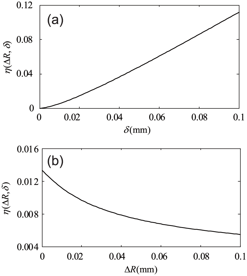
Parameter analysis of
The cftool command which is the curve fitting tool of MATLAB software was used to obtain the coefficients of equation (15). The coefficients are the fitting parameters which are decided by the material and geometric properties of a clearance joint. When the contact length is 15 mm, the fitting results and accuracy of parameters in equation (15) are listed in Table 1.
The fitting results and accuracy.
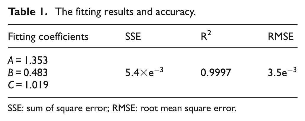
SSE: sum of square error; RMSE: root mean square error.
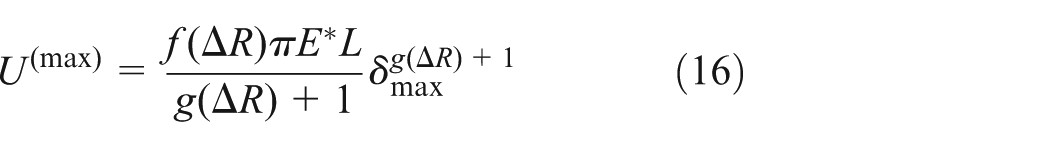
Combining equations (13)–(15), the maximum strain energy in the compression phase can be indicated as
Substituting equations (11) and (16) into equation (12), the equation of energy balance can be denoted as

The total momentum of system remains unchanged in the compression phase

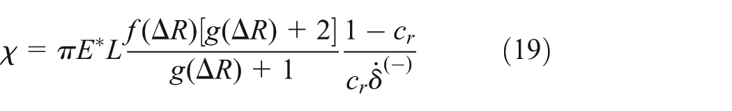
The functional relation of the hysteresis damping factor and the coefficient of restitution can be gained by combining equations (6), (10), (17), and (18)
Substituting equation (18) into equation (1), the CCF can be expressed as

The elastic force model was built by the static contact force model, which can describe the static contact process of the revolute joint more realistically upon comparison with the previous models. Furthermore, the damping force model was deduced by fitting the parameters of the elastic force model. The parameters of the proposed CCF model can be determined once the shape and materials of the revolute joint are given.
Analysis example
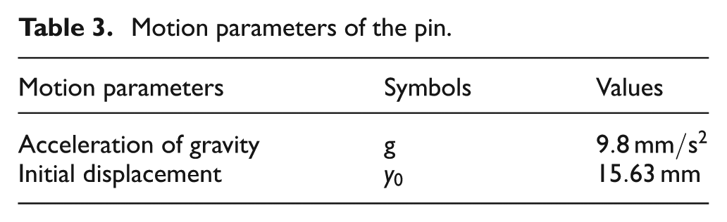
As shown in Figure 3, a free-fall pin comes into contact with a cylindrical groove at an initial height. Next, the parameters in the whole motion of pin, such as the displacement, indentation, contact velocity, and contact acceleration, can be obtained by the proposed CCF model. The materials of the pin and the cylindrical groove are all given as aluminum, and the geometric parameters and motion parameters are listed in Tables 2 and 3, respectively.

Free-fall pin contacts with a cylindrical groove.
Geometric parameters.

Motion parameters of the pin.
The pin and the cylindrical groove come into contact with each other once the displacement of the pin is up to 12.45 mm. In addition, the placement can be defined as the critical position of the contact phase and the separation phase. When the displacement of pin is higher than 12.45 mm, the pin and groove are in the state of separation. In the separation phase, the displacement of the pin shows an increasing tendency before the pin bounces to a maximum height.
The peaks of the displacement curve represent the local maximum of the height during the separation phase, as shown in Figure 4. A part of kinetic energy is dissipated by the damping of materials in the impact system; thus, the peaks gradually decrease with increasing time. In addition, the displacement of the pin approaches 12.45 mm.

Displacement curve of the pin.
The contact parameters, such as indentation, contact velocity, and contact acceleration, reflect the contact behavior of the contact–impact system to some extent. Next, the curves of the contact parameters are drawn in this part to analyze the contact phenomenon and validate the proposed CCF model. When the velocity of the pin approaches zero, the indentation approaches the maximum value, as shown in the curves of Figure 5. Because of the damping of the material in the system, the average contact force and contact acceleration in the compression phase are less than that in the recovery phase; thus, the time of compression phase is shorter than that of the recovery phase on the condition that the displacements of two phases are the same.

The curves of contact parameters.
The curves of the relationship between the contact force and the indentation with and without damping effect are drawn in Figure 6(a) to reveal how the damping affects the contact behavior during the first contact process of the pin and the cylinder groove. Considering the damping effect, the curve of the relation of contact force and indentation is labeled as curve 1, which is a nonlinear closed curve. Because of the existence of damping effect, the contact force in the compression phase is greater than that in the recovery phase. The curve of the relation of contact force and indentation without damping effect is labeled as curve 2, which divides curve 1 into two parts, the upper curve and the under curve. The upper curve and under curve describe the compression phase and the recovery phase in the contact process, respectively. Curve 1 describes the CCF, and curve 2 merely depicts the elastic force; thus, the damping force can be obtained by the difference of the contact forces of curve 1 and curve 2. The damping force is zero at the crossed point of the two curves; thus, the indentation achieves the maximum value at this time. During the first contact process, the total dissipated energy, which is equal to the work by the CCF, can also be obtained by calculating the surrounded area of curve 1.

Analysis of the contact force affected by parameters: (a) with and without damping, (b) various clearances, and (c) various initial relative velocities.
With different clearances, the dynamic characteristics of the pin contacting with the cylindrical groove are simulated in the example to analyze how the clearance affects the relationship between the CCF and the indentation. The proposed CCF model is more dissipative than the previous CCF models (except the Flores model) during the contact process of the revolute joint. Those previous models were established when small energy dissipation existed in the contact system, and the dissipated energy in the whole process was assumed to be approximately two times the dissipated energy in the restitution phase. However, the dissipated energy in the compression phase should be larger than the dissipated energy in the restitution phase when the coefficient of restitution is small. The proposed CCF model in the article has taken the dissipated energy in the compression and whole contact process into consideration; as a result, the model describes a situation with more dissipated energy in the contact process. As shown in Figure 6(b), the maximum indentation increases and the CCF decreases with the increasing clearance. Furthermore, the change rate of the CCF decreases gradually with the increase in indentation when the clearance is high. The maximum contact force increases with the increasing absolute value of the initial relative velocity, as shown in Figure 6(c).
To determine the effect degree of the external force, the changed displacement of the pin is obtained when various external forces are acting on the pin in the direction of gravity. Figure 7 reveals that the pin can rebound up to a certain height and then come into contact with the cylinder groove when the pin is under an external force of 250 N. Nevertheless, under high external forces that exceed 500 N, the pin contacts with the cylinder groove all the time and no longer has the ability to rebound up. Thus, it can be concluded that the dynamic characteristics of a planar revolute joint involving clearance are sensitive to external loads.
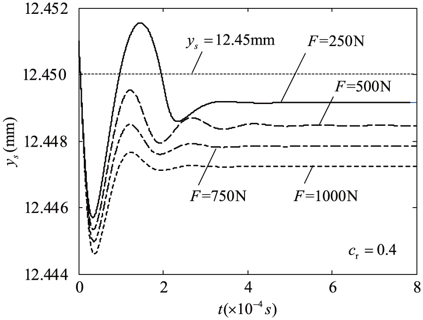
The displacement of pin with various external forces.
Dynamics analysis of planar revolute joint
Dynamical model
To further investigate the contact characteristics in a planar revolute joint, the dynamic model of a planar revolute joint was established based on the massless-link/spring–damper (MLSD) method and the modified Coulomb friction model. The MLSD method assumes that there is massless link whose length changes with the eccentric distance between kinematic pairs of a joint and a spring–damper between contact bodies.
The simplified physical model of a simple pendulum with a clearance joint is shown in Figure 8 to clearly describe the dynamic model. The pin of the revolute joint was fixed on the ground, and a link with the hole connects with the pin. The center of the pin was marked as point A, the center of the hole was marked as point
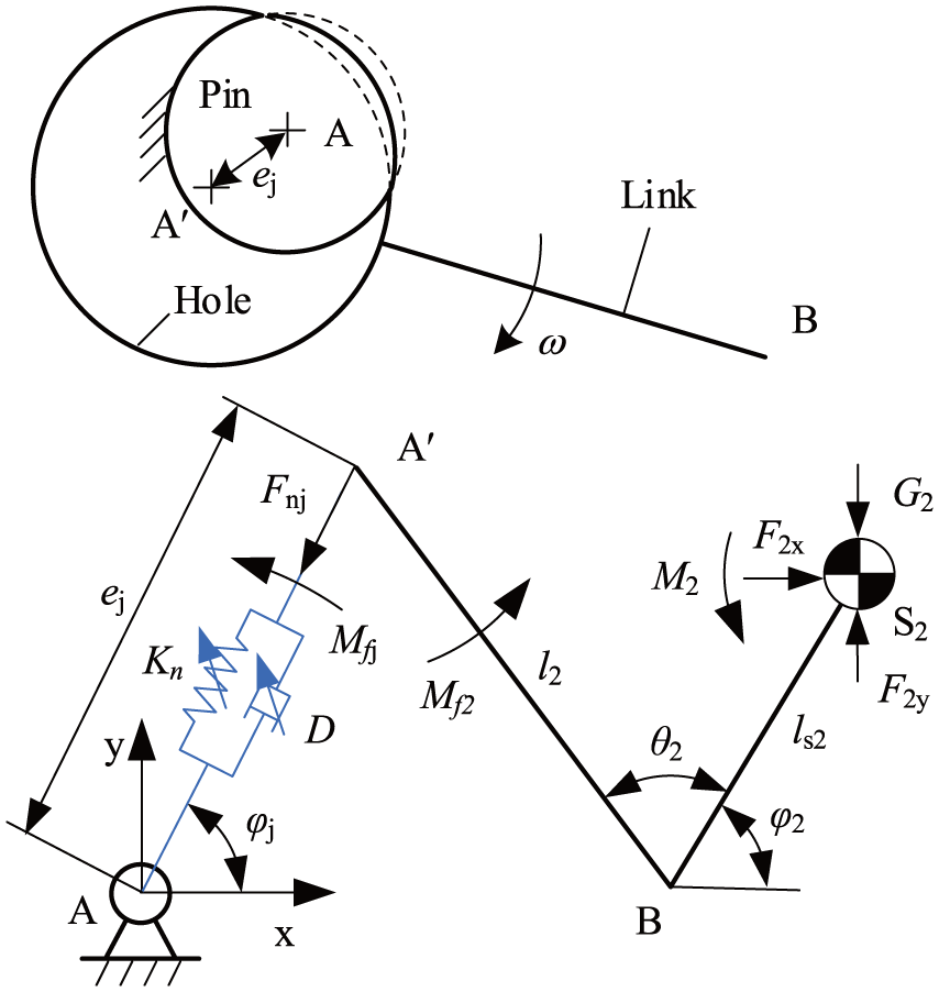
Dynamic model of a planar clearance joint.
The indentation represents the relative displacement between the pin and the hole of the planar revolute joint in the normal direction of initial contact points. In addition, the indentation can be obtained by the difference of the clearance and the eccentric distance in a planar revolute joint. The function of indentation is denoted as

Whether the pin has contacted with the hole of a joint can be determined according to the value of the indentation.42,43 The contact discriminant can be written as
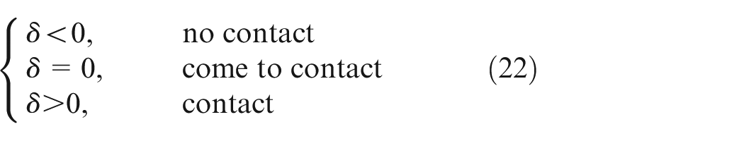
Based on the symbolic function, the contact discriminant can be expressed as

The normal contact force in the joint can further be represented as

The relative contact velocities can be gained by taking the derivative with respect to the indentation along the normal and tangential directions

In Coulomb’s friction model, it is assumed that the friction force is independent of the relative velocity of sliding in the tangential direction. The law relates the tangential and normal components of the reaction force at the contact point by introducing the friction coefficient. However, the friction forces should depend on many parameters, such as material properties, contact surfaces, and the relative velocity of sliding. 17 Considering the relationship of the friction force and the relative velocity of sliding, a modified Coulomb’s friction model was proposed43–45

where
It is necessary to calculate the relative sliding velocity in the tangential direction. According to equation (26), the relative sliding velocity can be obtained as follows

By the modified Coulomb model, the tangential friction force can be written as

The friction moment loading on massless link can be expressed as

The friction moment loading on link that is fixed with pin is expressed as

The generalized force of the clearance revolute joint can be expressed in matrix form, as follows

The spring–damper in the MLSD model can be treated as a massless and movable body, whose generalized coordinates are

where
The kinetic energy of the whole system is
where M is the generalized mass matrix of the joint system and is expressed as

and
The dynamics equations satisfy the following conditions

The constraint equation of the joint can be obtained by the geometrical dimensions and relative position of the component

The dynamics equation of the joint can be expressed as

where
where

Equation (34) can also take the following form

Analysis example
A simple pendulum with a clearance was used to analyze the dynamic characteristics of the planar revolute joint. The parameters of the simple pendulum are listed in Table 4. The location where the axes of hole coincide with that of pin in a joint is defined as the initial position; in this case, the pendulum rod fixed with the pin is released freely from the horizontal position.
Geometric parameters.

The trajectory of the center of the hole in the planar revolute joint with a clearance can be drawn as shown in Figure 9. The clearance circle is drawn with a dashed line, and the external curves of the clearance circle denote the trajectory where the pin contacts with the hole. Falling down freely from the height of a clearance size, the pin comes into contact with and separates from the hole of the joint many times, as shown in the oscillatory curves around point A of Figure 9. With a certain mass, the hole of the link contacts with the pin all the time after several times of contact and separation. In addition, the trajectory of the center of the hole passes through points B, C, D, and E.

The trajectory of the pin.
The maximum rotational angle of the link decreases from 90° to 87.64° as shown in Figure 10(a). The maximum contact force reaches 5510 N when the link falls down and impacts the hole of the joint, and then the contact force decreases after several instances of contact. When the rotational angle of link is zero, the normal contact force reaches the maximum value and the friction force comes to reach the maximum values at the same time according to Figure 10(a) and 10(b), respectively.

Movement and force curves of the rod: (a) movement curves of the rod and (b) force curves of the rod.
Experiment
An experimental test apparatus, as shown in Figure 11, was set up to confirm the validity of the proposed CCF model in this article. The equipment was driven by an EXLAR electric actuator, and the external load was provided by two pieces of plate springs. The relative location of two pieces of plate springs, which were made with 65Si2MnA, was adjusted to ensure that the moment was 2500 N m when the rotational angle comes to 18°. Two respective force sensors were used to determine the force of pushing rod and the external load. The HGLZ type of force sensor was chosen as force sensor 1, and the GLBLY type of force sensor was chosen as force sensor 2. The control surface, which was made of aluminum, was moved with a reciprocating motion by the pushing rod that was driven by a sine displacement with a period of 1 s. The displacement of pushing rod can be determined by a laser displacement sensor, and the rotational angle of control surface was acquired by an incremental encoder.

The experimental test equipment.
With a clearance of 0.045 mm, the planar revolute joint A connects the pushing rod and the control surface. The radius of the pin in joint A is 12.955 mm, and the material of the pin is no. 45 steel. The radius of hole is 13.001 mm. The clearances of joint O and joint B were all smaller than 0.005 mm.
The three-dimensional (3D) structure of the mechanism created by SOLIDWORKS software was imported into Adams software through a parasolid format file. The load applied by plate springs in the experiment was exported and then imported into the simulation model. The routine of the contact force model in the Adams software was replaced by the routine of the proposed CCF model to analyze the contact characteristics in the revolute joint by the proposed CCF model. In this article, the integrator format Si2 was chosen for the selected solver WSTIFF to verify the accuracy of the proposed CCF model and to investigate the dynamic characteristics of the clearance mechanism. The WSTIFF solver has the characteristics of variable step and variable coefficients in the Adams software, making it more robust and more accurate. The Si2 format can control the errors of the Lagrange multiplier and velocity by considering the velocity constrained equations. The dynamic simulation of the mechanisms with a clearance joint can be performed to obtain the force of pushing rod and the rotational angle.
Because of the clearance in the dynamic simulation model of the mechanism, the process of eliminating clearance will occur during the initial phase of motion. In the period, the collisions that exist in planar revolute joints will cause fluctuations of the simulated curves, as shown in Figure 12. The experimental force curve of the pushing rod starts to fluctuate with time, and the local maximum values of the formulation curve with clearance are closer to the experimental data compared to those of the formulation curve without clearance.
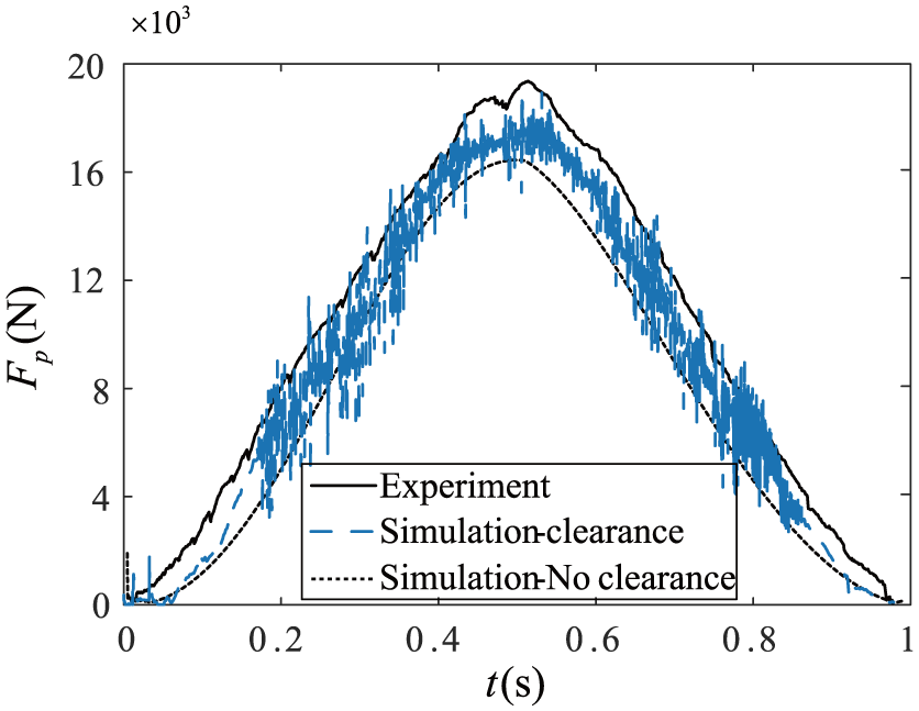
The forces of pushing rod.
At the initial phase, the control surface has a certain rotational angle, as shown in the formulation curve with clearance of Figure 13. When considering the clearance, the angle is found to be smaller than the angle without clearance at the same time. In addition, the experimental data of angle are close to the simulation data with clearance.

The rotational angle of control surface.
When a smooth sine displacement wave was adopted in the pushing rod of a mechanism without clearances, the force of the pushing rod should have no severe fluctuations. However, severe fluctuations appeared in the force curves of the pushing rod when the revolute joints involved clearances. The rotational angle of the control surface comes up to
To reduce the thermal effect on the system’s response, some measures were taken to reduce the friction force, such as improving the processing quality of the surface. Furthermore, the relative angles of the joints were not larger than
Conclusion
The proposed CCF model can avoid the two difficulties in modeling the CCF in a planar revolute joint with clearance. In this article, an appropriate static contact force model based on the elastic half-space theory and the geometric constraint is used as the elastic force portion of the CCF model for a planar revolute joint. In addition, the method of fitting the parameters of the static contact force model can reduce the difficulty of integrating the elastic force when the energy conservation method was used. By analyzing the proposed model, the following conclusions can be drawn: (1) the method of fitting parameters of the elastic force is a feasible approach to build the CCF model, (2) the proposed CCF model is able to analyze the contact characteristics of planar revolute joint involving a clearance according to the experimental results, and (3) the contact parameters, such as indentation and contact force, are sensitive to the clearance and the external force.
Footnotes
Academic Editor: Filippo Berto
Declaration of conflicting interests
The author(s) declared no potential conflicts of interest with respect to the research, authorship, and/or publication of this article.
Funding
The author(s) disclosed receipt of the following financial support for the research, authorship, and/or publication of this article: This work was supported by National Natural Science Foundation of China (grant no. 61403106) and Program of Introducing Talents of Discipline to Universities (B07018).