
Abstract
A heat sink with convective boiling in micro- or mini-channels is with great potential to meet the requirement of the high heat dissipation of the electronic devices. This study investigates the flow boiling of HFE-7100, having a suitable boiling temperature at atmospheric pressure and dielectric property, in the minichannel heat sink with the modified surface (namely, the saw-tooth structure). The effect of the system pressure on the boiling characteristics was also studied. The results reveal that the critical heat flux can be significantly improved by introducing the saw-tooth structures on the channel surface or boosting the system pressure as well as by increasing the mass flux. Compared to the non-modified channel, the enhancements of the critical heat flux for the parallel and counter saw-tooth channels are 44% and 36%, respectively, at the small mass flux. The boiling visualization further indicates that the minichannels with the saw-tooth structures interrupt the boundary layer and restrain the coalescence of the bubble, which may be the reason for the critical heat flux enhancement. Moreover, the degree of the critical heat flux enhancement, contributed by the saw-tooth modification of the channel, decreases with an increase in the mass flux.
Introduction
Due to great advancement in the semiconductor technology, the size of a chip is dramatically reduced and the heat dissipation of the electronic devices significantly increased and become a critical issue. A heat sink with convective boiling in micro- or mini-channels is with great potential to meet this thermal transport challenge. An environmental-friendly refrigerant HFE-7100 is one of the promising candidates for such a heat sink due to its suitable boiling temperature at atmospheric pressure and dielectric property. 1 In addition, using HFE-7100 as the working fluid under a condition of a higher reduced pressure may suppress the flow instability in microchannels. 2 Many studies concerning the boiling two-phase flow of HFE-7100 in a microchannel heat sink have been reported in recent years. For example, Yang et al. 3 investigated the effect of the hydraulic diameter of the microchannel on the boiling heat transfer and flow pattern evolution of HFE-7100 in a microchannel heat sink. They found that at given heat and mass fluxes, the heat transfer performance in the small channel with a hydraulic diameter of 480 µm was much higher than that in the large channel with a hydraulic diameter of 790 µm. In addition, the heat transfer coefficients for both sizes of channel were not influenced by the mass flux. Their flow visualization further demonstrated that the dominant flow pattern for the small channel was churn/annular flow due to a confinement space, resulting in a negligible effect of heat flux on the flow pattern; however, for the large channel, the flow pattern generally evolved from bubbly, elongated bubble, slug, and finally churn/annular flow as the heat flux was increased. In addition, for the small mass flux, the flow reversal was present in the small channel but was absent in the large one, resulting in a somewhat reduction of the heat transfer performance in the small channel. They also reported that the classic Cooper correlation could well predict the results in the large channel but was not as well in the small one.
Hsu et al. 4 conducted an experimental study to investigate the effect of inclination angle (i.e. −90° (vertical, downward flow), −45° (downward flow), 0° (horizontal), 45° (upward flow), and 90° (vertical, upward flow)) on the boiling heat transfer of HFE-7100 in a microchannel heat sink with a hydraulic diameter of 440 µm. Their results illustrated that the heat transfer coefficient for the upward flow was generally higher than those of downward flow. Another similar study by Wang et al. 5 reported that such an increase in the heat transfer coefficient for the upward flow arrangement was mainly due to the rise of slug bubble velocity (buoyancy effect). Hsu et al. 4 also demonstrated that for a small heat flux, the heat transfer coefficient increased as the vapor quality increased until approaching quality of 0.6, indicating heat transfer is dominated by the convective boiling. However, for a higher heat flux, the heat transfer coefficient for all flow arrangements was not influenced by the quality (<0.6), which suggested nucleate boiling being the controlling mechanism. In addition, for all their studied cases, the maximum heat transfer coefficient occurred at a quality of about 0.6 and, then, dropped dramatically when the quality was further increased, which was believed to be caused by the partially dry out occurrence.
Fu et al. 6 employed HFE-7100 as a working fluid to study the effect of aspect ratio of a microchannel on the flow boiling heat transfer. The microchannels with the aspect ratio of 0.83, 0.99, 1.65, 2.47, 4.23, and 6.06 were tested, of which the hydraulic diameter was designed to be the same of 1.12 mm. Their results demonstrated that at a given wall temperature, significant differences were observed among the microchannels with different aspect ratios in the two-phase boiling region but were not present in the single-phase convection region; and the critical heat flux (CHF) reached the highest value at the aspect ratio of 0.99 due to copious existence of the liquid film around the corner. They also proposed an empirical CHF correlation including the aspect ratio parameter during the flow boiling in the microchannel.
In addition to the flow boiling in the microchannel heat sink, some other applications of HFE-7100 have been widely studied, such as using HFE-7100 as the working fluid to study the heat transfer characteristics during the jet cooling of the surface 7 or the boiling heat transfer and pressure drops in the plate heat exchangers. 8 HFE-7100 was also employed to investigate the CHF and post-CHF characteristics during the falling jets on the surface with localized electrostatic fields 9 or the heat transfer enhancement of the pool boiling on the nanoparticle-coated surface. 10
In recent years, many approaches have been reported to improve the boiling heat transfer in the microchannel. For example, Yang et al. 11 developed the microchannel with nanowire-coated surfaces to enhance the flow boiling heat transfer of HFE-7000. They demonstrated that compared to the non-modified microchannel, the heat transfer coefficient was substantially enhanced by 344% in the nanowire-coated microchannel. Deng et al. 12 developed the reentrant porous microchannels to study the flow boiling characteristics of ethanol. The experimental results demonstrated that the wall superheat for the onset nucleate boiling was 0.6°C–1.8°C, indicating that such porous microchannels enhance the bubble nucleation and increase the nucleation sites during the flow boiling. Law and Lee 13 investigated the flow boiling of FC-72 in the microchannel heat sink with different designs of the micro-fin. Their results showed that the liquid film disruption by the downstream oblique channels was beneficial for the convective boiling heat transfer in the oblique-finned microchannels. In addition, both heat transfer coefficient and CHF in the oblique-finned microchannels were much higher than that in the straight-finned microchannels, which was attributed to the better system stability during the flow boiling. Buchling and Kandlikar 14 proposed the open microchannel with tapered manifolds to study the flow boiling of ethanol. They reported that the enhancement of the heat transfer performance was over 340% compared to the previous results. Such tapered design is similar to the concept of the diverging microchannel, 15 which can significantly reduce the system instability and improve the heat transfer performance during the flow boiling. The detailed mechanisms of different methods for the flow boiling enhancement are available in some review articles, such as Kandlikar, 16 Wu and Sundén, 17 and Kim et al. 18
This study investigates the flow boiling heat transfer of HFE-7100 in the minichannel heat sink with saw-tooth structures. The flow boiling in the parallel and counter saw-tooth arrangements as well as in the non-modified surface was conducted. The effect of the system pressure on the boiling characteristics was also performed. Moreover, the boiling visualization and the CHF were further explored.
Experimental details
Experimental setup
Figure 1 illustrates the experimental setup, consisting of a high-performance liquid chromatography (HPLC) pump (Dionex, model: HPG-3200P), a test section coupled with a heating module, a low-temperature cooling tank, a storage tank of the working fluid (HFE-7100) connected with a high-pressure helium cylinder, pressure transducers (Huba, model: 691), a data acquisition system (YOKOGAWA, model: MX100), a flow visualization system, and a computer. Before the experiments, degassing of HFE-7100 was conducted by an ultrasonic oscillator under the vacuum condition for about 3 h. In the present experiments, the HPLC pump drove the liquid HFE-7100 at a given flow rate through the minichannel heat sink, where HFE-7100 is heated into two-phase flow. The two-phase fluid exhausts from the heat sink were fully condensed through the low-temperature water bath and then back to the storage tank. In addition, the high-pressure helium cylinder was employed to build a higher inlet pressure of the system. The system pressures of 1 atm (i.e. local atmospheric pressure condition) and 3.5 bar were tested during the experiments. Two T-type thermocouples were installed at the inlet/outlet of the heat sink to measure the fluid temperature. Three T-type thermocouples were embedded in the heating module (the distance to the bottom surface of the channels is 4 mm), and the mean value of these three temperatures is assumed to be the wall temperature of the channel. The pressure transducers were located at the inlet and outlet of the heat sink to measure the system pressure and the pressure drop during the flow boiling. The data acquisition system, connected to the computer, recorded signals from the thermocouples and pressure transducers with a sampling rate of 20 Hz. In addition, the present flow visualization system consists of a high-speed digital camera (IDT, model: MotionPro X4 Plus) mounted with a microlens (OPTEM, model: Zoom 125C) and fiber optic illuminator for steady-state visualization and recording. The typical frame rate and exposure time were set at 1000−5000 frames/s and 330 µs, respectively. In the present experiments, the time required to approach the steady state of the system was about 40 min.
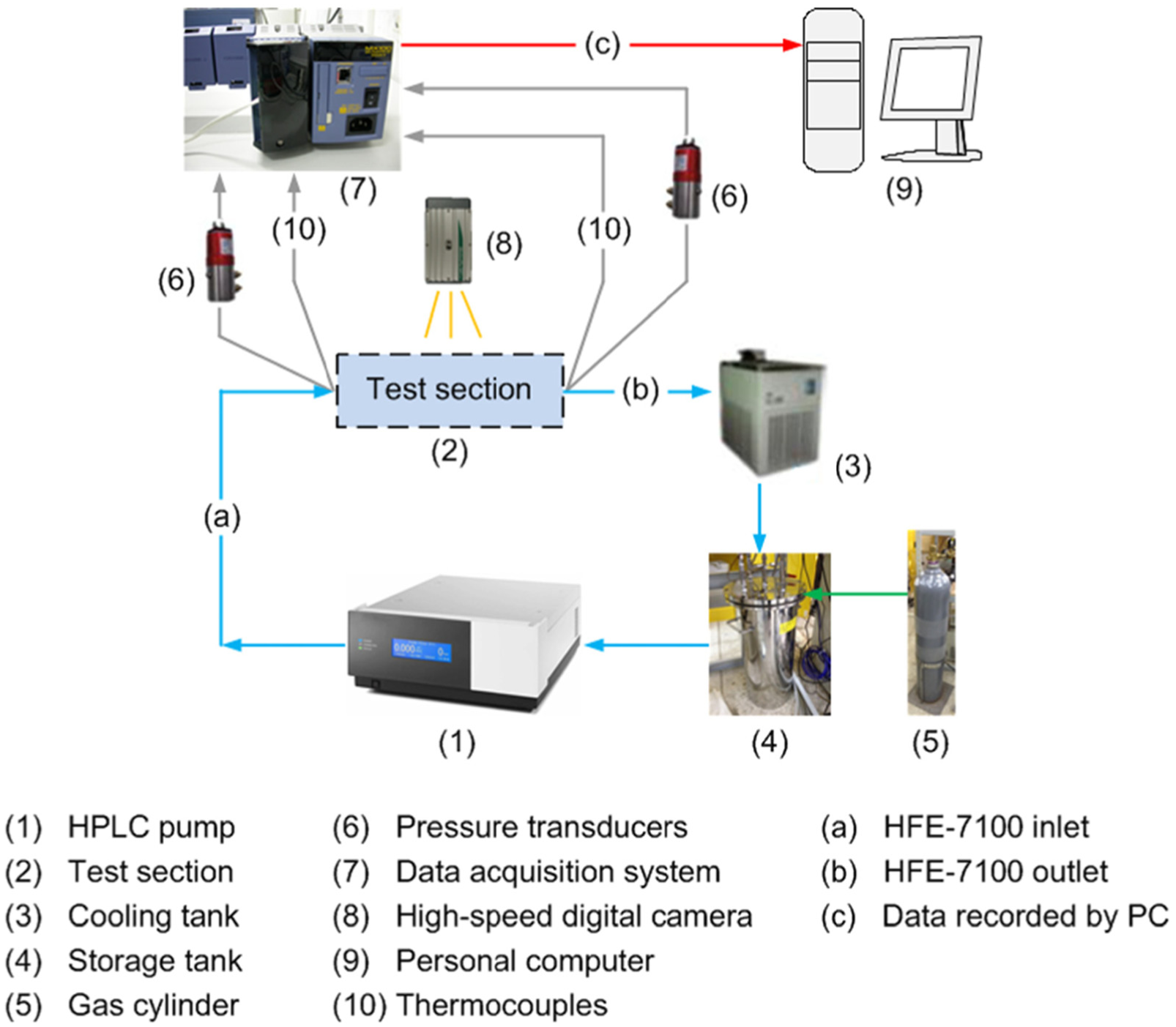
Experimental setup.
Test section and experimental procedures
The test section, as shown in Figure 2, was assembled with the minichannel heat sink and heating module. 19 The heat sink with four minichannels was manufactured on a copper block with dimensions of 90 mm (length) × 5 mm (width) × 30 mm (height). The depth and width of the flowing channel were 2 and 0.5 mm, respectively, resulting in a hydraulic diameter of 0.8 mm. The tip angle and tip height of the saw-tooth structures were 45° and 0.5 mm, respectively, as depicted in Figure 3. The saw-tooth topology on the bottom surface of the channel was manufactured by wire-cut electrical discharge machining. Three kinds of surface structures, that is, plain (without the modified surface), parallel, and counter saw-tooth structures were studied. The heating module with dimensions of 110 mm (length) × 30 mm (width) × 14 mm (height) was a copper block, which was embedded with two controllable cartridge heaters. In addition, the test section was integrated with an insulated module to minimize heat loss on the top of the channel and mounted with quartz glass to enable flow visualization.

Test section assembly.
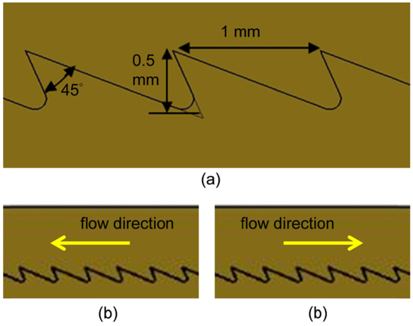
Tip configuration and flow arrangements: (a) tip configuration, (b) parallel saw-tooth structure, and (c) counter saw-tooth structure.
The experimental procedures for this study were described as follows: (a) checking the experimental loop was leak free; (b) setting up the HPLC at a given flow rate and turning the HPLC pump on; (c) setting and turning on the heating module at a given power; (d) recording the temperature, pressure, and the two-phase flow patterns when the steady state was reached; and (e) changing the power level and repeating steps (d) and (e).
Data reduction
The data reduction of the heat transfer during the flow boiling in the minichannel was based on the procedures developed by Lee et al. 20 Energy balance requires that the total heat input (Qtot) from the heating module is equal to the sum of the thermal energy transferred to the working fluid (Qf) in the heat sink and the heat loss (Qloss)

In the single-phase flow region, the heat absorbed by the working fluid in the heat sink can be calculated from the temperature difference of the fluid at the outlet and inlet

where m is the mass flow rate of the working fluid, Cp is the specific heat of the working fluid, and Tout and Tin are the fluid temperature at the outlet and inlet of the heat sink, respectively. Therefore, the heat loss can be obtained from equations (1) and (2). In this study, the heat loss in the single-phase flow region increases linearly with an increase in the temperature difference between the system (using the mean wall temperature of the heat sink, Tsys) and ambient temperature (Ta), as demonstrated in an example of Figure 4. Such a linear relationship between the heat loss and (Tsys − Ta) should be still true even after boiling takes place in the minichannel. Thus, such a linear relationship was further extrapolated to those temperatures when the boiling of the fluid occurred in the heat sink and, therefore, the heat transferred to the fluid can be calculated by equation (1) with Qloss obtained. The heat flux (q″) can be obtained by dividing the heat absorbed by the fluid with the base area of the heat sink and then the corresponding two-phase heat transfer coefficient (htp) is calculated by the following basic equation

where ΔTsat is the wall superheat (i.e. ΔTsat = Tw − Tsat), Tsat is the saturated temperature of the working fluid corresponding to the system pressure, and Tw is the wall temperature.
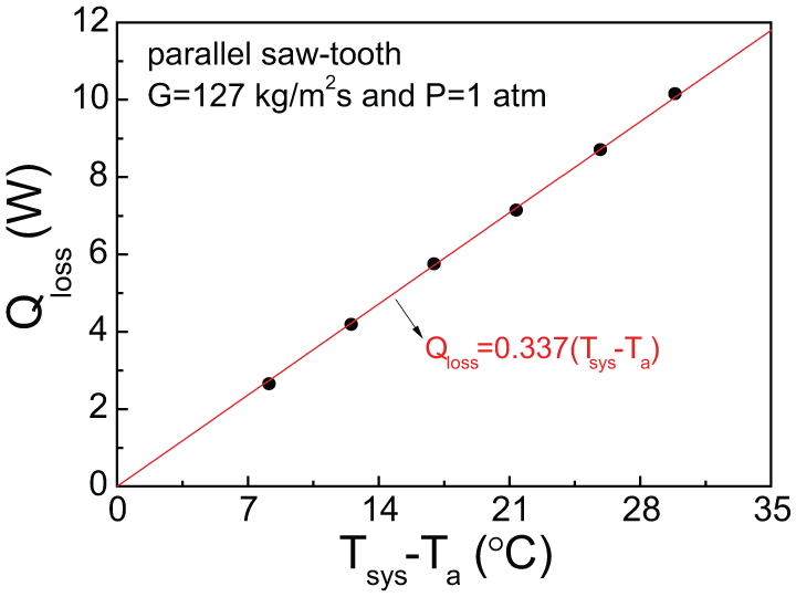
Heat loss as a function of the temperature difference between the system temperature (Tsys) and ambient temperature (Ta) under the single-phase flow condition.
Uncertainty analysis
In the present experiments, the uncertainty for the volume flow rate of the working fluid (also for the mass flux at a given cross-sectional area of the channel and liquid density) through the minichannel heat sink was ±0.27%. The uncertainty in the temperature measurement (for Tout and Tin) was ±0.2°C for the T-type thermocouple. The uncertainty in the pressure transducer measurement was ±0.5%. The methodology of uncertainty analysis proposed by Moffat 21 was further employed to calculate the uncertainty of an experimental result obtained from measurements with above known uncertainties. In this analysis, it is assumed that the uncertainties in the thermophysical properties of the working fluid (such as Cp, T sat , and thermal conductivity), the geometric size of the flow channel, and the heating power are ignored. The maximum uncertainty of the heating power is estimated, based on the uncertainties of the current and voltage, to be 0.1%, for the lowest heating power of the two-phase flow condition, which is negligibly small compared to that of the heat loss. As an example of error analysis, the uncertainty for the heat flux in the single-phase flow region comes from the uncertainties of m, T out , and Tin, as indicated in equation (2). The maximum uncertainty (i.e. 25.7%) of the heat flux in the single-phase flow region appears at the conditions of Tout = 29.1°C, Tin = 28.0°C, q″ = 3.29 kW/m2, and G = 285 kg/m2 s, of which the calculation is detailed as: {(0.27%)2 + [0.2/(29.1 − 28.0) × 100%]2 + [0.2/(29.1 − 28.0) × 100%]2}1/2 = 25.7%. This is a case for the minimum difference in the fluid temperature between the channel inlet and outlet while heating. The uncertainties for other variables can be estimated in the same way and are summarized below: Tw, ±0.35°C; Qloss in the two-phase flow region, ±0.52% to ±1.19%; q″ in the single-phase flow region, ±1.37% to ±25.7%; q″ in the two-phase flow region, ±0.08% to ±0.71%; and htp, ±0.79% to ±65.0%. In the present experiments, the uncertainty of the heat flux decreases dramatically with an increase in the heat flux, especially in the single-phase flow region.
Results and discussion
Figure 5 shows the heat flux as a function of the wall superheat, based on the bottom wall surface of the channel, in the three types of the minichannel heat sink at the mass flux (G) of 127 kg/m2 s and the system pressure (P) of 1 atm. In the present experiments, the pressure drop through the minichannel heat sink is negligibly small (<1 kPa) for both single- and two-phase flow regions. Thus, the saturated temperatures of the working fluid (HFE-7100) are 61°C and 104°C, respectively, corresponding to P = 1 atm and 3.5 bar. The critical pressure for HFE-7100 is 22.3 bar, and 3.5 bar corresponding to a reduced pressure of 0.157. This figure illustrates that for the single-phase convection region (ΔTsat < 0°C), the heat flux increases almost linearly from 1.7 to 27.9 kW/m2 as the wall superheat increases from −30°C to 0°C, and followed by a rapid increase in the heat flux in the boiling two-phase region until approaching the CHF condition. The wall superheat for the CHF occurrence is about 15°C–20°C under this operation condition. In addition, the figure indicates that the boiling curves for the present minichannel heat sinks with three different surface structures are quite similar in the single-phase convection region as well as in the boiling two-phase region with a small wall superheat (ΔTsat < 5°C). By contrast, those three boiling curves begin departing to each other as the wall superheat continuously increases and reaches its CHF condition. This figure further demonstrates that the highest CHF is obtained in the heat sink with the parallel saw-tooth structures, whereas the lowest CHF is present in the plain surface channel. However, the difference in the CHF for the parallel and counter channels is insignificant. The CHFs for the plain, parallel, and counter saw-tooth channels are 117, 168, and 159 kW/m2, respectively. Compared to the plain channel, the enhancements of the CHF for the parallel and counter channels are 44% and 36%, respectively. The results reveal that the CHF can be significantly improved by introducing the saw-tooth structures on the channel surface.

Boiling curves in the three types of the minichannel heat sink at G = 127 kg/m2 s and P = 1 atm.
The two-phase heat transfer coefficient can be readily obtained from the boiling curve. For example, corresponding to the case presented in Figure 5, Figure 6 shows two-phase heat transfer coefficients in the three types of the minichannel heat sink at G = 127 kg/m2 s and P = 1 atm. This figure clearly indicates that the two-phase heat transfer coefficient reaches its maximum value in the beginning while entering the boiling region (i.e. with a very small ΔTsat) and then decreases rapidly as the wall superheat increases from 2.5°C to 7.5°C, and finally approaches to the value of about 10 kW/m2 K until the CHF condition is reached. The present results of the two-phase heat transfer coefficient are very close to our previous report. 6
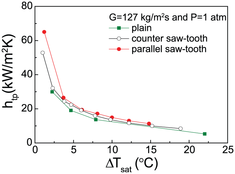
Two-phase heat transfer coefficients in the three types of the minichannel heat sink at G = 127 kg/m2 s and P = 1 atm.
Figure 7 presents the boiling curves at a higher mass flux (G = 285 kg/m2 s) and P = 1 atm. For the single-phase convection region, the boiling curves for different channels are also similar, in which the heat flux increases from 3.3 to 58.6 kW/m2 as the wall superheat increases from −30°C to 0°C. Those heat fluxes are about two times of that at the mass flux of 127 kg/m2 s. For the boiling two-phase region, the boiling curves for the channels with the saw-tooth structures are almost the same but below the boiling curve for the channel with plain surface for the wall superheat less than 20°C. After the wall superheat exceeds 20°C, these two boiling curves begin to deviate, where the early occurrence of the CHF is observed in the channel with the parallel saw-tooth structure. The CHFs for the parallel and counter saw-tooth channels are 279 and 303 kW/m2, respectively, which is much higher than that at the mass flux of 127 kg/m2 s. The CHF for the plain channel (i.e. 257 kW/m2) is somewhat lower than that of the parallel saw-tooth channel. Figure 7 also demonstrates that the CHF occurs at the wall superheat of about 30°C–40°C for this relatively high mass flux, which is much higher than the results under the small mass flux and the same system pressure. The CHF enhancements for the parallel and counter channels are only 9% and 18%, respectively.

Boiling curves in the three types of the minichannel heat sink at G = 285 kg/m2 s and P = 1 atm.
For the plain channel, the better performance of the heat transfer in the beginning of the boiling two-phase region, as shown in Figure 7, is mainly caused by the different flow patterns observed in the plain channel. For this study, before the CHF occurrence, the two-phase flow pattern evolves from the bubbly flow, slug flow, churn-annular flow, to annular flow with an increase in the heat flux at a given mass flux. Figure 8 shows the visualization of the flow boiling in the minichannel heat sink with different surface structures under the same mass flux of 285 kg/m2 s and approximately the same heat flux. This figure illustrates that in the upstream of the channel, the bubbly flow is observed for all three different channels; in the middle of the channel, the annular flow is present in the plan channel whereas the slug flow is dominant in both parallel and counter saw-tooth channels; and in the downstream of the channel, the annular flow with partial dry out is frequently occurred in the plain channel whereas the churn-annular flow is present in the other channels. In general, the heat transfer performance of the annular flow during the flow boiling is considered to be better than that of the slug flow. However, the early appearance of the annular flow in the plain channel also leads to the early dry out of the liquid film and the occurrence of the CHF, compared to the other channels. The flow visualization clearly demonstrates that the minichannels with the saw-tooth structures interrupt the boundary layer and restrain the coalescence of the bubble, and therefore delay the formation of slug flow and subsequently the annular flow. The CHF enhancement thus was achieved in the channels with saw-tooth structures.
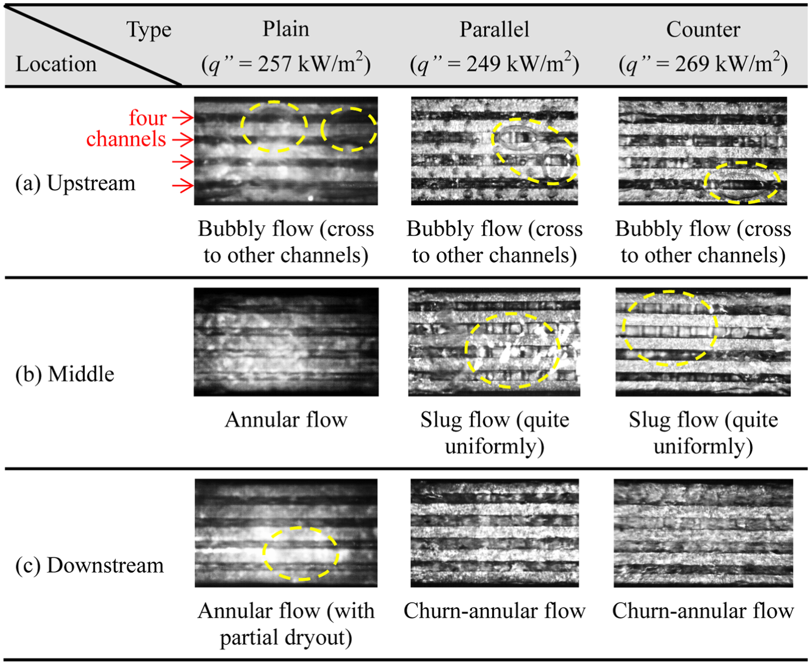
Visualization of the flow boiling in the minichannel heat sinks under G = 285 kg/m2 s, P = 1 atm, and the similar heat flux.
In addition, due to the incomplete seal between the quartz glass and the minichannel heat sink, the vapor bubble and the liquid carried with frequently crosses to other channels when it grows to a larger one. Such a phenomenon may effectively reduce the system instability during the flow boiling in the minichannel and may also increase the surface area for the heat transfer process. However, the surface temperature at the top of the separation island, like a fin tip, between two neighboring channels should be significantly lower than that of the bottom wall. Therefore, the heat transfer from the separation island top should be small. Moreover, such a possible effect of surface area increase for three studied heat sinks on the heat transfer behaviors can be considered nearly the same due to an identical manufacturing and sealing process of the heat sinks. It is also interesting to find that the slug bubbles in the parallel and counter saw-tooth channels distribute quite uniformly, as depicted in Figure 8, which suggests the good design of the present test section.
The saw-tooth structure not only can interrupt the boundary layer as indicated earlier but also influence bubble nucleation. The possible micro-vortex flow structure in the region between two neighboring teeth, as speculated and illustrated in Figure 9, may have different effects on bubble nucleation for different flow directions. For the parallel case under a low mass flux, the micro-vortex flow in the region is expected to be weak or even stagnant in the region under the tooth enhancing bubble nucleation there. However, the micro-vortex flow in the region should be much stronger for the counter flow case as the bulk flow will tend to drive the bulk liquid that is relatively cool toward the region under the tooth and bubble nucleation there will be more difficult. Indeed, this is the case as illustrated for G = 127 kg/m2 s in Figure 10, which clearly demonstrates more active bubble nucleation and coalescence in the region near the channel inlet for the parallel flow case. This explains why, for G = 127 kg/m2 s, the parallel saw-tooth case presents a higher heat flux at a given wall superheat for a heat flux greater than 120 kW/m2 and somewhat a higher CHF, as shown in Figure 5.
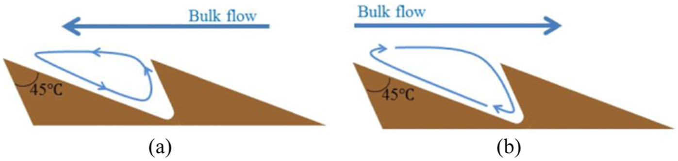
Micro-vortex flow speculated in the region between two neighboring teeth: (a) parallel saw-tooth flow and (b) counter saw-tooth flow.

Bubble nucleation in the region near channel inlet for G = 127 kg/m2 s: (a) parallel saw-tooth, q″ = 149 kW/m2 and (b) counter saw-tooth, q″ = 141 kW/m2.
Under the condition with a higher mass flux, the micro-vortex flow between two neighboring teeth may become stronger for both flow directions, and there is no significant difference on bubble nucleation near the channel inlet. Consequently, both flow directions demonstrate nearly the same boiling curve. The CHF in this study is induced by the dry out of liquid film, as annular flow prevails in the region near the channel outlet under the condition of high heat fluxes. As indicated earlier, the counter saw-tooth structure tends to drive the liquid toward the region under the teeth; the CHF is, therefore, further enhanced for the case with counter saw-tooth structure under a high mass flow rate condition, as shown in Figure 7 for G = 285 kg/m2 s.
Figure 11 shows the boiling curves for the different channels at G = 190 kg/m2 s and the higher system pressure (P = 3.5 bar). This figure demonstrates that the boiling curves for the studied channels in the single-phase convection region and in the boiling two-phase region with the small wall superheat (ΔTsat < 10°C) have no obvious difference. The plain channel presents somewhat poorer single-phase heat transfer and somewhat better heat transfer after the boiling incipience compared with other two channels. However, as the wall superheat exceeds 10°C and approaching the CHF condition, the boiling curves significantly differ. The CHF for the plain, parallel, and counter saw-tooth channels are 229, 281, and 306 kW/m2, respectively, in which the wall superheat is about 30°C–40°C. Such CHF level is close to the results of G = 285 kg/m2 s at P = 1 atm, indicating that the heat transfer performance can be improved as the system pressure boosts. In addition, the CHF enhancements for the parallel and counter saw-tooth channels are 23% and 34%, respectively. The present results illustrate that the counter saw-tooth channel yields the higher CHF enhancements at the higher mass fluxes whereas the parallel one has a better CHF improvement at the small mass flux. In conclusion, the results demonstrate that the degree of the CHF enhancement contributed by the saw-tooth modification of the channel decreases with an increase in the mass flux, as shown in Figure 12.

Boiling curves in the three types of the minichannel heat sink at G = 190 kg/m2 s and P = 3.5 bar.

CHF enhancement, compared to the plain channel, for the channels with the saw-tooth structures.
Conclusion
This study investigates the flow boiling of HFE-7100 in the minichannel heat sink with saw-tooth structures. The test section is made of the copper block, in which four minichannels with a hydraulic diameter of 0.8 mm are fabricated. Experiments under system pressures of 1 atm and 3.5 bar were conducted. The present results reveal that the CHF can be significantly improved by introducing the saw-tooth structures on the channel surface or boosting the system pressure as well as by increasing the mass flux. The results also demonstrate that the boiling curves for the parallel and counter saw-tooth channels are very similar except for the regions near the CHF. Compared to the non-modified channel, the enhancements of the CHF for the parallel and counter saw-tooth channels are 44% and 36%, respectively, at the small mass flux. The boiling visualization further indicates that the minichannels with the saw-tooth structures interrupt the boundary layer and restrain the coalescence of the bubble, which may be the reason for the CHF enhancement. Moreover, the degree of the CHF enhancement, contributed by the saw-tooth modification of the channel, decreases with an increase in the mass flux.
Footnotes
Acknowledgements
This work is an enhanced version of our conference paper presented at the ASME 5th international conference on micro/nanoscale heat and mass transfer (3–6 January 2016, Biopolis, Singapore).
Academic Editor: Jinjia Wei
Declaration of conflicting interests
The author(s) declared no potential conflicts of interest with respect to the research, authorship, and/or publication of this article.
Funding
The author(s) disclosed receipt of the following financial support for the research, authorship, and/or publication of this article: This work was financially supported by a Program from Plan to Develop World-Class Universities and Top-Notch Research Centers (grant number 104N2707E1) and by Ministry of Science and Technology, Taiwan (grant number 103-2221-E-007-112-MY3).