
Abstract
Unidirectional fiber-reinforced composites of “plain” carbon fiber–reinforced polymer laminates and carbon nanofibers modified carbon fiber–reinforced polymer laminates were prepared based on the manufacture of the epoxy resin modified with various contents of carbon nanofibers. The carbon nanofibers–modified epoxy matrix and carbon fiber–reinforced polymer laminates specimens were subject to constant amplitude cyclic tensile loading, quasi-static tension loading, and incremental cyclic tension loading while the values of their electrical resistance were monitored through electrical resistance technique. Resistance-change curves of carbon nanofibers/carbon fiber–reinforced polymer laminates indicated the changes in conductive percolation networks formed by carbon fibers or carbon nanofibers. These changes can identify the complex damage modes and the loss of mechanical integrity in laminates. The changes in resistance of specimens showed a nearly linear correlation with the strain, so the damage process of the carbon fiber–reinforced polymer laminates can be self-sensed according to the resistance-change curves. In addition, uniformly dispersed carbon nanofibers formed a network that spans the whole insulation area, which improved their self-sensing property of strain sensitivity without compromising the mechanical properties of the carbon fiber–reinforced polymer laminates. This technology can achieve the quantitative strain and damage self-sensing properties of nano-reinforced composites without any additional sensor, and it is bound to be a promising method for in situ health monitoring.
Keywords
Introduction
The research and development of smart materials have been pushed to the higher level due to the rapid development of advanced composite materials. The aim of studying smart materials is to provide the abilities for self-sensing and feedback in the process of using, so as to achieve multi-functionality. Fiber-reinforced polymer (FRP) is one of the hottest smart materials. Because of its excellent mechanical and electrical properties such as high strength and conductivity, low density, carbon fiber–reinforced polymer (CFRP) has become the most widely used composite material on the structure. At present, the researches about CFRP have involved in various fields of building structure, such as the concrete beams reinforcement, 1 roof reinforcement, 2 and manufacture of composite drive shaft. 3 However, micro-cracking and delamination may occur in CFRP materials, which are not be visible to the naked eye but reduce the in-plane strength and stiffness of composites during service.4,5 Therefore, the real-time damage identification plays a key role in CFRP materials function and structural safety.
The health monitoring sensors should meet the requirements such as small weight and size and high sensitivity in long service life. 6 Several nondestructive testing methods such as X-ray, 7 optical fiber, 8 and acoustic emission sensors have been used for health monitoring of FRP. But almost all of the traditional health monitors need a prediction for damage area in advance, and some of them need additional sensors inside FRP, which will introduce defects into materials. Therefore, monitoring the resistance changes has become the best way to realize continuous online monitoring for CFRP; thus, the function of self-sensing can be achieved. The uniqueness of this view is supported by the capability of real-time self-sensing without any additional sensors.
CFRP is made of high-conductive carbon fibers (CFs) interleaving as bunches or warp/weft shapes in the insulating matrix. Although the epoxy is almost insulating, the conductive paths can be formed relying on the contact between CFs. The contact points broke up with the appearance of strain or damage, which leading to changes in resistance of materials. And it is noteworthy that CFs shows a linear increase in resistance about 0.1% strain. 9 The earliest study on getting the damage information of material internal structure through monitoring the resistance of CF was completed by Schulte and Baron. 10 Further researches11–13 confirmed that the stress state of composites can be self-sensed through measuring the electrical resistance changes of CFs network simply and practically, and the CFs can act as inherent sensors of their own damage. Therefore, we can make a point that monitoring the strain and damage of coupon through the electrical resistance technique (ERT) is a promising self-monitoring technique. However, for the woven CFRPs, the resistivity in the thickness direction of CFRP laminate is higher than the in-plane resistivity about 1000 times, and the electrical properties of CFRP show anisotropy. 14 The self-sensing of matrix cannot be achieved relying solely on measuring the change in conductivity network of CFs because there is no conductive medium in the insulating matrix. In addition, significant plastic deformation is produced between the CFs and matrix 15 once the damage occurs due to their poor interfacial adhesion. Meanwhile, the CFRP laminate is extremely susceptible to generate micro-cracks which will propagate along the laminar interfaces, so it is necessary to improve the performance in their thickness direction. However, existing reinforcement method such as z-pin 16 will destroy the integrity of the materials and reduce their mechanical properties.
Introducing the nano-scaled fillers, such as carbon nanotubes (CNTs), carbon nanofibers (CNFs) into the CFRP offered a new solution toward this problem. Several researchers have worked on the hybrid multiscale composites by incorporating CNTs or CNFs networks within polymer matrix. The addition of nano-enhanced phase strengthened the combining capacity between the CFRP layers, and it is easy to understand that CNFs or CNTs will dissipate additional energy 17 when they are pulled out from the matrix if the matrix materials get injured. Besides, the micro-cracks were bridged by reinforcements so as to slow down the crack growth. 18 As a conclusion, the interlaminar shear and impact resistance of polymer nano-composites will be bound to increase.13,19–23 The presence of conductive particles in matrix improved the electrical conductivity of the material without loss of their mechanical properties. 24 Meanwhile, the three-dimensional electrically conductive networks mediated the electrical anisotropy of CFRP, and the conductivity of materials tends to be electrically isotropic 25 as a result of the significant increase in conductivity in thickness direction. 26 With the conductive mechanism in matrix of CFRP, mechanical stresses/strain, as well as destruction, can be detected via the in-situ electrical resistance measurements. Besides, the higher sensitivity of resistance change 27 and the more comprehensive conductive networks have enabled to fully self-sense the microstructure health of CFRP.
Due to their high strength and Young’s modulus, excellent electrical properties and a lower cost than CNTs, CNFs have become a good candidate as dopants. Although many researches on improving the mechanical properties of CFRP have completed, there are few researches on self-sensing the matrix of CFRP laminates modified with CNFs.
In this work, different contents of CNFs were dispersed into the epoxy matrix (EP) to make polymer matrix conductive. To investigate whether CNFs-based EP can meet the requirements of self-sensing its internal damage using ERT, the variation of the electrical resistance of CNFs/EP was measured under sequential incremental loading steps. The resistance changes were correlated with stresses/strain, and they reflected the micro-damage and degree of damage in two-phase composite material. Then on this basis, CNFs-based CFRP were manufactured using the same dispersed processing technique. “Plain” CFRP and “CNFs-enhanced” CFRP are tested in different tensile loadings, and we correlated the measurable variation of the electrical resistance to morphological changes of coupon, crack opening, and development in composites using the same analytical method.
Experimental program
Specimen manufacturing
For this study, the CNFs (Pyrograf Products, United States: PR-24-XT-HHT) have a diameter of 50–200 nm and a length from 50 to 200 µm, while their specific surface area is about 41 m2/g. CNFs are significantly larger than CNTs and are more easily dispersed uniformly in the matrix. CNFs are highly entangled under the natural state, and the CNFs were dried in an oven prior to use in our research. The epoxy resin matrix (SWANCOR 2511-1A/BS) is provided by Swancor (Tianjing), which has low viscosity, excellent dipping and mechanical properties. The curing cycle was 24 h at room temperature followed by 8 h at 80°C after curing. The unidirectional weave CF fabric UT70-30 (Toray Industries, Japan) was employed for the enforcement with a weight of 300 g/m2. To improve the homogeneity of the dispersion, the dispersion procedure consisted of two steps. First, dispersed CNFs in acetone depend on the high shear forces caused by the high-speed mechanical agitation for a cycle of 20-min mixing time, and then the sonication was finished using ultrasonic processor Branson 2800 Ultrasonic Cleaner (100 W, 40 kHz) for 8 h. Next, pouring EP into the mixture and repeating the above operations, we can get the sizing agent of CNFs/EP after removing the acetone in a vacuum oven. Thus, two different contents of CNFs (0.5 wt% and 1.0 wt%) sample solution have been obtained as the doped resin of CNFs/EP and unidirectional CFRP laminates.
The CNFs/EP specimens were manufactured as dumbbell shaped. Coating the release agent on the mold and pouring the CNFs/EP mixture into rubber mold with syringe. The two types of “plain” CFRP and “CNFs-enhanced” CFRP unidirectional laminates were manufactured with hand lay-up method, and four CF plies were used in stacking sequence. There are two pieces of glass placed in the top and bottom of the CF preform to ensure the smooth surface of CFRP laminates. All the specimens were cured using a cycle based on the epoxy cure cycle. After curing, remove the composites from the mold. As for CFRP laminates, cut tensile bars along the fiber direction into 15 mm × 250 mm specimens and adhesively bond aluminum sheet end tabs. The electrical resistance of composites was measured using the two-probe method, and the two electrodes were produced making use of copper wrapped around the specimens. The excess layer of EP was polished off to reduce the contact resistance, and the copper electrodes were pasted using the cupric powder conductive adhesive. The specific dimensions of composite coupons and the position of the electrodes are shown in Figure 1. The resistivity ρ is a fixed physical quantity used to represent the resistance properties of materials, which can be calculated by ρ = RS/L, where R is the resistance value of CFRP, S is the cross-sectional area of the specimen, and L is the distance between electrodes. We can find that R is proportional to L. Thus, in order to establish the relationship between resistance changes and strain, we have chose the distance between electrodes shown in Figure 1, so that we can attach the extensometer conveniently.

Specimen and electrical contact configuration: (a) CNFs/EP and (b) CFRP “plain”/modified laminates.
Specimen testing
In order to evaluate the self-sensing potential of CNFs-based EP for the stress–strain accumulation and the degree of internal mechanical damage in fracturing process, incremental tensile cyclic loading was performed for CNFs/EP coupons using a universal testing machine (WDW-200E). The peak values of cyclic loading increased with step value of 0.2 kN until the composites were failure in final. Then, three different mechanical loads, quasi-static tensile loading up to fracture, constant amplitude cyclic tensile loading, and incremental tensile loading until failure, were applied on the three types of unidirectional laminate specimens. The two different cyclic loadings for CFRP are shown in Figure 2. All the testing process of loading and unloading applied with cross-head rate of 1 mm/min. For the damage monitoring of CFRP, the resistance response of direct current (DC) electrical method is better than alternating current (AC). 28 So, an external DC power supply was applied to the specimen in the process of loading, and a fixed value resistance was connected with specimen in series. The voltage Ux of composite coupons can be measured using the high-speed static strain test and analysis system (DH3820). Thereby, the in-situ resistance Rx of the tested coupon can be calculated by equation (1)

where
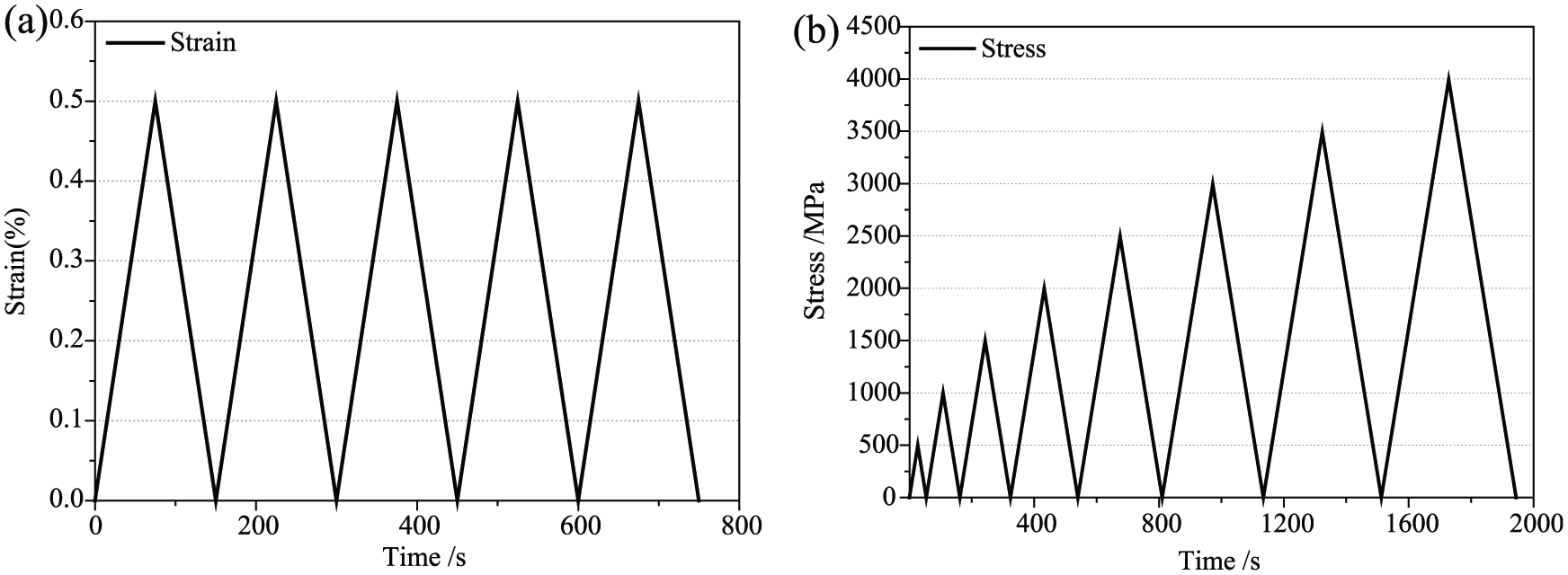
Two types of loading–unloading cycles for CFRP “plain”/modified laminates.

(a) Experimental machine testing set-up and electrical contact configuration of stretched samples and (b) the schematic diagram of test circuit.
Results and discussion
CNFs/EP composites
Figure 4 shows the scanning electron microscopy (SEM) images of fracture section of CNFs/EP composites with different contents of CNFs. It can be seen that the CNFs were evenly distributed and dispersed in composite matrix. In comparison, micron fiber network of 1.0 wt% of CNFs is more intensive, and the percolation network is more perfect.

SEM images of fracture section of CNFs/EP composites: (a) 0.5 wt% and (b) 1.0 wt% CNFs.
Figure 5 presents the strain and resistance response of CNFs/EP composites versus time under incremental tensile loading. Each type of specimen was measured at least five, and the same resistance change curve was observed for each type specimen. The valid and smooth signal showed the stable electrical conductivity of the two-phase composites. CNFs as conductive phase are almost uniformly distributed in the matrix, and it is easy to overlap each other and form conductive network because of their large aspect ratio. We can see that the electrical resistance values follow closely the strain trends of materials, and the correlations between changes in resistance and the microstructure damage can be established by a closer analysis. In all cases, the CNFs network in matrix produced deformation along with specimen when they are under stress. The changes of networks resulted in the loss of CNFs contacts, which leaded to an increased resistance of the specimens. Similarly, the contact points of conductive percolation network recovered with the decrease in the specimen strain, and resistance is reduced to the original value. It is very interesting that with the increase in cycling times, each strain peak corresponding to the greater change of resistance and the residual resistance increased gradually. This is due to the micro-cracks generated progressively in composites during loading, and part of the conductive network is destroyed because of the continuous development and evolution of cracks. As expected, an increase in the residual strain can be clearly observed in Figure 5. As seen in Figure 5(a), the resistance of 0.5 wt% CNFs contents fluctuated obviously while the irreversible electrical resistance change appeared. This phenomenon can be explained as the conductive network, which has been destroyed, moved, and deformed with the deformation of specimen, thus resulting in the unstable state of contact points. As for the EP with 1.0 wt% CNFs, there was no significant fluctuation of resistance under the same load condition due to the relatively perfect conducting system, which was less influenced by conductive particles move. At the same time, the rate of resistance change in the Figure 5(b) was lower at the same level of stress and strain. In other words, the strain sensitivity of the resistance decreased due to the denser conductive network. But it is worth noting that the irreversible electrical resistance in Figure 5(b) changed more obviously than Figure 5(a) at the same strain level, which can be understood by a lower inherent resistance in coupons with higher content of CNFs. Therefore, the higher content of CNFs may be a better choice for self-sensing the damage degree of testing coupons.

Strain and resistance-change response of CNFs/EP composites under incremental cyclic loading: (a) 0.5 wt% and (b) 1.0 wt% CNFs.
CNFs/CFRP laminates
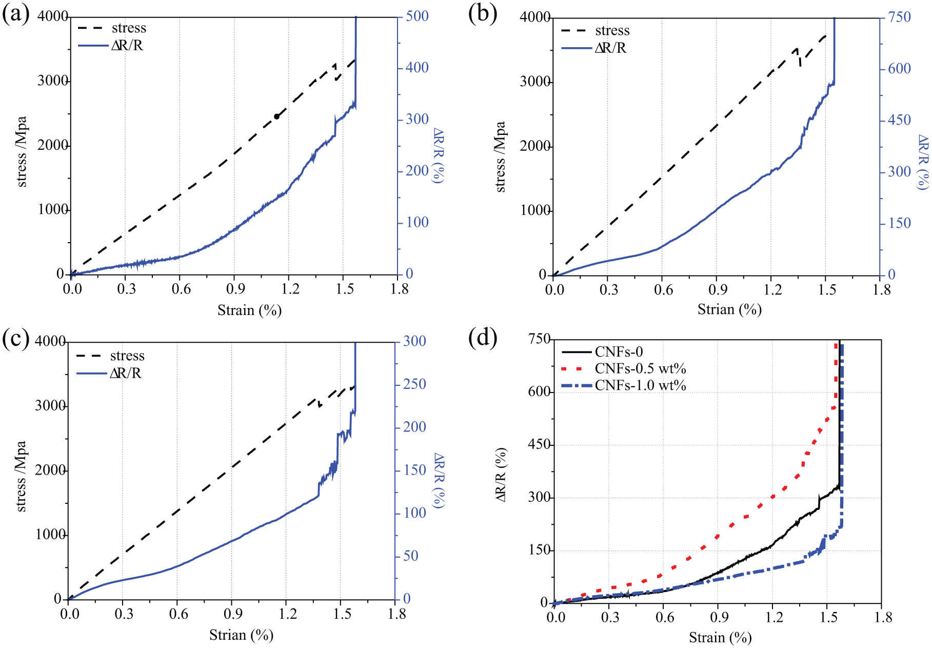
The resistance–strain response curves of CFRP with different contents of CNFs under constant amplitude cyclic tensile loading were given in Figure 6. The strain returned to zero at the end of each cycle. The changes in resistance during loading caused by the deformation of the nano-particle filler is so small that it can be ignored compared with variation of global conductive network caused by deformation of specimen. And the response of resistance was essentially corresponding to the strain of composites. Due to the presence of high conductivity CFs, the resistance response had a better linearity and relatively little noise compared to CNFs/EP composites. The detected resistance signal had the same trends to the low strain level among the continuous loading process. The conductive phase was away from each other when composites were deformed; as a result, the decrease in percolation network contact point increased the resistance. However, conductive network recovered with the reduction of the material strain, and the resistance decreased to the initial value. The complete uninstall of strain without residual resistance indicated that there was no irreversible damage in composites at the low strain level. Considering that the curves of resistance, without resistance drift, almost remained the same shape in continuous loops, we can draw that the self-sensing properties of CNFs/EP composites are stable and reliable. Figure 6(d) demonstrates the comparison of ΔR/R0 for different CNFs contents of specimens corresponding to the same strain level in a loading process. The slope of ΔR/R0 for strain is not linearly increasing mainly due to the influence of the tunnel effect resistance, which increased exponentially with the distance between the conductive particles. For CFRP laminates which are modified by a appropriate content of CNFs (0.5 wt%), it was easy to find that the resistance sensitivity increased at the same strain level. A representative SEM image for CNFs/CFRP laminates is shown in Figure 7. As the reinforced material, CNFs can be easily found in the epoxy matrix, which provided additional conductive path between the single CFs and fiber layers. In this case, three-dimensional conductive paths were formed in the composite material, and the conductive paths in matrix eliminated the influence from the random conducts between the CFs. Therefore, the CNF-enhanced CFRP laminates can not only monitor the CF system but also equip the internal insulation matrix with the function of self-sensing. In short, the incorporation of the CNFs further perfected the self-sensing function of CFRP laminates, and composites strain sensitivity was improved. It is noteworthy that there was a lower material strain sensitivity corresponding to a large mass of CNFs (1.0 wt%). This phenomenon can be explained that the excessive conductive fillers resulted in a redundancy conductive system, and overlapping laps formed between CNFs and CFs, so the electric conductivity of composites was affected less by strain and damage. The high strain sensitivity is necessary for self-sensing of the composites, and it is important to choose an adequate quality of CNFs to modify CFRP laminates at the low strain level.

Strain and resistance-change response of CNFs/CFRP laminates under constant amplitude cyclic tensile loading: (a) “plain” CFRP, (b) 0.5 wt% CNFs, (c) 1.0 wt% CNFs, and (d) comparison of different CNFs contents.

SEM image of fracture section of CNFs/CFRP laminates.
Figure 8 shows the response of strain–time and resistance of “plain” and CNFs-reinforced CFRP coupons under quasi-static tension loading. The presence of highly conductive CFs play a leading role in the mechanical properties of composites, and the stress–strain curves exhibit good linear elastic response. Consistent with the conclusion of many studies, the tensile strength of CFRP slightly ascended as the result of adding a moderate amount of CNFs (0.5 wt%). The trends of three resistance curves in Figure 8(a)–(c) aligned fairly well. Based on the resistance-change data, the self-sensing feature of composites under quasi-static tension loading until destruction can be divided into three stages for analysis. The first phase was from the beginning to a strain level of about 0.5%–0.6%, the change of resistance was mainly caused by the elastic deformation of the matrix and micro-cracks in interior materials. Preliminary damage affected the conductive contact points between CFs (“plain” CFRP) or CNFs and CFs, and the resistance–strain curves showed almost linear growth. In this case, the material strain is reversible and the micro-cracks can be closed when unloading. The second phase was extended to a strain level of about 1.2%–1.3%, the micro-cracks developed gradually into thorough crack, and the matrix damaged severely. Part of CFs fractured at the site of injury; CNFs have been pulled off or pulled out from the matrix in the specimen. Thus, the percolation networks were destroyed seriously at this stage, and the rate of change in resistance of the specimen increased, which is shown in Figure 8 that the slope of resistance–strain curves increased rapidly. The final phase was extended to the final fracture of composites. In this process, the main damage mechanism is the failure of the residual CFs. Every time the serious damage occurred, there would be a sudden increase in resistance. And the resistance was a sharp rise at the time of final destruction. Figure 8(d) presents the comparison of resistance response of “plain” CFRP and CFRP with different CNFs contents under quasi-static tension loading. The strain sensitivity of CFRP specimen was raised due to the addition of conductive fillers, and it is particularly noteworthy that the maximum resistance change of CNFs/CFRP corresponding to the final damage was almost twice than that of “plain” CFRP. Due to the presence of conductive network in CNFs/CFRP matrix, the development of cracks in matrix can be self-sensed by the composites based on the first stage of recoverable deformation. Compared to “plain” CFRP, CNFs/EP resistance response included the self-sensing for matrix damage; as a result, the strain sensitivity would be greatly improved. However, the strain sensitivity of CNFs/CFRP laminate reduced when CNFs content reached 1 wt%, even lower than that of the “plain” CFRP. In response to this phenomenon, a new explanation except the view mentioned above was given as follows. There were two conductive mechanisms in loading process until complete failure, including the destruction and regeneration of conductive paths. The conductive paths, which were destroyed by deformation or microscopic damage of composites, produced displacement and rotation due to further stretch, and part of the remaining conductive network re-lapped and reduced the rate of resistance change.
Strain and resistance-change response of CNFs/CFRP laminates under quasi-static tension loading: (a) “plain” CFRP, (b) 0.5 wt% CNFs, (c) 1.0 wt% CNFs, and (d) comparison of different CNFs contents.
Figure 9(a)–(c) shows the strain and resistance change of composites under incremental cyclic loading. From the figures, we can easily find that the body resistance presented a linear growth with the increase in cycling times from the second cycle. The generation of macroscopic residual resistance indicated that the damage had formed in composites and part of the conductive path had been broken. The increase in residual strain found in the strain curve derived from the accumulation of damage in materials, which further confirmed the above view. The conductive networks were stretched and even damaged due to the generation of cracks during cycles, so the generation and development of cracks in the specimens can be clearly monitored by the resistance-change response. And the increased body resistance of materials provides information for CFRP damage self-sensing. The resistance-change response of “plain” CFRP and CFRP with 0.5 wt% CNFs in the seventh cycle were shown in Figure 9(d) and (e). A same analysis by Gao 18 noted that there were three phases of resistance response corresponding to the material damage in loading process, including cracks reopened, elastic deformation of the matrix cracks, and the formation of new cracks. Compared to the “plain” CFRP, which can only perceive the fracture of CFs and the decrease in contact points between CFs, the CFRP modified with 0.5 wt% CNFs has the ability to sense the interface damage between CFs and matrix and the formation and development of cracks in matrix. As a result, there was a more obvious change in resistance, especially in the stage of elastic deformation and matrix crack formation, and there was a significantly larger slope of the resistance change in Figure 9(e) than Figure 9(d). So the damage information of material matrix and reinforcing fibers can be obtained through resistance response in the process of loading and can also self-sense damage and the extent of the damage that has been formed inside the material. However, the failure process was not clearly self-sensed in the composite with 1.0 wt% CNFs as a result of the intensive and overlapping percolation network. At the same time, excessive CNFs leaded to the increase in viscosity and the decrease in fluidity of epoxy matrix. The impregnation of CNFs/EP mixture deteriorated during the hand lay-up method of operation, which resulted in a lower layer performance between CFRP and caused the early damage. The schematic of resistance change in crack evolution of CFRP (0.5 wt% CNFs) in the seventh circle was shown in Figure 9(f), and we can still clearly observe the complete processes of crack reopening, elastic deformation, and the new crack formation corresponding to Figure 9(e). And it is worth noting that there was a hysteresis effect in resistance that the resistance value during load at each cycle was less than the resistance value of the last cycle of unloading because of the time-consuming rack closure and reopening. Figure 9(g) shows the resistance cycle of CFRP (0.5 wt% CNFs) in the process of the cyclic loading. In addition to the self-sensing information described above, it seemed that there was a significant increase in the slope of the resistance in each cycle when the strain reached the maximum of the previous cycle, which corresponds to the new injury. The above phenomenon was corresponding to the process of new crack formation in Figure 9(e), and the Y-intercept of the resistance curve at this stage was equal to the damaged resistance in each loading cycle. Throughout the loading process, the real-time self-sensing can be achieved through observing the slope of the resistance-change curves and quantifying the amount of material damage further.

Strain and resistance-change response of CNFs/CFRP laminates under incremental cyclic loading: (a) “plain” CFRP, (b) 0.5 wt% CNFs, (c) 1.0 wt% CNFs, crack reopen and formation in seventh cyclic loading: (d) “plain” CFRP and (e) 0.5 wt% CNFs, (f) resistance response in seventh cyclic loading, and (g) resistance response during incremental cyclic loading.
Through the analysis of resistance data got from the different tensile modes, a stable and reliable relationship has been established between the macroscopic resistance changes and the microscopic strain and internal failure of CNFs/EP and CNFs/CFRP laminates. Compared with several related studies about the self-monitoring capability of CFRP laminates modified with CNTs,25,29 the researches in this study not only achieved the purpose of material reinforcement but also perfected the self-sensing system of composites. At the same time, we were pleasantly surprised to find that all the resistance curves in our article appeared to be smoother compared with the other researchers’ test, in which the CFRP laminate was enhanced with CNTs and applied a similar loading. The above phenomenon further confirmed that CNFs were more easily dispersed evenly than CNTs because of their modest aspect ratio. Thus, there were fewer aggregates in conductive networks of CNFs, and the uniform conductive percolation network provided stable conductive paths and relatively little noise in the detection process. In short, CNFs have a higher cost-effective and a better application prospect in large-scale project.
Conclusion
The self-sensing capability of CFRP laminates with CNFs through ERT has been researched on the basis of studies of CNFs/EP, including the sensing of the deformation and damage accumulation caused by tensile loading. The relationship between the resistance changes and mechanical strain or damage of CFRP laminates was established. Based on the experimental results and analysis, the conclusions can be drawn as follows:
The resistance-change curve of CNFs/EP composites material followed the loading trace under incremental cyclic loading. The resistance of CNFs/EP changed due to the microscopic deformation or destruction of the circuit in matrix, which indicated changes in the internal structure of the composites. And the increase in the residual resistance indicated the irreversible damage formed in the composites. It is simple and feasible to use the resistance method to self-sense the strain as well as the damage of epoxy matrix without external monitor.
The self-sensing of CNFs-reinforced CFRP laminate can also be successfully achieved with the high strain sensitivity by ERT in different types of tensile loading. The characteristic allows the CFRP laminate to serve as a sensor of its own stress–strain state and degree of damage without reducing its mechanical properties. Due to the reproducibility and stable sensing performance, this method provides a new approach for in situ monitoring of CFRP laminates.
Footnotes
Academic Editor: Xiaotun Qiu
Declaration of conflicting interests
The author(s) declared no potential conflicts of interest with respect to the research, authorship, and/or publication of this article.
Funding
The author(s) disclosed receipt of the following financial support for the research, authorship, and/or publication of this article: This work was supported by the National Key Basic Research Program of China (project no. 2012CB026200) and the innovation fund of State Key Laboratory of Coastal and Offshore Engineering for Young Scholars (project no. LY1608).