
Abstract
Heavy oil is an important oil resource. The main development method is thermal exploitation—steam stimulation. Drastic variation in temperature will result in thermally induced micro-gaps in the first interface during steam stimulation. The existence of micro-gaps will cause steam channeling in the hole and difficulty in engineering logging interpretation. According to the stress of casing string of thermal production wells and thermal injection model, the mechanical model of casing string of thermal production wells is divided into four intervals for further analysis, including the wellhead movement extension interval, the extension and compression movement interval between low-temperature zones, the packer movement interval, and the extension and compression movement interval between perforation sections. For different casing string intervals, two types of mathematical models of first interface micro-gap width are established. In order to comprehensively evaluate the micro-gaps, the mathematical model comprehensively evaluating cement sheath micro-gaps is established through superposition and geometric mean of two models. The models can be used to calculate the first interface micro-gap width of different intervals. In addition, the tri-strata axial symmetric finite element model of first interface with micro-gap is established, and the variation in temperature field, stress field, and width of micro-gap interval of wellbore is analyzed, which provides the theoretical basis for evaluation of micro-gaps.
Introduction
Heavy oil is an important oil resource. The main development method is thermal exploitation.1–3 During steam injection recovery of heavy oil, the variation in temperature inside wellbore would result in thermally induced micro-gaps in the first interface. The reason for micro-gaps is that the casing, cement sheath, and borehole wall suffer from heating expansion because of warming inside wellbore, the cement sheath is compressed by the casing, and the formation is compressed by cement sheath in radial direction because of different expansion speeds; after shut in well, the casing, cement sheath, and borehole wall suffer from shrinkage deformation because of cooling, the interfaces are separated under tensile stress because of different shrinkage speeds, and the micro-gaps are generated.4,5 Generally, the micro-gaps can seal oil but not steam. Thus, during steam injection recovery of heavy oil, the micro-gaps would result in channeling outside casing and decrease bottom hole steam dryness and steam injection volume, and the heavy oil in formation could not be effectively produced.
In China, the well logging engineering staffs have conducted a large amount of qualitative research on the micro-gaps,6–10 and most of them believed that there are micro-gaps. However, there is little research on quantitative calculation of micro-gaps. In this article, the first interface micro-gap formed during steam huff and puff was quantitatively researched and the mathematical models of first interface micro-gap width were established. The models could be used to calculate the first interface micro-gap width of different intervals.
There is abundant heavy oil resource in the XZ Oilfield, and the heavy oil is mainly produced by steam stimulation. Before steam stimulation, 92% of oil wells have favorable cement sheath bonding quality, and the first interface between casing and cement sheath has no micro-gaps. Therefore, when establishing the mathematical model of the first interface micro-gaps, it was assumed that there is favorable bonding between cement sheath and casing before steam injection and the micro-gap does not exist. At present, the technology of detecting second interface micro-gaps between cement sheath and formation through well logging is still not mature in China. Thus, in case of easily studying the first interface with micro-gaps, it was assumed that the second interface has favorable bonding quality. According to stress of casing string of thermal production wells and thermal injection model of studying area, the mechanical model of casing string was divided into four intervals for further analysis, and the mathematical models of first interface micro-gap width of different intervals were established. The models could be used to calculate the first interface micro-gap width of different intervals. In addition, the tri-strata axial symmetric finite element models of first interface with micro-gaps were established, and the variation in temperature field, stress field, and width of micro-gap interval of wellbore was analyzed, which provides the theoretical basis for evaluation of micro-gaps.
Interval division of mechanical model of casing string
According to stress of casing string of thermal production wells and thermal injection model in the XZ oilfield, the mechanical model of casing string is divided into four intervals, which are shown in Figure 1. The first is the wellhead movement extension interval, and its extension length is related to the thermal insulation model, the rock mechanical properties of formation, and the size and mechanical properties of casing. The second is the extension and compression movement interval between low-temperature zones. Compared with the temperature variation below packer, the temperature of this interval is low and related to the thermal insulation model. The interval is called as “low temperature zone.” Compared with the wellhead movement extension interval, the “low temperature zone” interval is a pseudo-anchoring interval, and axial displacement of whole interval is zero. The third is the packer movement interval, where the big variation in temperature above and below packer exists, and it is divided into one interval in the study. The fourth is the extension and compression movement interval between perforation sections, which is the reservoir interval and has soft formation, the formation depletion tends to occur, and the interval is the high-temperature zone of whole well section. Compared with the wellhead movement extension interval, the “high temperature zone” interval is also a pseudo-anchoring interval, and the axial displacement of whole interval is zero.
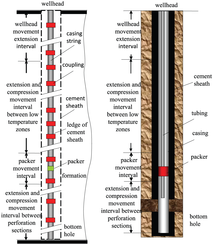
Mechanical model of casing string in thermal production well.
Mathematical model evaluating cement sheath micro-gaps during heavy oil thermal recovery
Calculation model I of the first interface micro-gaps
In this article, three kinds of calculation models of the first interface micro-gap width are introduced. The calculation and derivation methods of model I and model II are different, and the third model (comprehensive model) is obtained through superposition and geometric mean of model I and model II.
Based on the literatures,11–13 the calculation model

where
Evaluation of micro-gaps below and above packer
The micro-gap below packer is the largest micro-gap between perforation interval and packer. The micro-gap above packer is the largest micro-gap between packer and bottom of wellhead movement extension interval. Both micro-gaps are calculated with formula (1), and their differences are mainly the variation in temperature. The former resulted from high-temperature zone, and the latter resulted from low-temperature zone. The different variations in temperature results in the difference in elasticity modulus E, thermal expansion coefficient
Calculation of micro-gaps of wellhead movement extension interval
The calculation of micro-gaps of the wellhead movement extension interval is different from that in the low-temperature zone and the high-temperature zone. The comprehensive extension displacement of casing is zero in the low-temperature zone and the high-temperature zone, which is seemingly a “pseudo anchoring” interval (below wellhead extension movement interval), and it is calculated with formula (1). However, the wellhead movement extension interval is fixed by “pseudo anchoring” in its bottom, and the casing suffers from extension from fixed point to wellhead. It is assumed that the casing deformation is within the scope of elastic variation. The variation in density of casing material is neglected. According to the principle of invariable volume, it is believed that when the casing is extended in axial direction, it is shrunk in radial direction and the micro-gaps occur between casing and cement sheath. In case of cooling, the casing returns to its original position and part of micro-gap is offset. The micro-gap resulted from casing extension is expressed with


According to the principle of invariable volume, it is obtained by combining formulae (2) and (3)

Thus, the micro-gaps resulted from casing extension are calculated with
After cooling, the micro-gap width of wellhead movement extension interval

where
Calculation model II of first interface micro-gaps
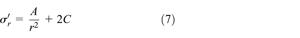
Assuming that the casing pressure is Pa, casing inner radius a, external radius b, and expansion coefficient α, according to the Lame formula of thick wall in elastic mechanics, the radial stress

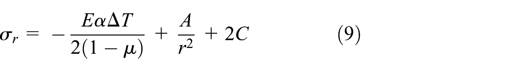
When considering the temperature effect, the radial stress
Boundary conditions
The radial expansion of casing occurs because of variation in casing pressure and temperature; when the casing pressure decreases or vanishes, and temperature decreases, the radial shrinkage of casing occurs. The cement sheath is brittle material, and its shrinking percentage is less than the shrinking percentage of casing. Thus, the micro-gaps are generated between casing and cement sheath, and the contact pressure (external pressure) of external wall on casing is zero, which are the boundary conditions of generating micro-gaps, namely

The variation in pressure in the inner wall of casing is equal to the variation in casing pressure, Pa. The static fluid column pressure is constant, and the boundary condition in the inner wall of casing is

Thus, according to formulae (9), (11), and (12), the coefficients A and C are expressed as


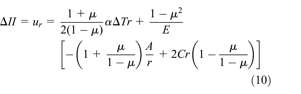
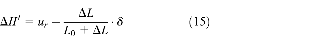
The calculation model II of first interface micro-gaps, formula (10), could be used to calculate the micro-gaps of “pseudo anchoring” intervals below and above packer. For the wellhead movement extension interval, its micro-gap width could also be calculated with formula (15), namely
Comprehensive model of first interface micro-gaps
Two mathematical models evaluating micro-gaps resulted from temperature variation were derived above with different methods. The micro-gaps could be calculated with both models. The variation form and magnitude of micro-gap with temperature calculated by two models are similar. In order to comprehensively evaluate the micro-gaps, the mathematical models evaluating cement sheath micro-gaps were established through superposition and geometric mean of two models. The comprehensive evaluation mathematical models of models I and II are written as
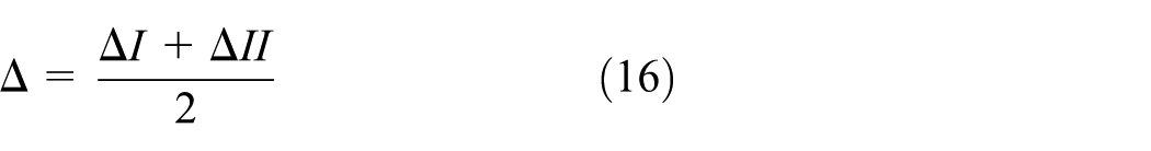

Formula (16) is applicable to evaluation of the cement sheath micro-gap width of “pseudo anchoring” intervals below and above packer. Formula (17) is applicable to evaluation of micro-gap width of the wellhead movement extension interval.
Example
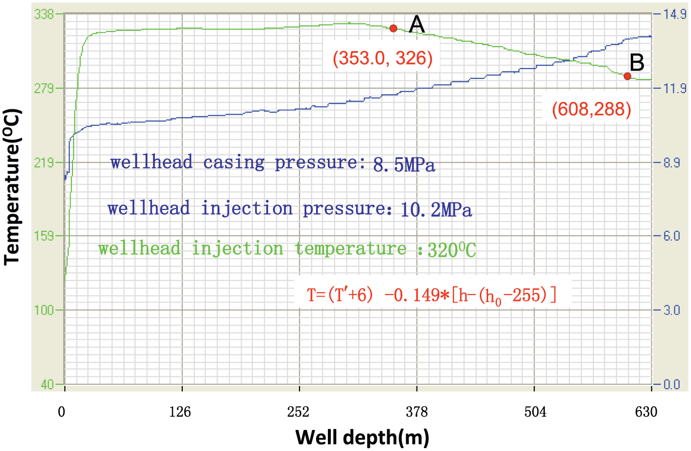
A well of the XZ Oilfield was analyzed. The downhole string: Φ88 mm × 50 mm (inner radius) vacuum thermal insulation pipe + K332-115 thermo sensitive packer at 608.2 m; pay formation between 613.2 and 627.4 m; casing: 139.7 mm × 7.72 mm; maximum inclination: 1°12′; and artificial bottom hole: 686.0 m. According to the measured temperature curves, shown in Figure 2, the mathematic models of temperature T of casing string along well depth are established, as shown in formulae (18) and (19).
Temperature of casing above the packer

Temperature of casing below the packer

where T′ is the wellhead steam injection temperature, °C; h the well depth, m; and h0 the position of packer, m.
The measured temperature curves of casing along well depth.
The micro-gaps of different intervals are calculated with the comprehensive model. At the end of steam injection, it is shown in Figure 3 that in high-temperature zone below packer, the micro-gap of the first interface is 0.3576 mm; between packer and bottom of the wellhead movement extension interval, the micro-gap of the first interface is 0.1119 mm; and inside the wellhead movement extension interval, the micro-gap of the first interface is 0.1001 mm. The largest micro-gap mainly occurred in the perforation high-temperature zone below packer; the smallest micro-gap mainly occurred inside the wellhead movement extension interval.
Relation between micro-gaps and steam injection temperature.
Analysis of thermal recovery wellbore with micro-gaps in first interface
According to the range of micro-gap width reflected in the field well logging data and calculated by the mathematical models of micro-gaps derived in the article, the tri-strata axial symmetric finite element models of first interface with micro-gaps were established with the micro-gap width of 0.15 mm and axial length of 4 m. It is found in well logging data that the micro-gaps generally occur inside the sandstone layers. Thus, it is assumed that the micro-gap is located in the upper sandstone interval; the distance between micro-gap top and the studying interval top is 2 m, and the distance between micro-gap bottom and interface of sandstone and mudstone is 1 m. The axial symmetric model is shown in Figure 4. The parameters of materials and steam injection of wellbore are shown in Tables 1 and 2.

Tri-strata axial symmetric physical model of the first interface with micro-gap.
Parameters of thermal transmission.

Thermomechanical parameters.

Analysis of temperature field
It is shown in Figures 5 and 6 that at the end of steam injection, the temperature of casing outer wall in micro-gap interval reaches the maximum of 313°C, which is evidently higher than that in other intervals. The reason is that the micro-gap interval has changed the heat transfer mode of medium around the micro-gap. During steam injection, the heat is injected into the wellbore constantly, and the casing temperature in the micro-gap does not diffuse rapidly through other medium. Thus, the temperature of casing outer wall in the micro-gap interval is higher than that in other intervals. During shut in well, the heat is not injected. The temperature inside wellbore decreases constantly as the time of shut in well passes, but the temperature of casing in the micro-gap interval decreases rapidly. Thus, at the end of shut in well, the temperature of casing in the micro-gap interval is lower than that in other intervals. The heat transfer parameters of the mudstone layer are different from that of sandstone layers; hence, the casing temperature in mudstone interval is higher than that in sandstone intervals.

Temperature of casing outer wall at the end of steam injection.
Temperature of casing outer wall at the end of soak.
The temperature distribution of cement sheath inner wall along the axis of wellbore at the end of steam injection and soak is shown in Figures 7 and 8. Because of the micro-gap, the temperature of wellbore could not be effectively transmitted to the cement inner wall corresponding to the micro-gap interval. Thus, the cement temperature in micro-gap interval is evidently lower than that in other intervals.

Temperature of cement sheath inner wall at the end of steam injection.

Temperature of cement sheath inner wall at the end of soak.
Analysis of stress field
It is shown in Tables 3 and 4 that at the end of steam injection, the maximum equivalent stress of casing is 178 MPa at the top of mudstone interval. The casing equivalent stress in micro-gap interval is 50 MPa. Compared with the casing stress under cement strong bonding, the peak of casing equivalent stress with micro-gap existing in the first interface is very small and far less than yield limit of casing material. The reason is that with the micro-gaps, part of restrained casing is relieved under the temperature field and could be extended freely. Thus, the thermal stress of casing is smaller.
Peak of stress of whole casing string (MPa).
Stress of casing in micro-gap interval (MPa).

Analysis of variation in micro-gap width
In order to study the variation in micro-gap width during steam injection cycle, the radial displacement of casing outer wall and cement sheath inner wall and the contact pressure between them along the path a-b in Figure 4 were analyzed.
It is shown in Figures 9 and 10 that along the path a-b, a large radial displacement occurs in casing of the micro-gap interval at the end of steam injection, the radial displacement of casing decreases at the end of soak, and the distribution of displacement is relatively uniform. The distribution of radial displacement of cement sheath during injection and shut in well is non-uniform, the radial displacement of cement sheath ina-c section is positive (deviate from the casing), and that of c-b section is negative (close to the casing). When the sum of casing radial displacement and cement sheath radial displacement (close to the casing) is larger than or equal to the micro-gap width of 0.15 mm, the micro-gap is closed, and the contact pressure occurs between casing outer wall and cement sheath inner wall. It is shown in Figure 11 that the contact occurs in the section near a-end, with a contact pressure of 0.175 MPa at the end of steam injection. During soak, the wellbore temperature begins to decrease, and the casing and the cement sheath gradually shrink and are separated. The process is the variation in micro-gap width.
Radial displacement of casing in micro-gap interval.

Radial displacement of cement sheath in micro-gap interval.

Contact pressure between casing and cement sheath in micro-gap interval.
The micro-gap resulted from increasing and decreasing of wellbore temperature brings difficulty for acoustic amplitude logging. The relative amplitude of casing wave is large, and the micro-gap may be judged as channeling, which creates the error in the well cementation evaluation. The change mechanism of micro-gap in thermal production well was studied through finite element method, which provides the theoretical basis for evaluation of micro-gap.
Conclusion
The mechanical model of casing string in thermal production well is divided into four intervals for analysis, including wellhead movement extension interval, the extension and compression movement interval between low-temperature zones, the packer movement interval, and the extension and compression movement interval between perforation sections.
For different casing string intervals, two types of mathematical models of first interface micro-gap width were established. In order to evaluate the micro-gaps effectively, the comprehensive mathematical model evaluating micro-gaps was established through superposition and geometric mean of two models.
It is found in the result of calculating first interface micro-gap width in a well of the XZ Oilfield that the different intervals have different micro-gap widths, and the largest micro-gap mainly occurs in the perforation zone below packer.
The tri-strata axial symmetric finite element model of first interface with micro-gap was established, and the change mechanism of temperature field, stress field, and micro-gap width in wellbore was analyzed, which provides the theoretical basis for evaluation of micro-gaps.
Footnotes
Academic Editor: Oronzio Manca
Declaration of conflicting interests
The author(s) declared no potential conflicts of interest with respect to the research, authorship, and/or publication of this article.
Funding
The author(s) disclosed receipt of the following financial support for the research, authorship, and/or publication of this article: The authors are grateful to the support from the National Natural Science Foundation of China (No. 51574198).