
Abstract
An integration–rolling–extrusion process is raised for the manufacture of spline shaft in this study. First, the principle and procedures of integration–rolling–extrusion process are described. Next, the finite element model with a simplified sector blank is established to obtain a practical method for the simulation of integration-rolling-extrusion process. Through the simulation results, the plastic forming mechanisms are clearly revealed. During the integration–rolling–extrusion process, the equivalent stress, deformation degree, and material flow behavior mainly distribute on the surface layer of the blank and then gradually decrease along the radial inward direction. In the core region of the blank, there are almost no effective stress distribution, deformation degree, and material flow behavior. Next, the experiments are carried out on a specialized forming equipment to verify the finite element model. The results are measured and compared with finite element results. The finite element results show a good agreement with experiments; thus, the finite element analysis on the integration–rolling–extrusion process is credible. In addition, the measurement results show that the dimensions meet the requirement of heavy truck application. It indicates that the integration–rolling–extrusion process is feasible for the manufacture of spline shaft. However, the surface quality of the formed spline shaft is not satisfying, which needs to be discussed further.
Keywords
Introduction
Spline shafts are usually used as the key parts to transmit torque or motion between the shafts in mechanical equipment. The advantages of spline connection can be summarized as follows: high reliability, high connection strength, convenient assembly, and compact structure. 1 Thus, the various advantages of spline connection bring a huge demand of spline shafts in the industries such as automobile, engineering machinery, ship, and aerospace. For example, a standard car contains more than 30 spline shafts. As shown in Figure 1, the installed positions of spline shafts include transmission, differential, clutch, and so on.2,3 In addition, the modern industry brings a higher requirement to the manufacturing efficiency and performance of spline shaft. Therefore, it is urgent to study an advanced manufacturing process for the spline shaft.

Installation positions of the spline shaft in automobile: (a) clutch, (b) driving axle, (c) transmission assembly, (d) steering assembly, (e) differential, and (f) transmission.
The plastic forming is a kind of excellent manufacturing process, which has various advantages such as higher production efficiency, higher material utilization, and better mechanical properties. Recently, the plastic forming processes (rolling, extrusion, pressing, forging, and so on) have become the dominant manufacture methods for many universal parts. These parts include gear, spline shaft, thread, and ball screw.4–8 Meanwhile, the finite element analysis (FEA) was widely used to investigate advanced forming process. Through FEA, the stress and strain distribution, forming load variation, and material flow behavior during the forming process can be revealed.3,9–15
Hitherto, many studies were focused on the manufacturing process of spline shaft. According to the stress field of slip-line, the unit average pressure on contact surface during the gear rolling process was solved, and the formula of the rolling force and rolling moment was established by Zhang et al.12,13 Li et al. 14 have studied the material characteristic of 42CrMo during the warm forming process, and the effects of the main process parameters on the forming loads and tooth filled quality during the open-die warm extrusion process are investigated. Altinbalik and Ayer 15 have investigated a forward extrusion process of clover section from different billet diameters. Zhang and Zhao 16 proposed a new method for the forming of shaft that has both spline and thread. The new process was verified through finite element (FE) method. Similarly, using the FE method, the rolling process of high gears was studied by Kretzschmar et al. 17 Zou et al. 18 have designed the optimal die profile which yields more uniform surface-load distribution on die profile surface via integrating FEA during the hot extrusion process. The work can improve the die life in hot extrusion processes. Huang and Fu 19 studied and solved the bulging problem in the open-die cold extrusion of spline shaft. Neugebauer et al. 20 studied the gear manufacturing process, which was similar to the rolling process of spline shaft, and proposed some significant improvements to enhance the pitch accuracy and improve the ability of rolling high teeth gears.
However, there is still no plastic forming process of spline shaft which is applied in large-scale production. The main reason is the big reaction force during the forming process of spline shaft. The purpose of this work is to develop an advanced forming process of spline shaft, which is called integration–rolling–extrusion process (IREP). Using IREP, the spline shaft could be formed in the surface layer with incremental method, which can significantly reduce the reaction force and improve the forming precision in the production of spline shaft.
This article is organized as follows. In section “Principle of the IREP of spline shaft,” the principle of IREP is described and the main process procedures are given in detail. In section “Finite element modeling,” a simplified and practical FE model is established for the simulating of IREP. Next, the FEA is carried out in section “Results and discussion.” The plastic forming properties are investigated according to the FEA results. In order to verify the FE model, the experiments are carried out in a specialized forming equipment. The experimental verification results are presented in section “Experimental verification.” Finally, the conclusions of this article are drawn in section “Conclusion.”
Principle of the IREP of spline shaft
As shown in Figure 2, the forming system of IREP mainly includes rolling dies (three), rear-driven center, blank and front center (not shown in Figure 2). The three rolling dies are uniformly installed around the blank and rear-driven center. Each rolling die is divided into two parts along the axial direction: the entrance section with die angle

Rolling system of the IREP of spline shaft.
The main process procedures of IREP are described as follows: (1) the blank is secured by the front center and the rear-driven center. (2) The three rolling dies begin to rotate simultaneously with the speed
According to the forming system and procedures of IREP, a specialized alternating current (AC) servo forming machine for spline shaft is designed and manufactured. The picture of rolling position is shown in Figure 3. The rolling dies are driven by AC servo motors, and the radial position of the rolling dies could be automatically adjusted by some other AC servo motors. The front center is coupled with an air cylinder and could push the blank into the center of rolling dies along the axial direction.

The rolling position of the IREP experimental equipment.
FE modeling
Geometrical structure of the spline shaft and rolling die
The spline shaft studied in this article is derived from the half-axle of a heavy truck. The geometrical structure and tooth parameters of spline shaft are shown in Figure 4(a). Figure 4(b) shows the geometrical structure and tooth parameters of the rolling die which is used to form the spline shaft.

Geometrical structure and tooth parameters of the spline shaft and rolling die: (a) spline shaft and (b) rolling die.
Material model
In this work, the 42CrMo steel (American Grade: AISI4140) is adopted as the raw material of the spline shaft. Li et al. 21 have studied the plastic properties of 42CrMo in detail and draw a conclusion that 42CrMo is a great material for spline shaft because of a good balance of strength, toughness, and wear resistance. During the IREP, both the strain value and strain rate value are large. It is essential to include the contributing effects of strain hardening and strain rate hardening.
In addition, Wang and Zhang
22
had studied the temperature change of blank during the cold rolling process and found that the temperature just slightly increased after rolling. Thus, they used the material model without temperature factor in the research of numerical simulation on spline shaft in cold rolling forming and obtained a coincident simulation result with the experiment. Groche et al.
23
had analyzed the temperature change in the incremental bulk metal forming. They had drawn a conclusion that the temperature of blank almost had no change because of the small steps and short forming time. Therefore, the simplified Johnson–Cook (J-C) rigid-plastic material model is employed to simulate the deformational behavior of 42CrMo, in which the softening effect generated by the temperature increase in plastic deformation is neglected. The J-C model is expressed as equation (1).10,24–26 The material flow stress

In equation (1), A, B, C, n, and
Motion features conversion
The original process motion features of IREP are shown in Figure 5(a). When the rolling dies (A, B, and C) rotatewith the speed

Process motion features conversion: (a) original motion features and (b) converted motion features.
Thus, the motion features of IREP should be converted in FE model. According to the definition of the planetary gear system in mechanical theory, the process system and motion features of the IREP are similar to those of the planetary gear system. Thus, the original process system could be equivalently converted to the planetary gear form as shown in Figure 5(b). The motion features of the equivalent planetary gear system are described as follows: the spline shaft is fixed at the central axis, the rolling dies are mounted on the planet carrier (which is represented by the dashed box in Figure 5(b)) of the planetary gear system, and the central axis of the planet carrier is in the same position with that of the blank. After the above conversion, the movement of the blank is transferred to the rolling dies. In the original system, the rolling dies (A, B, and C) rotate with the speed
FE models
Due to the cycle repeatability of the teeth on the spline shaft, the forming process and characteristics of each tooth are very similar. Therefore, it is normal simplifying the circular blank into the sector blank. In the previous studies on the rolling, extrusion process of spline, the simplification on the circular blank has been widely adopted during FE simulations, and its feasibility is proved to be valid.12–14 So, the part of total teeth on the sector blank is adopted to simulate the IREP in this study.
Compared with the circular blank, the total element number of the sector blank experiences a decrease, which declined the computational works; thus, the efficiency of simulation could be improved. Higher accuracy was obtained due to the increasing of meshing density in the local part. Therefore, the FE models with the simplified sector blank for IREP are established through the DEFORM-3D software.
Figure 6(a) shows the simplified sector blank model, and 1/8 of the circular blank (i.e. 45° and 5 teeth) is selected. The positions of the rolling dies and the sector blank are in accordance with those of the circular blank model. Figure 6(b) shows the detailed blank geometry, constraint, and FE mesh. Especially, the symmetrical constraint is applied on both sides of the sector blank, and the mesh refinement (size ratio 0.1) is conducted in the surface layer (depth of 1.5 mm) as well.

FE models with sector blank: (a) all of the models and (b) details of the sector blank.
Process parameters and assumptions
The process parameters of the FE models are set as follows: blank temperature (20°C), axial infeed speed (1.5 mm/s), rotational speed
In addition, some assumptions were made in the simulations: (1) the material behavior is isotropic, (2) both the Bauschinger effects and the elastic recovery of material are not taken into account, (3) there is no ductile fracture, (4) the rolling dies are considered as rigid body, (5) the gravity and inertia force of the blank itself are neglected, and (6) the effect of heat transfer between the blank, rolling dies and environment is not taken into account because that the whole system is considered to be at constant temperature due to the short forming time and small incremental steps.13,22,23
Next, the FE simulations have been carried out and the sector blank model is employed to simulate the teeth forming process. The results during the IREP including material flow, stress, and strain distribution are discussed in detail.
Results and discussion
Equivalent stress distribution
Figure 7(a) shows the equivalent stress distribution characteristic of the formed spline shaft. The equivalent stress distributions of the pre-rolling region and the calibrating region are also illustrated. It is visually displayed that the equivalent stress mainly distributes in the local tooth region of the surface layer.

Effective stress distribution characteristic on the forming spline shaft: (a) overall effective stress distribution and(b) effective stress corresponding to different radii in the pre-rolling region.
Furthermore, the equivalent stress distribution characteristic in the pre-rolling region is employed to analyze. Figure 7(b) shows the equivalent stress corresponding to different radii along the radial direction. When the radius is less than 20 mm, the equivalent stress gradually increases to about 509 MPa along both the tooth profile and tooth space directions. Next, along the tooth profile direction, the equivalent stress gradually increases to its maximum 891 MPa as the radius increases from 20 to 24.5 mm, but it drops to about 820 MPa when the radius increases from 24.5 to 25 mm. Along the tooth space direction, the equivalent stress gradually increases from 509 to 1235 MPa as the radius value increases from 20 to 24.35 mm. The maximum equivalent stress in the tooth space region is about 28% larger than that in the tooth profile region.
In summary, the equivalent stress distribution characteristic during the IREP could be summarized as follows. The equivalent stress mainly distributes in the local tooth region of the surface layer on the blank. It gradually decreases along the radial inward direction, and in the core region of the blank, the equivalent stress is almost zero. The results demonstrate that the reaction force is mainly generated by a small amount of material in the surface layer; thus, the reaction force can be greatly reduced by IREP.
Effective strain distribution
Figure 8(a) shows the effective strain distribution characteristic during IREP. The effective strain distributions on the cross sections with the axial distance

Effective strain distribution characteristic of the formed spline shaft: (a) overall effective strain distribution and(b) effective strain corresponding to different radii and directions on the cross section
In detail, the effective strain values corresponding to different radii and directions on the cross section
It is worth discussing that the decrease in effective strain value, which indicates that the deformation degree is declining when the radius increases from 23.5 to 25.875 mm along the tooth profile direction. When forming, the material in the tooth space area would mainly flow along the radial inward direction under the rolling action of the rolling dies. As a result, the effective strain continues to rise along the tooth space direction. Differently, the material at the middle and top region of the tooth profile area could flow along the radial outward direction under the rolling action. Thus, the deformation degree of material relatively decreases in this area.
Therefore, the material deformation characteristic during the IREP could be summarized according to the effective strain distribution. The deformation mainly occurs in the surface layer of the formed spline shaft. Along the radial inward direction, the deformation degree gradually decreases and there is almost no deformation in the core region. The cross section of the formed spline shaft could be divided into three deformation regions according to the effective strain distribution along the radial direction. (1) No deformation region (radius less than 15 mm). (2) Small deformation region (radius from 15 to 20 mm). (3) Large deformation region (the surface layer of the formed spline shaft, radius from 20 to 25.875 mm). From the effective strain results, it can be concluded that the material in the surface layer of spline shaft has enough deformation degree in the IREP; thus, the high surface quality could be obtained.
Material flow characteristic
The final forming accuracy of the spline shaft is seriously affected by the material flow behavior. During the IREP, the material of blank experiences an obvious plastic flow under the pre-rolling and calibrating of rolling dies. The simulation results of material flow are valuable for understanding process and improving forming accuracy of IREP.
Figure 9(a) shows the material flow velocity distribution characteristic of the spline shaft. In the tooth profile area, the flow direction of material is basically radial outward. However, the material flow velocity shows a small axial component in the pre-rolling region due to the axial infeed action.
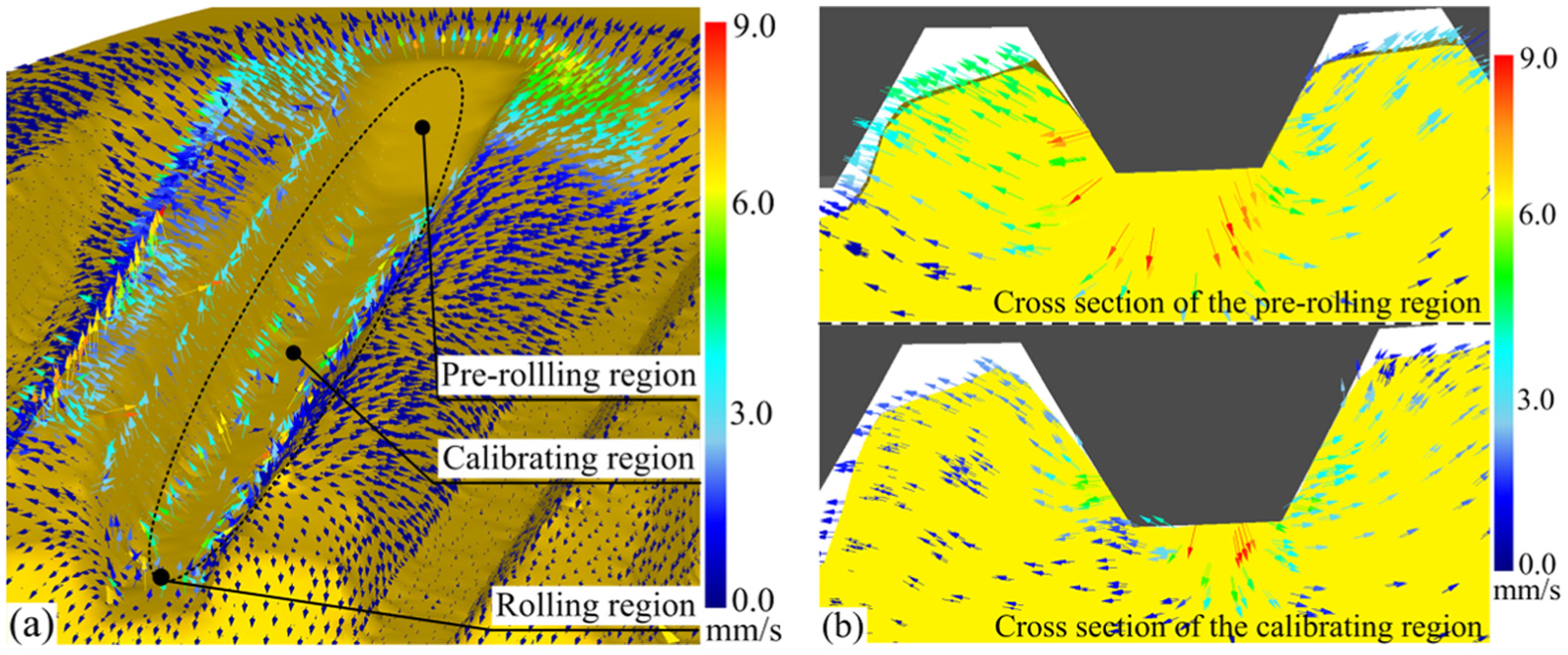
Material flow velocity distribution on the formed spline shaft: (a) 3D view and (b) 2D view of cross sections.
Figure 9(b) shows the material flow velocity distributions of the cross sections in the pre-rolling region and the calibrating region. In the pre-rolling region, the material of the tooth space area mainly flows along the radial inward direction, which generates the pressure action on the material of tooth profile in the adjacent area. Under this pressure action, the material of tooth profile area flows along the radial outward direction and then the tooth height gradually increases. In the calibrating region, the material flow velocity distribution is similar to that of the pre-rolling region. Specially, the material flow velocity is relatively weakened because the material flow behavior caused by plastic deformation is reduced.
Furthermore, the material displacement simulation results of the formed spline shaft are employed to reflect the deformation accumulation degree of material during the IREP. Figure 10(a) shows the material displacement distribution of the formed spline shaft, and the material displacement distributions on the cross section with the axial distance

Material displacement distribution characteristic of the formed spline shaft: (a) the material displacement distributions of the whole blank and the specific cross sections and (b) material displacement values corresponding to different radii on the cross section
In addition, the material displacement values (including the radial displacement and axial displacement) corresponding to different radii on the cross section
In the tooth profile area, the radial material displacement value along the radial inward direction gradually increases from −0.24 to −0.3 mm as the radius increases from 20 to 23 mm, but it rapidly decreases to zero as the radius increases from 23 to 24.75 mm. Then, the displacement direction changes to the radial outward direction and displacement value sharply increases to about 0.7 mm as the radius value increases from 24.75 to 25.875 mm. Meanwhile, the axial displacement value gradually increases to −0.49 mm as the radius increases from 20 to 24 mm, but it decreases to −0.2 mm as the radius value increases from 24 to 25.875 mm. Obviously, the radial material displacement is larger than the axial material displacement, which demonstrates that the material mainly flows along the radial direction in the tooth profile area during the IREP.
In the tooth space area, the radial and axial material displacement values along the radial inward direction gradually increase from 0 to −0.98 mm and −0.71 mm, respectively, as the radius value increases from 20 to 24.35 mm. The radial material displacement value is almost equal to the axial displacement value, which demonstrates that the material flows along both the radial and axial directions in the tooth space area during the IREP.
In summary, the material flow characteristic during the IREP is summarized as follows. The material flow behavior mainly appears on the surface layer of the formed spline shaft, and there is almost no material flow in the core of blank. The results demonstrate that the IREP can obviously reduce the flow behavior of core material.
In addition, the radial material flow components in the tooth profile area and tooth space area are mainly caused by the pre-rolling of the rolling dies (entrance part). The axial material flow leads to the decline of tooth height, which is negative for the forming accuracy. Thus, the axial material flow should be given enough consideration in the application of IREP.
In the above simulations, the axial infeed speed (1.5 mm/s) is selected based on a series of simulations which are set to feed with different speeds. The slower the axial infeed speed is, the smaller the axial mater flow is. However, the too small infeed speed will increase the time of entire process and make the IREP no worth for the practice production. On the basis of the results with different axial infeed speeds, the reasonable infeed speed is recommended as 1.5 mm/s and the maximum speed is given as 2.5 mm/s to avoid the large axial material flow.
From the above discussion, using the IREP, the flow behavior of core material is effectively avoided and the axial flow of the material in surface layer could be reduced by selecting a reasonable infeed speed. Therefore, a high forming precision in the production of spline shaft can be realized by IREP, thanks to the significantly reduced flow behavior in axial direction.
Experimental verification
A physical verification of the FE model is necessary for the reliability of the results. Through the specialized forming equipment, the relevant experiments are carried out. As shown in Figure 11(a), the blank is machined with diameter of 50.15 mm. The experimental procedures are as follows. The rolling dies are driven to rotate with speed of 20 r/min by AC servo motors and then the rear-driven center and the blank would be driven to rotate with the speed of 60 r/min. The blank is pushed forward with the speed of 1.5 mm/s by the air cylinder. The entire forming time of single blank is less than 60 s, and Figure 11(b) shows the final spline shaft. Compared with the experimental results, the FE results show a same tooth number with 1/8 of the circular blank, as shown in Figure 11(c).
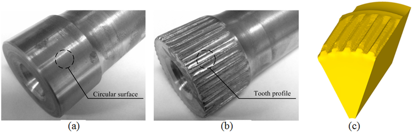
The blank and product: (a) blank, (b) formed spline shaft, and (c) formed spline shaft by FE model.
Furthermore, the shapes of the teeth on the formed spline shaft are measured to compare with FE results. The measurement results are listed in Table 1. The tooth parameters of FE model show a good agreement with the experimental results, which indicates that the FE models are credible. Therefore, the FE analysis results on the IREP are useful and could be used as a guide for the application of IREP. Moreover, the parameters of the formed spline shafts meet the requirement of theoretical. This demonstrates that the adapted process parameters are reasonable and the IREP is feasible to manufacture the spline shaft of heavy truck.
The measurement results of tooth shape.
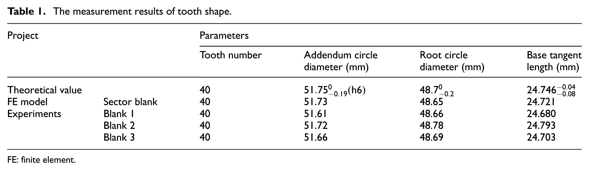
FE: finite element.
However, there is also a problem could be found in Figure 11(b). The surface quality of the formed spline shaft is not satisfying. After careful observation and analysis, two main reasons are determined: one is that the lubrication conditions are poor between the blank and rolling dies and the other is that the air cylinder feed system is unsteady during the infeed procedures.
Conclusion
Through the numerical and experimental studies above, the conclusions are drawn as follows:
A new plastic forming process of spline shaft called IREP is proposed to solve the present problem of large reaction force on rolling dies. The IREP uses an incremental forming method; thus, the rolling forces during the process are greatly reduced.
The FE models with the simplified sector blank for the IREP of spline shaft are established. The final formed spline shafts with the simplified FE models are in good agreement with the experiments. The tooth number and profile of the formed spline shaft are accurate through the dimensions measurement. Thus, the IREP of spline shaft is feasible and the simulation results are credible.
Through the FE results of IREP, the equivalent stress and the material flow mainly distribute on the surface layer of the blank. They gradually decrease along the radial inward direction, and the equivalent stress and material flow are almost zero in the core region. Especially, the stress results show that the maximum equivalent stress of the tooth space region (1235 MPa) is relative larger about 28% than that of the tooth profile region (891 MPa). This result warns us to pay more attention to the forming defect in tooth space region. There is also evidence shows that the axial material flow component, which is negative for the forming accuracy, is mainly influenced by the axial infeed speed. Therefore, the reasonable infeed speed is recommended as 1.5 mm/s and the maximum speed is given as 2.5 mm/s to avoid the large axial material flow.
During the IREP, the deformation degree, which is expressed by the effective strain, shows the same characteristics with the equivalent stress and material flow. In addition, the maximum effective strain in the tooth space region (12.57) is relative larger about 42% than that in the tooth profile region (7.24). This indicates that the surface of tooth space region has a larger hardness than that of tooth profile region. Therefore, based on the FE analysis in this article, it can be concluded that a smaller reaction force and a better forming precision are achieved using IREP.
Through the experimental verification, the feasibility of the IREP is verified. However, a new problem has also been found. The surface quality of the formed spline shaft is not satisfying and there are two main reasons. One is that the lubrication conditions are poor between the blank and rolling dies and the other one is that the air cylinder feed system is unsteady during the infeed procedures. These aspects are the major points of the next research on the IREP of spline shaft.
Footnotes
Academic Editor: Xichun Luo
Declaration of conflicting interests
The author(s) declared no potential conflicts of interest with respect to the research, authorship, and/or publication of this article.
Funding
The author(s) disclosed receipt of the following financial support for the research, authorship, and/or publication of this article: The authors are grateful to the National Natural Science Foundation of China for key program (grant no. 51335009), National Natural Science Foundation of China (grant no. 51305334), and Shaanxi Province Postdoctoral Science Research Program of China.