
Abstract
The bladeless turbine has a promising future as a new power generation system. To explore the operating characteristics of the turbine, a bladeless turbine experimental platform with an incompressible working medium was designed and built. The relationships among performance parameters were analysed in experiments, and studies were conducted on the flow characteristics of the working medium inside the turbine using numerical simulation software. The causes of entry and exit losses were analysed. The data acquired by simulation were consistent with the result of calculations using the partial loss model developed in this article, which means that this model is capable of calculating the partial loss of a bladeless turbine and is thus suitable for the design and optimization of bladeless turbines.
Introduction
In the high-speed development of industry, blade-type turbines have become increasingly popular for various applications. However, users must cope with disadvantages, such as the susceptibility to corrosion and high design requirements for long-life turbines, and poor turbine off-design performance, the main causes of which lie in the inevitable structural imperfections of blade-type turbines. To solve these issues, researchers both at home and abroad have developed new turbines, including a type of bladeless turbine developed by Nikola Tesla in 1913, 1 whose rotation shaft was driven by the viscous fluid force. The fluid kinetic energy and pressure of a bladeless turbine may be converted into kinetic energy of the rotating shaft, and the flowing energy loss may be lower than in traditional turbines. Thus, the disadvantages of traditional blade-type turbines may overcome to a certain extent and this type of bladeless turbines has the advantages of relatively longer life, good off-design performance, easy operation, cleaning and maintenance, a simple structure, no blade corrosion and low manufacturing costs.2–4 Moreover, bladeless turbines may be put into operation in applications such as bio-fuel power generation systems, heat recovery systems, co-generation systems, solar energy systems and waste heat recovery systems.1,5–7
This article describes the design and construction of an experimental bladeless turbine system using an incompressible working medium and studies how the performance parameters of the turbine change with respect to one another and under what conditions the turbine runs most efficiently through a series of experiments. In this article, numerical simulation is carried out for some experimental conditions, and the main causes of loss in the turbine are analysed. These will have great significance for the design and optimization of bladeless turbines using an incompressible working medium in the future.
Previous work on bladeless turbine
Little attention was given to the bladeless turbine after it was proposed by Tesla in 1901, but research on this turbine took off after the 1950s. Armstrong 8 set up an experiment to study the bladeless turbine using compressible gas as the working medium. There were 10 turbine disks in his design. He found an experimental efficiency of 14%, which was vastly different from the theoretical efficiency found by previous researchers. Hasinger and Kehrt 9 explored the fluid flow in a bladeless turbine and noted that the efficiency could be maximized when the flow speed of the liquid between the disks approached the rotational velocity of the disks. However, it was found that when the relative velocity between the working medium and the disks was very low, the force of periphery between the disk and the working medium was smaller and the relative flow between disks was slower. As a result, the efficiency of the turbine was reduced, and there are thus some problems with the conclusion about the highest efficiency. Rice 10 (1963–1965) carried out theoretical research on the bladeless pump and bladeless compressor using air as the working medium. He presented an experimental study on a bladeless gas turbine and theoretically deduced the flow of an incompressible working medium within the bladeless turbine. However, the theoretical model was obtained without considering the external rotor loss. Rice and colleagues11,12 established a theoretical model for the flow within the turbine, carried out an analysis using finite difference methods and concluded that the inlet loss significantly impacted the efficient operation of the turbine. Lawn and Rice 13 reported that the theoretical highest efficiency of the disk rotor can reach 81%, which is close to the 80% predicted by Allen. Lemma et al. 14 and Deam et al. 15 conducted theoretical and experimental research on a bladeless turbine with a disk diameter of 0.05 m and a gaseous working medium. They found that its experimental efficiency was 18%–25%. They used a one-dimensional (1D) method to model and analyse the flow of an incompressible working medium in a bladeless turbine using gas as the working medium, without considering losses. They found that the efficiency of the turbine reached its maximum when the rotational speed of the disk was equal to the inlet velocity of the fluid. However, their model could not accurately predict changes in the flow parameters of the working medium in the turbine because they did not consider changes in the fluid radial parameters during the process of modelling. Hoya and Guha 16 designed a bladeless turbine with air as the working medium and used the angular acceleration method to calculate its energy loss and output power. Based on a comparison with experimental results, the angular acceleration method was found to have higher accuracy for internal calculation of the bladeless turbine. Guha and Smiley 17 analysed the mechanism of loss in a bladeless turbine. They found that a loss of the working medium at the inlet of the turbine accounts for a high proportion of the overall losses and designed a highly efficient entry nozzle. Lampart and Jędrzejewski 18 studied the entry nozzle of a bladeless turbine using gas as the working medium and they obtained optimal parameters for the turbine with the maximum efficiency. Vinha et al. 19 employed a compressible flows with three-dimensional (3D) Reynolds-Averaged Navier–Stokes (RANS) simulations for high-speed applications where the optimum revolutions per minute (RPM) for efficiency is discussed with velocity triangles and where a similar quadratic trend is seen.
In conclusion, although much research has been devoted to the compressible working medium in the bladeless turbine, few studies have been conducted with an incompressible working medium, and most of those have been mainly theoretical research. However, the working medium of many industrial turbines is an incompressible fluid, so it is particularly significant to investigate the working mechanism of an incompressible fluid in the bladeless turbine.
Output power and operation efficiency
We can evaluate the operation of a bladeless turbine using an incompressible Newtonian fluid based on its performance parameters. However, the theoretical models derived by different researchers use different performance parameters to evaluate turbine operation. In addition, although the present research on bladeless turbines focuses mainly on modelling of the flow within disks, unified formulas for efficiency and power during the actual operation of a turbine have not been presented. The output efficiency of a bladeless turbine using an incompressible working medium can be calculated using the torque, rotational speed, flow and pressure measured experimentally. The turbine efficiency is the ratio of output power to input energy when the working medium passes the bladeless turbine


where

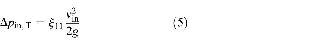
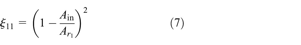
In the literature,20–22 we find a notable divergence between the results of theoretical calculations and the experimental data for bladeless turbine efficiency. This is because most researchers have not considered the loss caused by the working medium entering and flowing out of the turbine cavity when analysing the internal flow within the turbine. Figure 1(a) shows the simple cross-sectional view of the entrance when the working medium enters the turbine. The cross-sectional area of the flow channel expands suddenly as the fluid enters the turbine, and shock loss occurs when the fluid impacts the edge of the disk. However, as the thickness of disk is small, shock loss can be neglected in the actual analysis. Therefore, local expansion loss becomes the major contributor when the working medium enters the turbine cavity.

Schematic diagram of working medium entering or exiting the disks: (a) cross-sectional view of the entrance and (b) cross-sectional view of the exit.
Figure 1(b) shows the simple cross-sectional view of the exit. When the working medium flows out of the disks, the flow state changes dramatically, thus causing a large number of partial losses. At the same time, a massive shock loss is produced when the fluid impacts the edge of the disk. These two mechanisms are the major loss sources when the working medium flows out and can be calculated according to the principle of conservation of energy. Bearing loss can also degrade the operating performance of the turbine, so we should avoid it as much as possible in the design and machining process


where
where p is the pressure of the working medium at a point on the disk,
Experimental process and analysis
In this section, changes in the performance parameters of the bladeless turbine when using an incompressible working medium are discussed. First, a bladeless turbine is designed and manufactured for experimental use; then, the experimental data are analysed one by one, and the flow situation within the turbine is analysed by numerical simulation. Subsequently, the theoretical result is compared with the numerical simulation result. Finally, the conversion factors for the performance parameters of the bladeless turbine using an incompressible working medium and the majority of the turbine energy loss are obtained by analysis.
Experimental equipment
The main components of the experimental system are the bladeless turbine, torque sensor, display, torque generator, flow-meter, pressure gauge and other auxiliary equipment, as shown in Figure 3. The bladeless turbine is primarily composed of a smooth disk, spindle, bearing, shell and other parts. The assembly drawing and a picture of this turbine are shown in Figure 3(c) and Figure 3(d), respectively. The rotor is mainly composed of the shaft and disk, between which a gasket is introduced to ensure the design width and is fixed on the shaft by screws at both ends. A cross-sectional view of the bladeless turbine is shown in Figure 2, and the parameters are shown in Table 1.
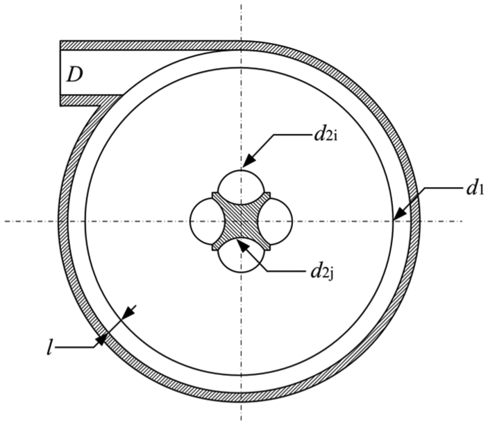
Schematic diagram of cross-sectional view of the turbine.
Design parameters of bladeless turbine.

Figure 3(a) and (b) shows the simplified diagram of the experimental system. The working medium flows through an electromagnetic flow-meter into the bladeless turbine on a tangent, where it dilates in the cavity of the turbine, thereby decreasing the inner pressure. The viscous force of the fluid then drives the disk to rotate, and finally, the fluid flows out from the turbine. A pressure gauge is installed before the turbine inlet, which protects against the disturbance produced by the working medium when it enters the turbine. The precision of the pressure gauge is chosen to be 0.02 MPa. As shown in Figure 3(b), the bladeless turbine (1) and torque sensor (2) should be on the same axis. The torque generator (3) is composed of nuts and threaded stents, in which the axes of the two threaded holes, torque sensor and bladeless turbine are positioned in the same horizontal plane and are vertically aligned with the axis of the turbine, thus ensuring that the torque direction imposed by the nut coincides with the axial direction of the turbine to reduce the experimental error. The instrument display (4) is connected to the torque sensor by wires, so it can directly show the output shaft power, rotational speed and torque of the bladeless turbine. The precision of the display for torque and rotational speed are 0.0001 N m and 0.01 r/min, respectively. The uncertainty analysis of components is shown in Appendix 2. To observe how the inlet velocity and pressure of the working medium affect the performance of the turbine during the experiment, the inlet conditions such as the inlet valve opening of the turbine and the outlet valve opening of the pump were changed. To observe how torque and rotational speed affect performance, the rotary depth of the nut on the torque generator was controlled to change the output torque of the turbine and the rotor speed, and the rotary depth of the nuts on both ends was kept at the same level throughout the experiment.

Schematic diagram of a Tesla bladeless turbine: (a) and (b) are the simplified diagram of the experimental system, (c) is the test bed of turbine, and (d) is the bladeless turbine.
Experimental data and analysis
When the experiment system begins to run, the inlet pressure of the working medium may be disturbed, which will affect the results of the experiment. Therefore, the system was run for a period before beginning the formal experiment to ensure that the experiment begins after the meter data become stable. During the experiment, the flow of water and the rotary depth of the nut were changed, and the readings on the torque gauge, pressure gauge and flow-meter were recorded and analysed one by one.
The relationship between rotor speed and experiment efficiency under different inlet pressure conditions is shown in Figure 4. Under the various pressure conditions, the data points are concentrated to some degree and present a certain regularity. Namely, as the rotor speed increases, the turbine efficiency initially increases, but after reaching a maximum, the efficiency starts to decrease. The parabola created by a quadratic fit can be used to reflect the relationship between the turbine rotor speed and efficiency well. In other words, under a certain inlet pressure, there exists an optimal speed that can maximize the operational efficiency of the bladeless turbine and ensure it works at the optimal condition. In addition, the turbine can reach different maximum speeds at different inlet pressures: a higher maximum rotor speed corresponds to a higher inlet pressure. An important factor in this relationship is that the working medium has a higher rotational speed after entering the flow channel between disks, which causes the working medium between disks to have a higher velocity gradient. As a result, the disk rotational speed increases as the disk shear stress increases. Moreover, the theoretical analysis in section ‘Output power and operation efficiency’ indicates that efficiency is directly proportional to power when flow and pressure head are constant. Similar to efficiency, the relationship between rotor speed and power of the turbine shows a parabolic trend.
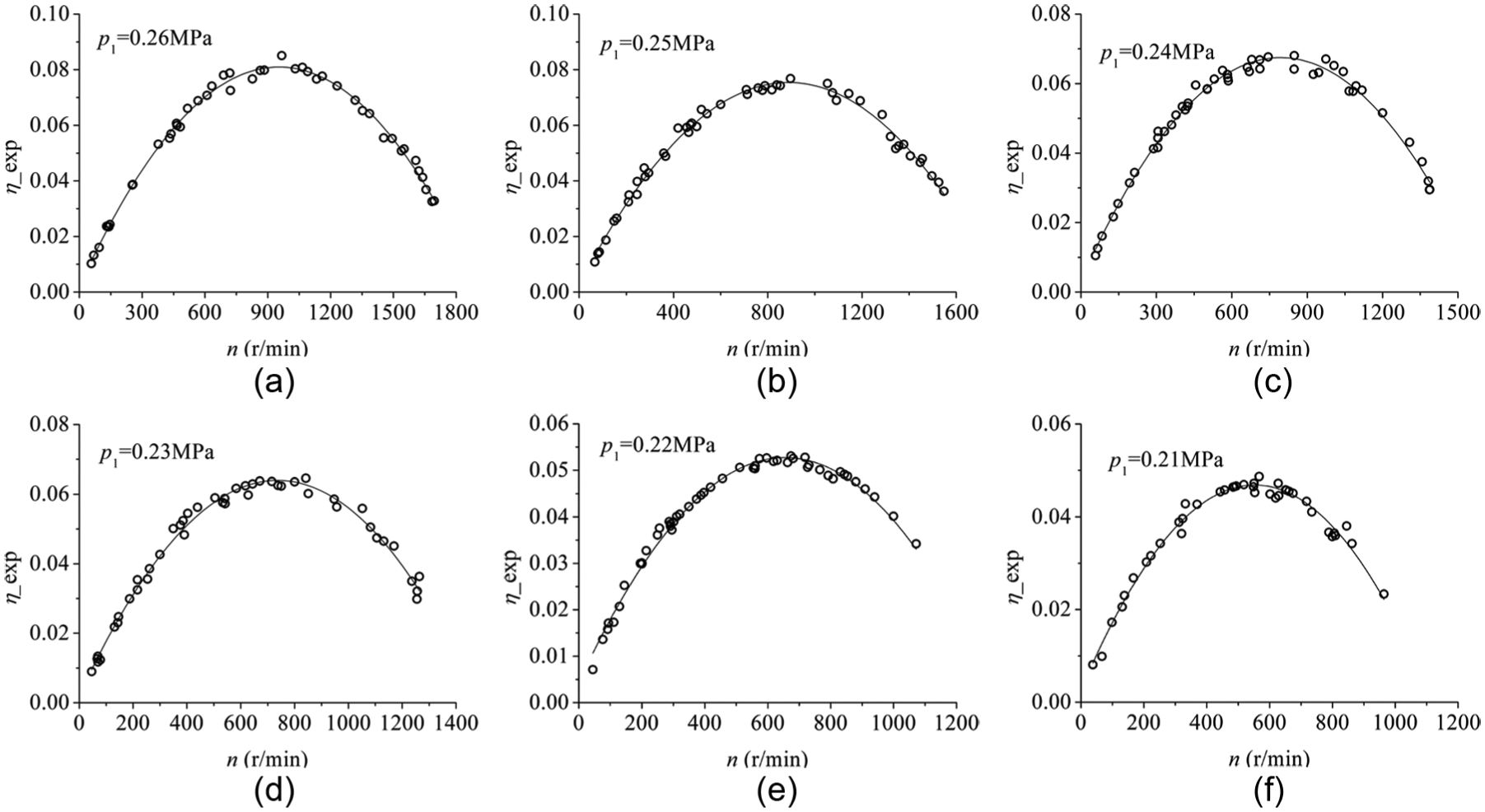
Relationship between rotor speed and efficiency of bladeless turbine under different inlet pressure conditions: (a) Q = 0.39 kg/s, (b) Q = 0.385 kg/s, (c) Q = 0.379 kg/s, (d) Q = 0.364 kg/s, (e) Q = 0.355 kg/s and (f) Q = 0.328 kg/s.
To observe the correlation between rotational speed and efficiency of the bladeless turbine under different inlet pressure conditions more clearly, all of the fitting curves are drawn on one figure, as shown in Figure 5, and the coefficients of each curve are listed in Table 3 of Appendix 3. In Table 3 of Appendix 3, ‘a’ is the quadratic coefficient, ‘b’ is the monomial coefficient and ‘c’ is a constant. It can be seen in Figure 5 that the efficiency of the bladeless turbine increases with the inlet pressure at a constant rotor speed, and that the fitting curves are close to each other at low speed, which means that the change in efficiency is imperceptible as the pressure varies. When the rotor speed exceeds the optimal speed, the change in efficiency increases with the pressure variation, which means that the inlet pressure has a marked influence on the efficiency of the bladeless turbine. While the turbine efficiency remains constant, adjacent curves have little difference at low rotational speed, which means that the influence of the pressure on the rotor speed is not obvious; however, the difference between curves increases at high speed, indicating that the influence of inlet pressure is prominent. Similarly, we can obtain the correlation between rotational speed and efficiency under varying input power. In addition, the rotor may be damaged when operating at very high speed, so it is better not to let the rotational speed of the turbine exceed the speed of peak efficiency (the optimal speed) to ensure that the rotor continues to work.

Schematic diagram of fitting curve.
Figure 6(a) shows the data fitting curve for turbine efficiency and torque under a given inlet pressure. There exists an optimal torque that can maximize the efficiency of the turbine as the relationship between efficiency and torque takes the form of a parabola. That operating point is the optimal point for the operation of the bladeless turbine. The torque cannot be too high or too low for the turbine to exhibit high efficiency in actual operation. Similarly, there is an optimal torque that can maximize the power of the turbine. To guarantee the service reliability of rotor, it is better to choose the working torque condition before the optimal operation point.

(a) Experimental fitting curve of torque and efficiency when the inlet pressure is 0.26 MPa and (b) experimental fitting curve of torque and efficiency under different inlet pressure conditions.
Figure 6(b) shows the data fitting curve of efficiency and torque under different inlet pressure conditions. The coefficients of each curve are listed in Table 4 (Appendix 3). Although a lower inlet pressure obtains higher efficiency at low torque, the turbine runs more efficiently at higher pressure as the torque increases and exceeds a certain value (intersection point of fitting curve). Combined with the conclusion drawn from Figure 6(a), the turbine should work below the points of higher inlet pressure and before the optimal torque to obtain higher efficiency.
Tan et al. 26 conducted the actual performance analysis and optimization for bladeless turbine and observed that the efficiency of the turbine can be achieved to 10.7%. This value closes to the maximum experimental efficiency obtained in our article. In Figure 6(b), the relationship of torque and inlet pressure is divided into three parts to investigate when the efficiency of the turbine is constant: in part A, the output torque of the turbine increases with the increase in the inlet pressure; in part B, the relationship between them is completely opposite and in part C, the relationship is identical to that in part A.
Figure 7(a) shows the torque and rotor speed under a constant pressure conditions. The rotor speed decreases linearly as the torque increases. Based on this correlation, the measured parameter can be calculated from the known parameter, which could simplify the process of data measurement in practical engineering and experimental studies. The torque and rotational speed data at different pressures are processed by linear fitting. All of the coefficients are listed in Table 5 (Appendix 3): k is the monomial coefficient, and c is the constant. From Table 5, we can see that the constant decreases as the pressure decreases but that the monomial coefficient generally shows an increasing trend. With a change in torque, the rotational speed under low pressure does not change as much as it does under high pressure. Figure 7(b) shows the fitting curves for experimental and theoretical efficiencies at different rotational speeds. The theoretical efficiency varies in parabolic form and is higher than the experimental efficiency. This is mainly because in the calculation of theoretical efficiency, the bearing loss, the shock loss caused by the impact of fluid against the disks at the entry and the flow loss within the turbine are not considered. There is a small gap between theoretical efficiency curve and the experimental efficiency curve at low rotor speeds, which means that the losses within the turbine are mainly the partial inlet loss and outlet loss. In the middle of the efficiency curve, the main reason for the large gap between the theoretical and experimental data is that the flow loss within the turbine is larger near the peak efficiency, which is not considered when calculating the theoretical efficiency. Thus, the theoretical analysis can be used to find the maximum efficiency of bladeless turbine without considering the bearing losses. In addition, it can also be employed to predict the inlet and outlet losses.

(a) Experimental data graph of torque and rotor speed when the inlet pressure is 0.26 MPa; (b) diagram of experimental fitting curve and theoretical calculation curve and (c) change in inlet and outlet losses with rotor speed.
Figure 7(c) shows how the curves of the theoretical partial inlet loss and the output loss change with the angular velocity under a pressure of 0.26 MPa and with a flow rate of 0.39 kg/s. As the angular velocity changes, the inlet local loss stays constant, while the output loss has a parabolic shape and is larger than the input loss. Therefore, reducing the output loss can significantly improve the efficiency of the turbine when using an incompressible working medium.
The points of highest efficiency points at different pressure and flow conditions (the edge rotating speed of rotor and inlet flow velocity of the fluid at the optimal efficiency points) from Figure 4 are listed in Table 2. As the inlet pressure decreases, Δv increases gradually, and the optimum efficiency of turbine decreases. Higher efficiency could be achieved when the speed of disk edge approaches the flow velocity of the working medium. It is mainly because that the degree of disturbance of fluid decreases as the decreasing in relative velocity (Δv: difference in speed between fluid and the rotor speed), resulting in the reducing of flow loss and increasing in efficiency. However, there is no velocity gradient on the surface of the disk while Δv is equal to 0, resulting in the disappearing of torque.
Rotational speed of disk edge and inlet flow velocity of fluid.

Numerical simulation and analysis
The experiment in section ‘Experimental data and analysis’ indicates that the turbine efficiency is lower when the working medium is water, which limits the industrial application of the turbine. Thus, in this section, the flow situation within the turbine and the generating mechanism of flow loss are studied by numerical simulation to provide a theoretical basis for performance enhancement of the turbine in the future.27–30
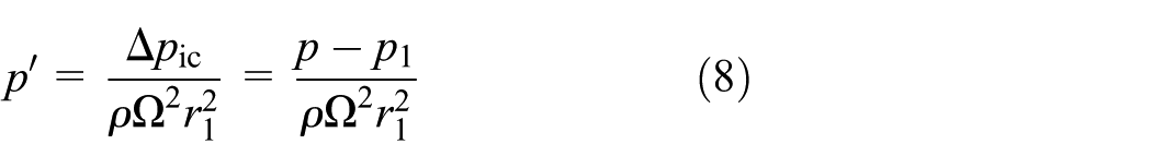
In section ‘Experimental data and analysis’, the theoretical and experimental efficiency of the turbine are calculated and analysed based on the assumption that the outlet pressure is atmospheric pressure, which cannot be used to improve and optimize the turbine in the future. However, we can analyse the causes of turbine loss more accurately and discover the utilization degree of fluid energy if we replace atmospheric pressure with the actual outlet pressure of the turbine to calculate its efficiency

where
We modelled the experimental turbine in 3D form and divided the grid, input the divided grid into the numerical simulation software and simulated it using a k–ε model. Mesh independence for the Tesla turbine has been conducted, and the results show that the performances of this bladeless turbine remain almost constant when mesh number is greater than 4,500,000. The ‘pressure-based’ solver with the sequential solving of the governing equations as well as the SIMPLE algorithm for correction of pressure and velocity is applied.31,32 So the mesh model of Case 3 is adopted in this article, and the results are independent of the mesh number.
Figure 8 shows the change in efficiency based on atmospheric pressure and obtained from numerical simulation and from experiment for varying rotor speed when the inlet pressure is 0.26 MPa. The changes in efficiency from simulation and from the experiment (

Comparison of turbine efficiency between simulation and experiment.
Figure 9 shows how the curve of turbine efficiency

Figure 10(a) shows how flow parameters vary with the turbine inlet distance when the rotating speed is 950 r/min. In Figure 10(a), the turbine inlet is at the right side, and the elliptical area shows the junction of the inlet and cavity. It can be noted that the total and static pressures sharply decrease when fluid enters the disk from the inlet and, simultaneously, that the flow velocity of the working medium increases gradually. Thus, the working medium loss at the entrance of the turbine is mainly caused by the decrease in static pressure. Figure 10(b) shows how flow parameters within the disk vary with changing radial distance. In this figure, the inlet parameters are identical with those in Figure 10(a), the flow velocity of the working medium presents less variation, and the total and static pressures decrease with declining radial distance. The output energy of the bladeless turbine rotor comes mainly from the pressure drop; the flow velocity curve fluctuates (0.0025–0.01 m) significantly at the outlet channel, thus causing part of the energy loss. In addition, the elliptical area in Figure 10(b) is the junction of the disk diameter and the outlet channel, where we find that although the flow velocity of working medium reduces sharply, the static pressure does not change dramatically. The variation of flow velocity and pressure lead to the loss in the disk entrance, and the former is the main factor. Figure 10(c) shows the contours of the turbulent kinetic energy and velocity vector, while the working medium flows from the outlet channel of the disk to the turbine exit; only 1–7 disk outlets are shown in this figure. When the working medium is in the turbine exit, it could form a back-flow that would result in a flow eddy. Moreover, the turbulent kinetic energy of the working medium is higher at the exit channel, and the flow velocity changes sharply, which causes massive flow loss. It can be noted from changes in the velocity vector arrow that the working medium at 2–5 disk outlets does not flow to the exit, which causes back-flow within the disks and reduces the operating efficiency of the turbine.
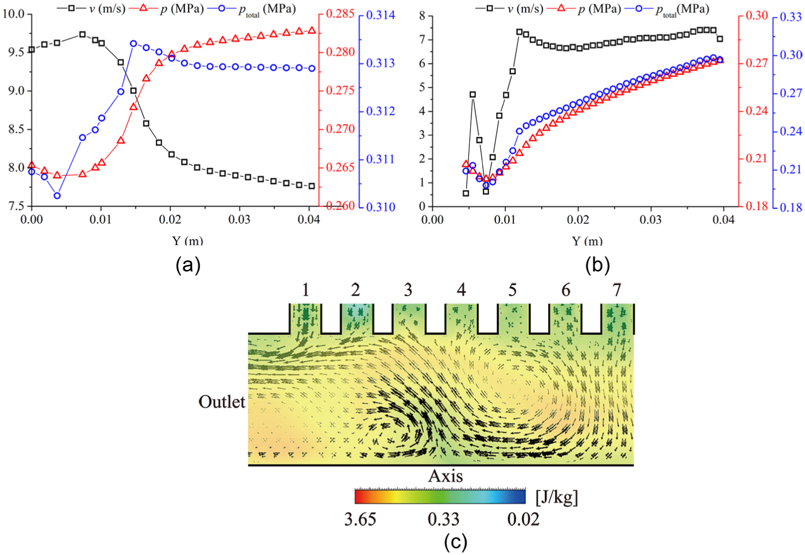
Q = 0.26 kg/s, n = 950 r/min: (a) pressure and flow rate at the inlet of the turbine; (b) internal pressure and flow rate of the disk and (c) outlet turbulent kinetic energy and velocity vector diagram.
Conclusion
This article studied the operating characteristics of a bladeless turbine by setting up a bladeless turbine experimental platform and developed a mathematical model corresponding to the entry and exit partial loss inside the bladeless turbine. Numerical simulation methods were used to further investigate the main causes of loss inside the turbine. The article could be employed to experimental studies in the future. Through the above analysis, the following conclusions were made:
The variation of efficiency with rotational speed is quadratic when the entry parameters remain constant. There is an optimum rotational speed and torque to maximize the efficiency of the turbine.
The variation of rotational speed with output torque of the bladeless turbine is linear. Output torque decreases as the rotational speed increases. The rotational speed has a significant impact on exit partial loss but little effect on entry partial loss. The variation of exit partial loss with rotational speed is quadratic.
The disk speed
Footnotes
Appendix 1
Appendix 2
The method of measurement uncertainty determination described in Jacobs 33 and Coleman and Steele 34 was adopted. Thus, the uncertainty determination of components can be obtained as following:
where
Appendix 3
Curve fit for torque and rotation speed.

| p 1 (MPa) | k | c |
|---|---|---|
| 0.26 | −18201.37515 | 1869.82678 |
| 0.25 | −18263.57701 | 1735.89926 |
| 0.24 | −18053.10887 | 1536.32588 |
| 0.23 | −18762.18618 | 1466.77617 |
| 0.22 | −17611.18104 | 1238.63565 |
| 0.21 | −16802.56188 | 1054.84969 |
| 0.2 | −16751.85009 | 822.60994 |
Academic Editor: Takahiro Tsukahara
Declaration of conflicting interests
The author(s) declared no potential conflicts of interest with respect to the research, authorship, and/or publication of this article.
Funding
The author(s) disclosed receipt of the following financial support for the research, authorship, and/or publication of this article: The authors are grateful to the support given by the National Natural Science Foundation of China (51676151).