
Abstract
Damage-scattering signal extraction using conventional ultrasonic guided wave–based damage detection techniques requires the measurement of baseline data under pristine condition. This study proposes a baseline-free ultrasonic guided wave damage localization and imaging method based on Lamb wave baseline-free probability imaging method. Although traditional Lamb wave probability imaging can monitor damage location in plate-like structures, the absolute time of arrival and magnitude of the signal are affected by several factors and are therefore difficult to obtain. This study also proposes a probability-based hyperbola diagnostic imaging method that is based on different times of arrival and has no magnitude information. A distributed active sensor network conforming to a pulse-echo configuration and time window functions is developed to separate damage-scattering signals from structural response signals. Continuous wavelet transform is used to calculate the time of flight of damage signal waves. The numerical simulation and experiments validate the effectiveness of the proposed method in identifying damage.
Introduction
The plate-like structure is a widely used type of structure in mechanical engineering, civil engineering, aerospace engineering, and some other fields. During the fabrication process, plate-like structure specimens inevitably display initial defects (such as cracks, holes, and delamination). 1 During the service process, the performance of the material degrades and the minor defects of the components would expand due to environmental corrosion, temperature change, external vibration, and other factors. Over time, both internal and external factors will diminish the overall performance of plate-like structures, which would result in varying degrees of damage with possibility of failure under extreme conditions. Due to its superior characteristics, the Lamb wave has been widely used in non-destructive testing of plate-like structures. Compared with the traditional detection methods (eddy current testing, X-ray, ultrasonic, and infrared imaging), Lamb wave–based non-destructive testing technology has a higher propagation speed, less energy attenuation, and a larger detection area in the structure, 2 which could greatly reduce detection time and improve detection efficiency. Besides these advantages, this technology can not only detect the internal defect of components but also the surface defect.
In recent years, the numerical simulation has been treated as an effective method to study the characteristics of wave propagation by many scholars. Actually, finite element method (FEM) is one of the most popular and accurate numerical calculation methods and has been used in many engineering and science areas. The simulation of ultrasonic guided waves has been carried out to monitor structure health. Moser et al. 3 simulated ultrasonic waves in annular structure using ANSYS. Shen et al. 4 modeled the propagation of shear horizontal (SH) guided waves in the circumferential direction of pipeline with three-dimensional (3D) solid element through ABAQUS. At the meantime, some new methods come into being. Yang et al. 5 used B-spline wavelet on the interval (BSWI) FEM and general shell theory to do the vibration analysis of curved shell. Pahlavan et al. 6 employed a wavelet-based spectral FEM to linear transient dynamics and elastic wave propagation problems. Hong et al. 7 investigated dynamics and waves characteristics in the functionally graded material (FGM) axial bars using spectral element method. In this article, ABAQUS is used to simulate ultrasonic waves in plate-like structure.
The typical Lamb wave detection technology is used to identify damage by comparing the data collected in the current state with that in the healthy state of a structure. However, this detection method could produce significant errors when compared with the baseline data because of the differences in the external environment and the operating conditions.8–10 Therefore, disregarding the original data and achieving baseline-free damage identification have become key trends in the development of the Lamb wave health detection technology. Kim and Sohn 11 extracted the damage signal generated from Lamb wave mode transformation by sticking piezoelectric ceramic pieces symmetrically on the upper and lower surfaces of an aluminum plate depending on the polarization characteristics of the piezoelectric materials and the reciprocity of wave propagation. Instantaneous baseline-free damage identification is performed by comparing the obtained values to an established damage threshold. Wang and Yuan 12 used an incentive-echo sensor network model to collect signal. In their study, time window functions are applied to intercept the amplitude characteristics of the damage signal, which achieves baseline-free damage signal extraction and attains damage identification using an imaging algorithm. Jeong et al. 13 utilized active sensor networks under incentive-receiving mode to collect signals and obtain structural response signal through time-reversal retrofocusing. This is proved to be an effective approach that could relieve the Lamb wave dispersion and signal-aliasing phenomenon, and it allows the wave packet of the damage-scattering signal to be shown independently.
To enhance the feasibility of the damage detection method based on Lamb wave, several scholars have proposed a method of damage probability imaging (including damage index method and time of arrival), which reduces the use of sensors and attains rapid damage monitoring. The imaging method of damage probability can image using the damage factors of each channel instead of depending on the speed of signal propagation. Su and colleagues14–16 utilized the cumulative distribution function (CDF) to establish a quasi-circular trajectory probability imaging method. Wang et al. 17 used the CDF to establish an elliptic probability imaging method and applied the probability assumption to the damage location algorithm, which not only makes the image clearer and brighter but also makes the positioning results more reliable. Probability imaging damage factor technology is a probability imaging method used to calculate the degree of damage on each sensor path by drawing the gray image of the probability of damage on each sensing path, fusing all the gray images of the sensing path, and achieving structural damage imaging. Most methods of calculating the damage factor are based on the damage factor of the signal energy and signal correlation. Although it does need analytical explanation for signal based on the damage probability imaging of damage index, the technology can only locate the clear damage in the sensor area. The damage probability imaging technique can detect damage to any location within the monitoring area based on time of arrival. However, due to the complex dispersion characteristics of the Lamb wave, the arrival time of the signal is difficult to obtain. Moreover, the difference between the piezoelectric transducer (PZT) sensors and the adhesive layer exists and could influence the difficulty. The difference would result in the difference in the signal amplitudes corresponding to the first wave collected by different receiving points with the same distance to the actuated point. Thus, an error between the amplitude of the damage-scattering signal and the real value is generated, which eventually influences the positioning imaging accuracy. Nevertheless, the arrival time of the signal is a sound signal characteristic, which would not be affected by the above factors. According to the time characteristics of the damage signal, a new algorithm of hyperbolic curve probability imaging is developed in this study, in which the absolute time of wave arrival is not needed.
Principle for hyperbolic curve probability imaging
In the process of probability imaging, field values at pixels can be calculated using various signal features extracted from captured signals, such as time of flight (ToF) and signal magnitude. In the experiment of damage imaging, signal magnitude is influenced by the bond condition between the sensors and the structure, which may reduce the location precision. However, the relative ToF is a robust feature of wave signals. Based on the preceding analysis, a probability-based hyperbola diagnostic imaging using relative ToF is proposed in this study. The schematic of the probability-based diagnostic imaging is shown in Figure 1.

Schematic of probability-based diagnostic imaging.
The set of points in a plane whose distances to two fixed points (

where
The aluminum plate model is assumed to be evenly divided into m*n nodes, each of which corresponds to the pixel point of the probability imaging.


The case
In this approach, a CDF
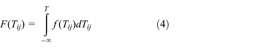
where

Time feature extraction of damage signal
Damage-scattering signal interception
Sensor networks of motivation-echo model are adopted to obtain structural damage signal in this study. 12 The plate could be divided into several regions when its size is very large (Figure 2). PZT sensors are located around each region which is known as PZT sensor arrays. PZT sensors in each array consist of basic monitor element so as to detect the damage in each corresponding region. The size of each region is usually determined based on minimization of detection radius 19 to optimize the location of PZT sensor. Sensor networks of motivation-echo model are applied to directly separate the direct signal, scattered wave signal in the inner region, and reflected wave signal on the boundary. In the experiments, two PZT sensors, one of which is used to motivate signal while the other one is to receive signal, are arranged on each detection point of the plate. During the signal activation/collection period, each PZT sensor would only collect the signal that is activated by the sensor located at the same detection point, while all the other PZT sensors would not participate in this process, which means that all the other PZT sensors would not activate/receive signals when one pair of the dual sensors is being tested, but all the dual sensors would be traversed each by each of this process. The distance between the activation element and collection element is so short that the direct propagation signal would be limited during the initial period of detection. While there still exists some distance for the other signals such as scattered wave signal and reflected signal to arrive at collection element, and the distance is nearly two times the distance between scatter and the transducer. Due to the increment of propagation distance, which results in the increment of propagation time difference between the direct propagated signal and the inner scatter signal. However, due to the disturbance of reflection signal on the boundary when the detection region is near the boundary, it is not reliable to detect damage with Lamb signal. The sensors distribution array is shown as Figure 2 boundary area layout, and the reflection signal and direct propagation signal would overlap at the beginning of damage detection period, while the direct propagation signal from the activation sensor would be eliminated so as to realize the detection of damage.

Active sensor network configurations.
According to the spatial location relationship of the sensors, the direct waveform is first received by

Typical Lamb wave structural response signal.
In the study of Lamb wave phased array structural damage monitoring, due to the different distances between each pair of actuator and sensor, the propagation time of direct wave in each response signal is different. Besides, the end time of the direct wave in each response signal is also different because of the time delay. Sun et al. 20 proposed the method of dynamic window function to intercept the signal of damage. The rectangular window function is convenient and it is used in this study. The start and end time of the rectangular window function would correspond to the end time of direct wave signal and the beginning time of reflection wave signal of structure boundary, respectively. The distance between the sensors and the distance between the sensor and the boundary will be determined after the sensor network array is arranged. The end time of a rectangular window function is calculated by the boundary that is nearest to the pair of sensors. Thus, the rectangular window function is 12

where
Relative time extraction of wave arrival
The continuous wavelet transform, which has a high-frequency resolution and a low time resolution in low-frequency part and a high time resolution and a low-frequency resolution in high-frequency part, is an effective method to extract the time–frequency information of time series. The basic principles are given below. 21
Supposing,


where
The continuous wavelet transform is used for the time–frequency analysis of structural damage signals in this study. The time corresponding to the maximum value of energy in the time–frequency analysis diagram is selected as the arrival time of the damage signal, and the time corresponding to the maximum energy value received by two sensors would be subtracted to acquire the
Numerical simulation
The finite element software ABAQUS is used to simulate the hyperbolic probability imaging algorithm, and the aluminum plate used in this study is selected as the simulation object. The display dynamic analysis program of ABAQUS/Explicit is realized using the explicit integration rule of the diagonal mass matrix. The equations of motion based on explicit central difference integration rules are shown in equations (10) and (11)


where u is the displacement or rotational component and

where
The element size of the plate depends on the minimum wavelength and usually 20 nodes are taken in a minimum wavelength. So the cell size is 3

where
The size of the aluminum plate is 1000 mm × 1000 mm × 4 mm. The material properties of the aluminum plate are illustrated as follows: elastic modulus E is 71 GPa and Poisson’ ratio v is 0.33, and density ρ is 2700 kg/m3. Entity unit C3D8R is adopted to complete structured mesh division.
The features of the aluminum plate are as follows: a 20-mm-diameter circle through as the damage source is dug on the aluminum plate surface, with the center of the circle located at (470 mm, 550 mm). Rayleigh damping is not taken into consideration and the boundaries are free in this simulation. A single A0 mode with 40 kHz center frequency as the incident wave is motivated via an anti-symmetry load excitation method to detect the damage. Since the piezoelectric element C3D8E does not exist in ABAQUS/explicit, 16 self-equilibrating concentrated forces are applied to simulate the wave excitation for the round PZT actuators. Specifically, the mode A0 will be excited when the 16 self-equilibrating concentrated forces are anti-symmetrically loaded on the top and the bottom of a plate.
The wave propagation velocity used in this simulation is determined by the dispersion curves of the aluminum plate in Figure 4. The wave velocity is chosen 2100 m/s based on the center frequency and the thickness of the plate at last.

The dispersion curves for a 4-mm-thick aluminum plate: (a) phase velocity dispersion curves and (b) group velocity dispersion curves.
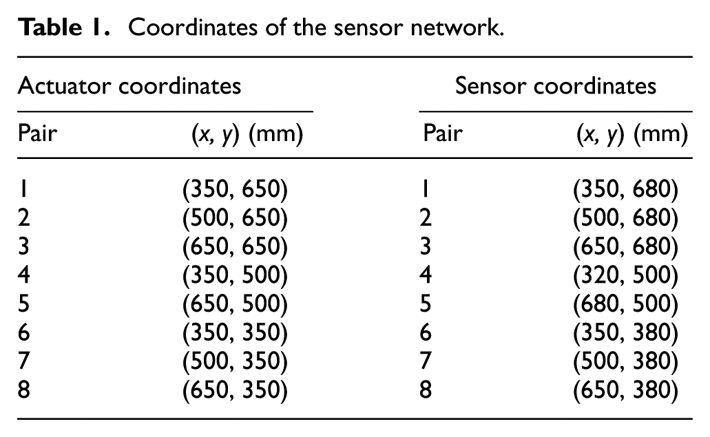
A distributed active sensing network is used; besides, the model and the sensing array layout are shown in Figure 5. The specific locations of the sensors are shown in Table 1. The response signal of the structure is shown in Figure 6. The rectangular time window function is adopted to intercept the damage-scattering signal, the result of which is shown in Figure 7. The result of the wavelet analysis of the damage-scattering signal is shown in Figure 8.

Active sensor network with a pulse-echo configuration.
Coordinates of the sensor network.

Structural response signal obtained by numerical simulation.

Damage-scattering signals obtained by numerical simulation.

Continuous wavelet transform of damage-scattering signal.
Two sensors can determine one branch of a hyperbola, which is shown in Figure 9. The collected signals from four and eight sensors are separately adopted to obtain positioning and imaging, and the hyperbolic probability imaging results are shown in Figure 10. As can be seen from the result, the more the number of sensors, the clearer the highlight area on the image. The probability location of the eight sensors is (467 mm, 552 mm), which is close to the damage location. Thus, the reliability of this method is high.

The damage localization of hyperbola probability imaging established by two sensors.

Probability-based hyperbola imaging results: (a) damage imaging result using four sensors and (b) damage imaging result using eight sensors.
Experimental verification
The set of equipment of function signal generator, power amplifier, digital oscilloscope, computer, aluminum plate, and piezoelectric ceramic chip is used to conduct a Lamb wave damage detection experiment. The sensor network of incentive-echo model is used to carry out experimental research on aluminum plate with damage. The algorithm feasibility is verified by this experiment.
If a damage exists in the structure, then the damage will be used as a second source to scatter the signal around by employing the Lamb wave to detect structural damage. The damage-scattering signal is received by the sensors, and then the damage location will be detected. The aluminum plate specifications and the layout of the sensor network are consistent with the numerical simulation, as shown in Figure 11.

An aluminum plate specimen with an active sensor network with a pulse-echo configuration.
A0 mode, with center frequency of 40 kHz, is adopted as the incident wave to test the damage of aluminum plate. Dual PZT actuators are mounted symmetrically on the top and bottom surfaces of the plate, and the frequencies of excitation signals are controlled to a range so as to generate the anti-symmetric mode A0 only. This mode selection technique can be expressed as follows: 22 when dual PZTs are out-phase energized, the anti-symmetric mode A0 would be generated to dominate the majority of wave energy, and the symmetric mode S0 is suppressed.
The structural response signals received by the sensors are shown in Figure 12. Since the signal consists of direct wave, damage-scattering wave, and boundary reflection wave, rectangular time window function is adopted to intercept the damage-scattering signal (Figure 13). Continuous wavelet transform is subsequently applied to the damage-scattering signal to extract the time characteristic, which is shown in Figure 14. The damage positioning and imaging of aluminum plate are carried out through the hyperbolic probability imaging algorithm. The probability imaging results from eight sensors are shown in Figure 15. The imaging is clear and bright, and the positioning results are accurate.

Structural response signals sensed by PZT array.

Separated damage scattered signals by time window function.

The continuous wavelet transform of damage scattered signal.

Damage probability–based imaging result.
Conclusion
To address the existing shortcomings that Lamb wave damage probability imaging needs the absolute wave arrival time or the amplitude of first wave, a hyperbolic baseline-free probability imaging method based on relative time difference is proposed in this study. Active sensor network of incentive-echo model and rectangular time window function are applied to generate structural damage signal; thus, the dependence on the structure of the baseline data is eliminated. Wavelet transform–based time–frequency analysis is adopted to extract the time corresponding to the maximum energy value for two different sensors according to hyperbolic positioning formula to calculate the damage probability of each point in the structure and realize the imaging and localization to the damage. The consistency of the numerical and experimental results shows that the method can be directly used to process the received Lamb wave signal in the current state, and thereby eliminating the dependence on the reference signal. This algorithm is proved to have good accuracy and precision to position structure and improves the practicability and stability of the Lamb wave damage localization technique.
Footnotes
Academic Editor: Jun Li
Declaration of conflicting interests
The author(s) declared no potential conflicts of interest with respect to the research, authorship, and/or publication of this article.
Funding
The author(s) disclosed receipt of the following financial support for the research, authorship, and/or publication of this article: The authors are grateful for the financial support from the National Natural Science Foundation of China (NSFC; grant nos 51278083 and 51478079) and the Fundamental Research Funds for the Central Universities (grant no. DUT15LAB11).