
Abstract
The key parameters which caused the scoring failure of helical gears are operating load and speed. In this study, the simulations using geometric meshing theory were carried out to investigate the effect of load and speed of warship transmission helical gear system on thermal elasto-hydrodynamic lubrication. The numerical algorithm for the analysis of three-dimensional thermal elasto-hydrodynamic lubrication used in this work has advantage that the film pressure and distributions can be calculated from Reynolds equation for all mixed lubrication regions without any specific boundary condition for the edge of solid contact region. Oil film pressure, film thickness as well as film temperature under different load and speed conditions were obtained and compared. In addition, experimental tests were conducted to determine gear surface temperature under different load and speed conditions. This work provided a guidance to understand the load- and speed-dependent thermal elasto-hydrodynamic lubrication.
Introduction
The wear caused by insufficient lubricant is the most general issue of endurance life troubles. The lubrication is mandatory to improve the endurance life of gears. As the primary failure modes, gear scoring is one type of adhesive wear caused by oil film breakdown. It usually occurs in a short time and could sometimes damage gear surface.1–3 To date, a great deal of studies 4 have been done to study teeth cracking and pitting due to scoring. Some empirical equations and criteria 5 were thereafter presented. In addition, some studies 6 have been conducted on effect of profile modification of gears on scuffing, while other studies 7 have been focused on presenting calculation method for gear scoring.
The study of lubrication has been advanced for past several decades. 8 A large number of theoretical discussions and experimental proofs helped to understand the lubrication mechanism. Especially, elasto-hydrodynamic lubrication (EHL) theory has been used for improving the life of machine elements such as bearing and gear surface. 9 Although there are vast studies concentrating on gear scoring, an accurate equation has not been developed because of the complicate factors which result in gear scoring.10,11
In order to understand the mechanism of gear scoring, detailed simulations using geometric meshing theory were performed to study effect of load and speed on thermal elasto-hydrodynamic lubrication (TEHL). Oil film pressure and film thickness as well as film temperature were compared under different load and speed conditions. Finally, experiments were carried out to validate simulation results.
Geometric meshing theory
A transmission (including one pair of tested gears and one pair of driving gears, as shown in Figure 1) is investigated. It comprises an input shaft, upon which all the pinion gears are mounted. It utilizes two output shafts, chiefly in a quest to reduce the required package space. The driven gear pairs are mounted onto these output shafts in the configuration shown in Figure 1. The study reported corresponds to an engaged pair.
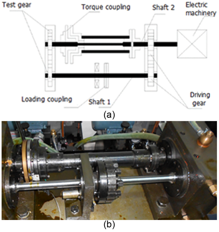
Schematic representation of (a) experimental setup and (b) real experimental setup.
The motion equation for this transmission with engaged gear pair is as follows,
12
where

where h is the screw parameter, θ is the surface parameter of the screw involute surface, ϕ is the angle of gear rotation, r is the radius of operating pitch cylinder (axode), o is the half of the angular width of the tooth space on the base circle of gear, n is the surface unit normal, l is the axial dimension of helical gear, and ρ is the pitch cylinder of radius.
Following equation (1), parameter

Submitting equation (2) into equation (1), the following equation is expressed14,15

Considering equations (1)–(3), the following equation is expressed, where

Following equations (3) and (4), the equation is rewritten as follows16–18

The tangential velocities for tooth flanks are effective. These velocities are variable along the action line of driving and driven gear wheels, the equation is as follows


where
Therefore, contact forces and conjunctional frictions are necessary to determine the overall dynamic response. In turn, meshing dynamics is essential to predict various prevailing tribological performances. The former is an essential refinement requirement for gear transmission system anti-scuffing properties, while the latter determines transmission efficiency and emission characteristics. However, these attributes can often lead to the degree which technical pragmatism should normally be exercised.
Experiment
Experimental setup
In this study, closed power flow (CPF) gear transmission test bed was used to conduct these tests. The CPF test bed is shown in Figure 1, which shows two helical gear pairs including one pair of tested gears and one pair of driving gears. Torque coupling is employed to obtain the torque load. A detachable lever is attached on the torque coupling, and then, static loads are applied on the lever to produce dynamic load. The product of the lever length and the dead load was the torque load on the helical gears. The design of test bed is ideal for our research; it can change helical gears’ load and speed easily to investigate their effects on EHL.
Using the developed test platform, two cases of EHL problem are evaluated: one is load and the other is speed. Experiments are conducted under three load and speed conditions, respectively, load: two levels (24 kg), four levels (48 kg), and six levels (72 kg) and speed: 200, 350, and 500 r/min.
Gears’ parameters
Tested gears’ basic parameters are presented in Table 1.
Parameters of tested gears.

Tested gears are made of SAE8620 steel, which has a hardness of 55 HRC. And, gear surface roughness is 1.6–3.2 µm for all tested gears. The material properties of tested gears have been presented in Table 2.
Material properties.

Lubricating oil
In this section, tested gears are lubricated using oil splashing method. The oil is heated until the temperature reached 90°C in an oil depot where the heater and thermostat are installed.
The lubricant flows into lubrication region at the velocity of 0.5 m/s from the nozzle to tested gears’ meshing point on their engaging side. Material properties of lubricant are presented in Table 3.
Material properties of lubricant.

Simulation results
Effect of load on EHL
According to the gear parameters shown, effects of load on oil film pressure, oil film thickness, and oil temperature are studied according to geometric meshing theory. Three loads at meshing point are calculated using these parameters. We have obtained the value of 628,620, 828,620, and 1,028,620 N/m, respectively, corresponding to dimensionless load of 4.50 × 10⁻⁵, 8.70 × 10⁻⁵, and 1.08 × 10⁻⁴. We compared oil film pressure, film thickness, and interface temperature under different loads, as shown in Figures 2–5.

Oil film pressure under different loads.

Oil film thickness under different loads.

Oil film mesospheric temperature under different loads.

Driving wheel interface temperature under different loads.
As shown in Figure 2, when the load is lower, pressure distribution is close to the results calculated by classical lubrication theory. In contrast, when the load is higher, pressure distribution is in a good agreement with Hertz pressure distribution. When decreasing the load level, the calculation results also show that the height of secondary pressure wave increases and their positions move to the inlet area. In Figure 3, we can see that the oil film thickness decreases with the increase in the load level, while the area of oil film inlet and outlet expands. In Figures 4 and 5, we can also see the same trend; oil film pressure, oil film center temperature, and interface temperature increase with increase in the load level. When the unit line load increases, the secondary pressure wave is small, and pressure distribution is close to Hertz pressure distribution. In order to ensure the results’ reliability, Hertz distribution (HD) and secondary pressure distribution (SPD) calculation results are compared in unit line load; maximum value is 1,028,620 N/m, as shown in Figures 6–9.
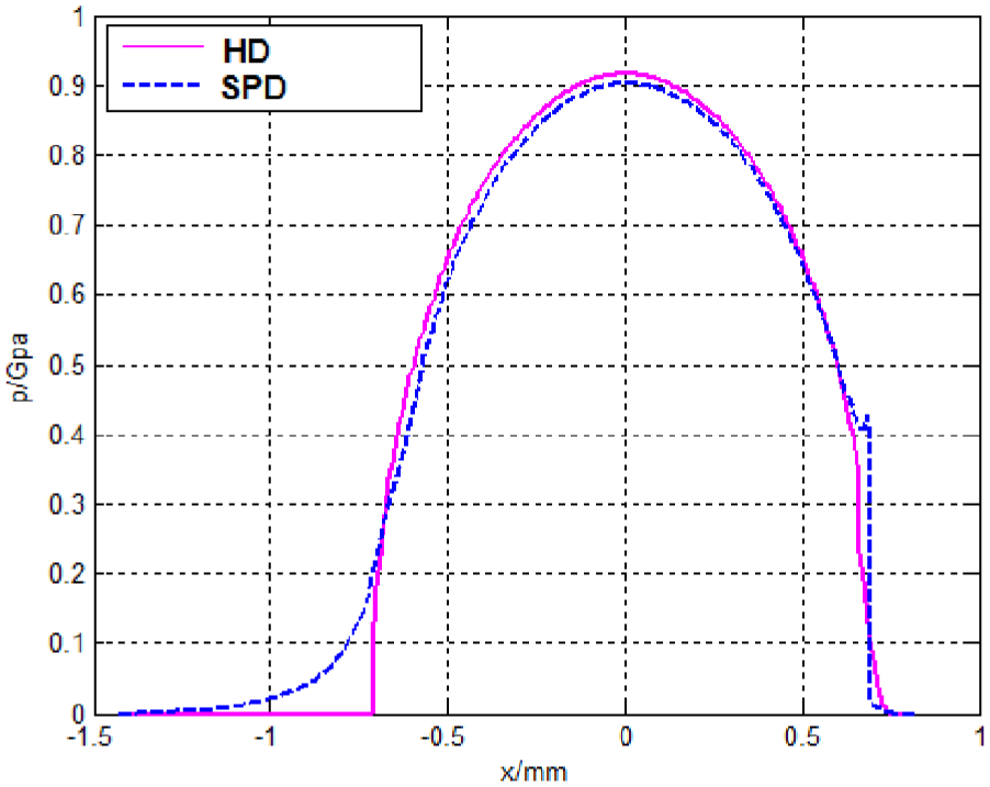
Oil film pressure using HD and SPD.

Oil film thickness using HD and SPD.
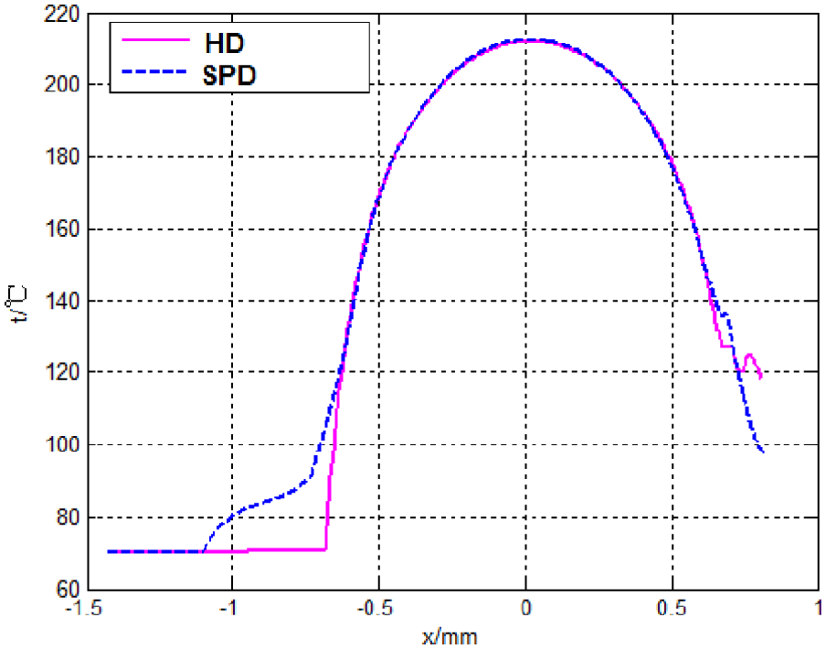
Oil film temperature using HD and SPD.

Interface temperature using HD and SPD.
These results can be explained by wedge effect of the EHL mechanisms. The viscosity of fluid greatly increases when fluid is suppressed in small contact region under the high applied pressure. HD and SPD calculations yield the similar results, especially for the temperature in oil film center. Therefore, the computation accuracy of the Hertz pressure distribution under heavy load is ignored.
Effect of speed on EHL
The speed of gear pairs’ meshing point greatly increases when fluid is suppressed in small contact region under the high applied pressure. The lubricant reaches the semisolid state like a viscoelastic substance. Comparisons of oil film pressure, thickness, and interface temperature under different speeds with 1000, 2000 and 3000 r/min are shown in Figures 10–13.
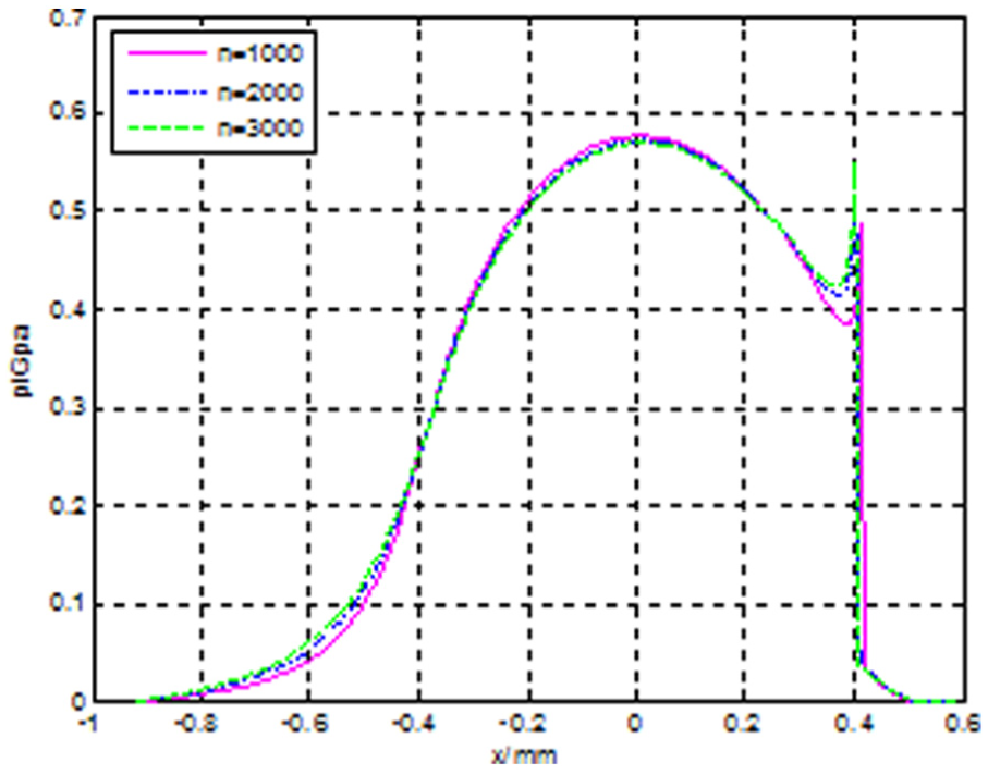
Oil film pressure under different speeds.
Oil film thickness under different speeds.

Mesospheric temperature under different speeds.
Interface temperature under different speeds.
According to the results above, the speed is like that a wedge is placed between oil film pressure and thickness. When the speed increases, the maximum oil film pressure decreases greatly. In contrast, the increase in oil film thickness results in a decrease in oil film parallel part. In addition, the height of secondary pressure increases and its position moves toward the inlet. Therefore, the oil film necking position moves toward the inlet direction, oil film pressure and film thickness are sensitive to the entrainment speed. Furthermore, oil film center temperature increases with the increase in the speed, and interface temperature decreases with the increase in speed. Although the speed makes locally the wedge effect, the direct contact between two solids can occur because the wedge effect is not so large to prevent the solid-to-solid contact. This phenomenon obviously appears in Figures 10–13.
Case study
In this section, two pairs of helical gears are used to investigate their EHL using the present method. The gears parameters are given in Tables 4 and 5. The material properties of the lubricant are shown in Table 3.
Parameters of first pair of tested gears.

Parameters of second pair of tested gears.

Thermal EHL theory is used here to obtain EHL of these two pairs of gears. The oil film thickness (oil film H) and oil film pressure (oil film P) distribution of the first pair of gears are shown in Figures 14–16.

Film pressure and thickness distributions.

Mesospheric and interface temperature.
Oil film temperature field distribution.
Conducting the first gear pair calculations, meshing unit line point load is 209,280 N/m, which results in the dimensionless load is 2.385 × 10⁻⁵, and the dimensionless velocity is 1.42 × 10⁻¹⁰. Maximum oil film pressure is 0.478 GPa, and minimum oil film thickness is 2.822 µm. In addition, driving wheel interface temperature is 75.2°C, and driven wheel interface temperature is 78.1°C. Maximum oil film temperature is 173.4°C. Oil film thickness (oil film H) and pressure (oil film P) distributions are shown in Figures 17–19.

Film pressure and thickness distributions.
Mesospheric and interface temperature.

Film temperature field distribution.
Conducting the second gear pair calculations, meshing unit line point load is 428,620 N/m, which results in the dimensionless load is 4.501 × 10⁻⁵, and the dimensionless velocity is 3.98 × 10⁻¹⁰. Maximum oil film pressure is 0.574 GPa. Minimum oil film thickness is 1.799 µm. Driving gear interface temperature is 81.4°C, and driven gear interface temperature is 80.05°C. Maximum oil film temperature is 163.7°C.
Experimental results and discussion
Experimental study on influence of load and speed for temperature
In this study, to analyze teeth surface, anti-scuffing properties influence degree on marine gear transmission system with differential load and speed. Different speed and load conditions versus teeth surface transient temperature measurement results are shown in Tables 6–8.
Two levels’ load condition and results.

Four levels’ load condition and results.

Six levels’ load condition and results.

These test data are shown in Figures 20–22.

Temperature under different loads: teeth surface temperature at (a) 200 r/min, (b) 350 r/min, and (c) 500 r/min.
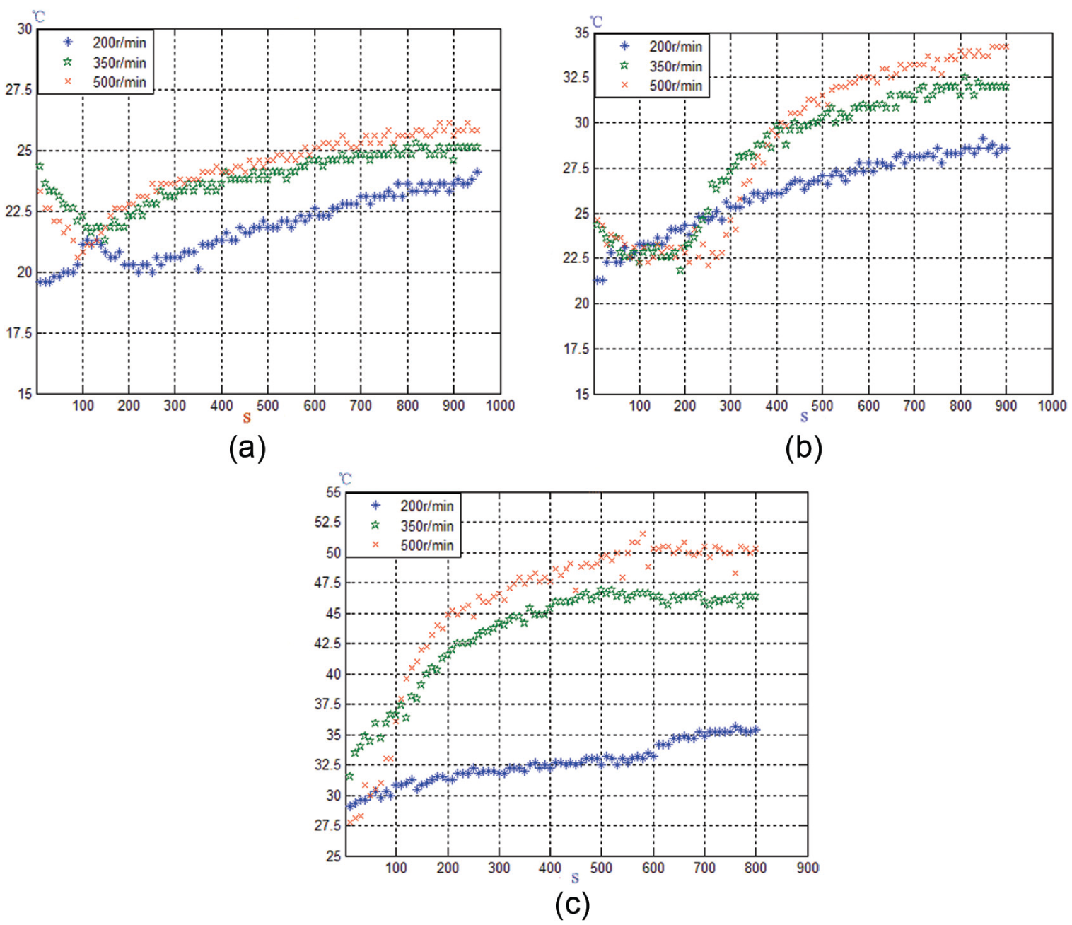
Temperature under different speeds: (a) two levels, (b) four levels, and (c) six levels.
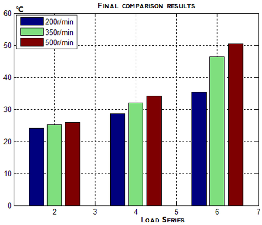
Teeth surface steady-state temperature under different speed and load conditions.
Analysis of experimental data
Before conducting teeth surface steady-state temperature analysis, the boundary conditions of the analysis are defined. This entails specifying the input speed and load (or power). Teeth surface temperature changes with the variation of load and speed. Under same load and speed, the temperature becomes stable with time because the heat amount produced and that dissipated become stable during helical gears are running.
Conclusion
Modern warship transmission engineering is concerned with efficiency, load, and speed. Progressively, TEHL analysis plays an important and an integral part of design and development. This constitutes development of CPF gear transmission EHL dynamic models, rather than the traditional gear pair models. Such a model is described in this article, comprising transient mixed TEHL dynamics of loaded gear teeth pairs as well as TEHL dynamics gear pair conjunctions. In this article, in order to investigate tooth surface anti-scuffing properties on gear meshing of marine transmission system, both simulation and experiments have been performed to study the effect under different load and speed conditions on EHL of gear pairs.
Footnotes
Academic Editor: ZW Zhong
Declaration of conflicting interests
The author(s) declared no potential conflicts of interest with respect to the research, authorship, and/or publication of this article.
Funding
The author(s) disclosed receipt of the following financial support for the research, authorship, and/or publication of this article: This work is supported by pre-research project in Ship Research Institute of China (grant number: MAPT 28062015). Part of simulation works were performed on Dawning-TC5000 system in Supercomputing Centre, Shenzhen Institutes of Advanced Technology, CAS, China.