
Abstract
High-speed punching presses are widely applied in modern manufacture industry, especially in occasions of automatic production with a large or a super large quality. To obtain a better production efficiency and a wilder application in industries, it is meaningful to develop the high-speed punching presses with a large press force and a long press stroke. Considering the limitations of mechanical and servo high-speed punching presses, hydraulic technology is the most possible way to develop the high-speed punching press with a large press force and a long press stroke so far. This article has proposed a hydraulic operating principle based on the hydraulic vibration technology for the development of the high-speed punching press with a press force of 1250 kN, a press stroke of 50 mm, and a press velocity of 1000 hpm. With a simulation model built under the AMESim environment, performances of the system are obtained and analyzed. Then, parameter optimization is also carried out and discussed. Finally, the operating principle and the parameters are refined. The obtained results have proved that the design meets the aimed performances of the high-speed punching press.
Introduction
High-speed punching presses are one of the important machines in modern manufacture industry. With the advantages of high product efficiency, high material utilizing rate, low machining cost, and good reproduction accuracy, they are widely applied in fields of electronics, telecommunication, motor, household appliances, and automobiles. At present, it is the most practical and feasible way to achieve the automatic production with a large or a super large quality.
Press force, press stroke, and press velocity are the three import indices to evaluate the performances of the high-speed press. Here, press force refers to the force acting on the workpiece during the press forming, press stroke refers to the displacement which the punching press can achieve, and press velocity refers to the number of press cycles that the punching press can achieve in a unit time, which is usually counted in a minute and obtain a unit of hits per minute (hpm). It is easy to understand that both a large press force and a fast press velocity have benefits to improve the production efficiency. For example, a large press force makes it possible to produce more workpieces in one press forming, while it is much evident in the relationship between the press velocity and the production efficiency. Meanwhile, a long press stroke is also important for the punching press. To some kind of machining workpiece, it needs a longer press stroke to complete the press forming. For example, a can may need a press stroke of 10–20 mm, while the silicon sheet only needs a press stroke of <1 mm. All in all, to obtain a better production efficiency and a wilder application in modern industries, it is meaningful to develop the high-speed punching presses with a large press force and a long press stroke.
According to the operation principles, the high-speed punching presses can be divided into three types: 1 mechanical ones, hydraulic ones, and servo ones. Considering the poor production flexibility and serious power loss, there are few new types of mechanical high-speed punching presses developed in recent years. Also, because of the limitations of servo motors, such as the small power capacity and the long response time under heavy load, 2 hydraulic technology is the most possible way to develop the high-speed punching presses with a large press force and a long press stroke so far.
Hydraulic high-speed punching press usually utilizes a main control valve to make the piston of a cylinder move in a reciprocation linear way. Researches are always focused on the performance improvements of the punching press, such as increasing press velocity, reducing power loss, suppressing vibration and noise. Brahmer 3 proposed a method with over-control position set points around the upper and lower dead points. Through this way, the openings of main control valve would be comparatively large, and the piston movement is carried out more quickly, especially in the area near the upper and lower dead points, which leads to a rapid press velocity. To reduce the noise and cavitation caused by cutting impact phenomenon, Brahmer 4 used a pressure-controlled throttle valve in the return flow line. Schaber 5 developed a multi-pressure operation principle to control the oil pressure based on the pressing stages, which could reduce the energy requirement considerably. What is more, a new-styled main control valve was proposed, which is a slide valve with a mechanical displacement feedback from the piston and is placed inside the piston. Ostini 6 invented an electro-hydraulic hybrid system for the high-speed punching presses. The main control valve of the system is a slide valve with the spool driven by the oil pressure, which is controlled by a small piston driven by a servo motor–cam system. This system has combined the powerful press force of hydraulics and the precision of electronic control at the same time. Essentially, the above control valves are servo valves and are always working at the middle position, which leads to a relatively high throttling power loss and a rapid temperature rise of the oil. Therefore, servo valves are not suitable for the development of the high-speed punching press with a great power, which will cause a severe problem of high oil temperature. To solve the problems caused by servo valves, Tang 7 proposed a two-stage pilot-operated cartridge valve for the main control valve. In this valve, two high-speed on-off valves first control a direction valve and then the direction valve controls a cartridge valve. It is hoped to combine the advantages of the high-speed on-off valve and the cartridge valve, in order to meet the need of the high-speed punching press with a great power. However, the service life of the cartridge valve will not be long enough in such a high frequency on-off working condition. And there is no report about the successful use of the valve until now. At the same time, other researches8–12 expected to solve the throttling power loss problems by the displacement-control systems. Considering the rather low operating frequency, they are obviously not working for the high-speed punching press.
As mentioned above, the authors choose the hydraulic vibration system as the operation principle of the high-speed punching press with a large press force and a long press stroke. Here, to describe briefly, the high-speed punching press refers to the high-speed punching press with a large press force and a long press stroke in the following part of this article. The hydraulic vibration system utilizes the fluid as the working medium, converts the pressure energy of the fluid to the kinetic energy of the piston, and outputs the energy with the vibration movement, which is very convenient to complete the high-speed punching movement. However, both the modelling difficulties of the hydraulic vibration system13–19 and the nonlinearities of hydraulics20–27 make it very hard to study the performances of such a hydraulic vibration system such as the high-speed punching press. To the best of authors’ knowledge, there is no report about this kind of research until now.
With the aim to develop a high-speed punching press with a press force of 1250 kN, a press stroke of 50 mm, and a press velocity of 1000 hpm, a hydraulic operating principle based on the hydraulic vibration technology is proposed first. Then, with the roughly determined parameters, a simulation model of the hydraulic system is built under the AMESim environment. Based on the analysis of performances, some optimizations are carried out. Finally, the operating principle and the parameters are refined. The obtained results have proved that the design meets the aimed performances.
Operating principle based on the hydraulic vibration technology
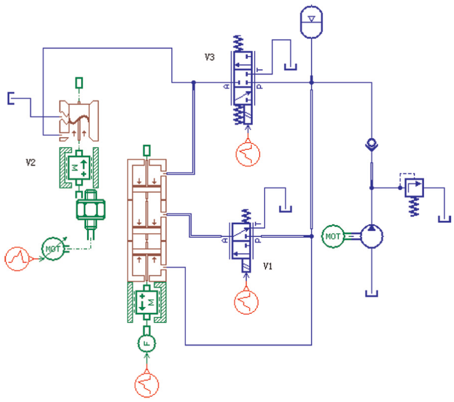
Based on the hydraulic vibration technology, the operating principle for the high-speed punching press is illustrated by the system shown in Figure 1. The features of this system are as follows:
A dual-pressure circuit is designed. The high pressure, Ps, is provided by the pump, and the low pressure, Pa, is provided by the accumulator. Here, since the pressure Ps is much higher than the pressure Pa, we assume the fluid pressure of the accumulator remains constant as Pa during the punching process.
A differential cylinder with three pressure chambers is designed. The three pressure chambers are labeled as CV1, CV2, and CV3. Here, CV3 keeps in connection to the pump.
Three control valves are utilized. Valve V1 controls the fluid flowing from the pump into CV2 or from CV2 into the tank, valve V2 controls the fluid flowing between the accumulator and CV1, and valve V3 controls the fluid flowing from the pump into CV1. In order to obtain a predesigned punching movement, the three control valves must operate according to a certain time sequence, which is carried out by the control unit.
A relief valve connects the accumulator to the tank.

Operating principle for the high-speed punching press.
A punching cycle can be divided into three stages: extending, punching, and retracting. Here, extending stage makes the piston move quickly from the upper dead point to the position very close to the workpiece, punching stage completes the press forming action, and retracting stage makes the piston return quickly from the lower dead point to the upper dead point. And the hydraulic schematic diagrams of the above three stages can be demonstrated in Figure 2 in detail:
Extending stage. Valves V1, V2, and V3 work at the lower position. Therefore, CV1 is connected to the accumulator, while CV2 is connected to the pump. Here, the cylinder works as a differential cylinder. With the high pressure acting on CV2 and CV3 and the gravity of the piston, the piston extends quickly toward the workpiece. The accumulator should provide enough fluid into CV1 to prevent the cavitation.
Punching stage. Valve V1 works at the lower position, while valves V2 and V3 work at the upper position. Then, CV1 and CV2 are connected to the pump, which makes the piston have the largest press force to punch the workpiece.
Retracting stage. Valve V1 works at the upper position, while valves V2 and V3 work at the lower position. Then, CV1 is connected to the accumulator, and CV2 is connected to the tank, which switches the movement direction of the piston under the high pressure in CV3.

Three stages of one punching cycle: (a) extending, (b) punching, and (c) retracting.
Obviously, the system could complete the extending stage quickly with a rather small power by a proper design of the area difference between CV2 and CV3. Specifically, the extending stage requires valve V2 must have a sufficient throughflow capability in order to reduce or eliminate the cavitation occurred in CV1, which is caused by the rapid movement of the piston. At the meantime, the relief valve connected to the accumulator is also different from the conventional one. During the extending stage, it is assumed that the fluid volume into CV1 is Vol1 with a pressure of Pa. Then, in the punching stage, the fluid pressure in CV1 is increased from Pa to Ps under the squeezing action of the high-pressure fluid from the pump through valve V3, which obtains a considerable energy saving compared to the conventional method with the high-pressure fluid working during the extending and punching stages. Here, it is assumed that the fluid volume into CV1 is Vol2 with a pressure of Ps. As we all know, during the retracting stage, the added fluid volumes in CV1, Vol1 with a pressure of Pa and Vol2 with a pressure of Ps are pushed back into the accumulator. Clearly, to the accumulator, the fluid of Vol2 with a pressure of Ps is the added part and is needed to be discharged into the tank through the relief valve, which could avoid the pressure rise of the accumulator and then slow down the retracting speed of the piston. Therefore, the relief valve works at a high-speed on-off state. Apparently, the three control valves and the relief valve in the system are all high-speed on-off valves, which make the design of the valves very different from those in the conventional hydraulic punching press.
Modeling and analysis
In order to obtain the performances of the system, a model is built with the help of AMESim software, which is demonstrated in Figure 3. Here, a constant pressure source is used to simulate the hydraulic power unit, and a force is used to simulate the load generated during the punching stage.

Simulation model of the high-speed punching press.
Calculation of basic parameters
The basic parameters of the system can be determined according to the above-aimed performance, which is a press force of 1250 kN, a press stroke of 50 mm, and a press velocity of 1000 hpm, with the assumption of an operating pressure of 210 bar and a piston mass of 200 kg.
Cylinder
The maximum punching force occurs in the punching stage, which can be demonstrated by equation (1). And according to the extending and retracting stages, equations (2) and (3) can be obtained. Here, d1 is the piston diameter, d2 is the rod diameter in CV3, d3 is the rod diameter in CV1 and CV2, Pa is the fluid pressure of the accumulator, Ps is the operating pressure of the system, and Gp is the piston gravity (see Figure 1)


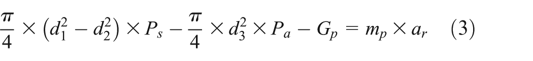
It is assumed that the three stages have the same amount of time, which is 20 ms. Then, with equations (1)–(3), the parameters of the cylinder can be obtained: d1 = 281.1 mm, d2 = 275.4 mm, and d3 = 270.1 mm.
Control valves
According to the above-mentioned analysis, valve V2 has the largest throughflow capability. To obtain a proper set value of valve flow rate, the mean flow rate into or out the cylinder should be calculated. The mean velocity of the piston,

Here, s is the distance completed by the piston during a punching cycle and t is the corresponding time.
Then, the mean flow rate into or out the cylinder can be obtained by equation (5)

Here, A3 is the cross-sectional area of the rod in CV1.
Since the piston should complete 1000 cycles in 1 min and the distance of one cycle is double the press stroke, the mean flow rate into or out the cylinder can be obtained by combining equations (4) and (5), the value of which is about 5968.8 L/min. Therefore, the mean flow rate of valve V2 is about 5968.8 L/min. With respect to the instantaneous flow rate, it is clear that the value is much larger. Therefore, it is assumed that the throughflow capability of the valves V2 has a flow rate of 10,000 L/min under a corresponding pressure drop of 1 bar.
The throughflow capability of valve V3 can be determined by its operation principle. As mentioned above, the fluid volume through valve V3 into CV1 makes the pressure of CV1 raised from Pa to Ps. Then, equation (6) can be obtained

Here, VolCV1 is the volume of CV1 and E is the bulk modulus of hydraulic oil with a value of 1000 MPa.
And


Here, q3 is the mean flow rate of valve V3 and t2 is the operating time of the punching stage.
Equations (6)–(8) can derive that q3 has a value of about 187.5 L/min. Then, it is assumed that the throughflow capability of the valves V3 has a flow rate of 250 L/min under a corresponding pressure drop of 1 bar.
Similarly, the throughflow capability of valve V1 can be determined by the retracting stage. Equation (9) can be derived. Here, q1 is the mean flow rate of valve V1, t3 is the operating time of the retracting stage, and VolCV3 is the volume of CV3
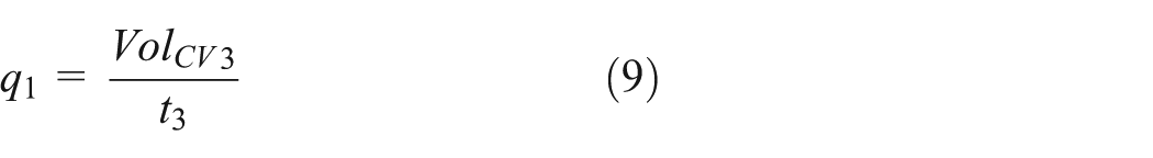
And

Equations (9) and (10) derive that q1 has a value of about 713.9 L/min. Then, it is assumed that the throughflow capability of valve V1 has a flow rate of 1000 L/min under a corresponding pressure drop of 1 bar. With respect to the relief valve, we just assume that it has the same throughflow capability with valve V1, which is 1000 L/min under a corresponding pressure drop of 1 bar.
Operation timing of the control valves
As mentioned above, the three stages have the same working time, which is 20 ms. Then, based on the simulation model in Figure 3, the operation timing of the control valves is illustrated in Figure 4. Here, it is assumed that the control valves could open or close in a very short time.

Operation timing of the control valves.
Accumulator
The accumulator should provide CV1 with enough fluid in the extending stage to avoid the cavitation. Then, the needed fluid volume, Vola, can be calculated by equation (11), which has a result of 2.98 L. Therefore, the accumulator should provide about 3 L fluid for CV1 in the extending stage

Because the volume change of the accumulator is rather quick in the extending stage, it can be assumed as an adiabatic process. Then, equation (12) is obtained

Here, Pg0 is the gas precharge pressure, Pg1 is the operating pressure, Volg0 is the gas volume at Pg0, and Volg1 is the gas volume at Pg1. And

Here, the units of both Volg0 and Volg1 are liter.
To obtain a longer service life, 28 equations (14) and (15) should be satisfied


In order to obtain the above parameters of the accumulator, the value of Volg1 is assumed as 1 L and pg0 is assumed as one-fourth of Pg1. Then, equations (12)–(15) can yield: Pg0 = 1.3 bar, Pg1 = 5.2 bar, and Volg0 = 4 L. Here, the relief pressure of the relief valve is set as 5.2 bar.
Simulation results and analysis
With the obtained basic parameters, the simulation results of the system can be obtained. Here, the load force during the punching stage is modeled by a ramped force, which varies from 0 to 1250 kN at the time interval from 20 to 40 ms and is demonstrated in Figure 5.

Assumed load force during the punching stage.
The piston displacement is demonstrated in Figure 6. The piston could arrive at the maximum displacement with a value of 50 mm at the moment of 17.5 ms. However, the piston cannot overcome the load at the moment of 22 ms, which can be verified in Figure 7. The pressure in CV1 is quite smaller than the preset operating pressure of 210 bar. At the moment of 40 ms, the retracting stage starts, and the piston does not return to the origin at the end of a cycle, which has a distance of about 8 mm. Obviously, with the above parameters, the system for high-speed punching press cannot complete the aimed performance, and the optimization will be carried out in the next section.

Piston displacement in one punching cycle.

CV1 pressure in one punching cycle.
Optimization design
According to Figure 6, the system has an enough fast extending stage but a less powerful punching stage and a slower retracting stage. Many factors could influence the operation performances of the punching press, such as the operating pressure of the accumulator, the rod diameter of the piston, the piston mass. In this section, the optimization of the operation timing of the control valves is mainly discussed.
Operation timing of the control valves
In section “Calculation of basic parameters,” the operation timing of the control valves is set in a rather rough way, which just divides one cycle into three equal parts. According to Figure 6, this timing set is obviously not working for the aimed performance of high-speed punching press. To improve the performance, some points need to be considered in the timing optimization:
It is easy to understand that a short working time of high-pressure fluid is helpful for reducing the system power. Then, the punching time should be as short as possible.
The working time of valve V2 should match the extending velocity of the piston. Otherwise, it may lead to the waste of time. The piston has completed the 50 mm displacement, while valve V2 is still working, which makes a time interval of about 3 ms wasted (see Figure 6).
It should set a longer time for the retracting stage in order to complete the cycle on time.
In summary, it should decrease the extending and punching time and increase the retracting time. Therefore, according to the performance demonstrated in Figure 6, the extending time is set from 0 to 17 ms, the punching time is set from 18 to 32 ms, and the retracting time is set from 33 to 60 ms. The corresponding operation timing of the control valves is shown in Figure 8. And the working time of the load force is the same with the punching time, which will not be described for avoiding repetition in the following sections.
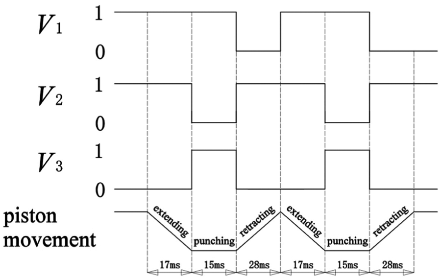
New operation timing of the control valves.
The improved piston displacement is demonstrated in Figure 9. Clearly, the piston could achieve the aimed stroke in the extending stage and return to the origin in the retracting stage. However, it still cannot overcome the load in the punching stage. What is more, the retracting velocity is a little faster, which makes the piston arrive at the origin with about 3 ms earlier.

Improved piston displacement in one punching cycle.
Figure 10 shows the flow rate performance of valve V2. The maximum flow rate of valve V2 occurs at the moment of 14 ms, which has a value of about 14,828 L/min and then the accumulator cannot provide any fluid into valve V2. Then, at the punching stage, a reverse flow rate peak with a value of about 18,590 L/min occurs at the moment of 32.2 ms. The reason for this reverse flow rate peak is that valve V3 has not closed completely, while valve V2 starts to open at this moment. Because the throughflow capability of valve V2 is much larger than that of valve V3, it makes the fluid through valve V3 flow through valve V2 and relief valve into the tank, while not flow into CV1 and work for the punching stage, which makes not only a waste of power but also a reduction in punching capability of the system. Therefore, in the determination of operation timing of the control valves, it should make sure that valve V3 starts connecting to the CV1 after the moment that valve V2 has disconnected from the CV1.

Flow rate of valve V2 in one punching cycle.
Above all, to decrease the extending and punching time and increase the retracting time, it can make the piston return to the origin in time. But the piston still cannot overcome the load in the punching stage. Also, since it needs some time to open or close the valves in practice, the existing operation timing of the control valves does not isolate valve V3 to valve V2 and then leads to a large reverse flow rate through valves V3 to valve V2 into the tank.
Time interval between valves V2 and V3
As mentioned above, a time interval between valves V2 and V3 needs to be set to make sure that these two valves do not work at the same time. The new operation timing of valves V2 and V3 is demonstrated in Figure 11. Valve V2 has closed before the starting of valve V3 with an interval of ΔT, and valve V3 has closed ahead the starting of valve V2 with an interval of ΔT. Here, the value of ΔT is set as 1 ms.
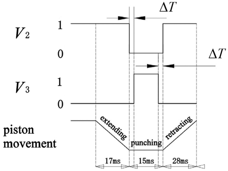
Time interval between valves V2 and V3.
Then, the improved flow rate performance of valve V2 is demonstrated in Figure 12, which has no large reverse flow rate peak in Figure 10. The time interval of 1 ms has made some improvements (see Figure 13). However, the improvement still cannot make the punching stage work well.
Flow rate of valve V2 in one punching cycle with a ΔT of 1 ms.

Difference between the piston displacements in one punching cycle caused by a ΔT of 1 ms.
Other parameters
Clearly, it is hard to achieve the aimed performance of the high-speed punching press without changing other parameters. Through varying those parameters one by one, it can obtain the corresponding results from the simulation models and derive the influence of the parameters on the operation performances of the punching system. Here, since the analysis processes are very similar, they are omitted, and only the results are given as follows:
The accumulator with a large air volume and a small gas precharge pressure is good to increase the extending velocity.
Decreasing d3 could increase the extending velocity and increasing d2 leads to a quicker retracting velocity. A large value of d1 is meaningful not only to increase the extending velocity but also slow down the retracting velocity.
Both a small piston mass and a high operation pressure cause a quick extending velocity.
A large throughflow capability of valve V3 improves the performance of the punching stage.
Final model and analysis
Based on the previous analysis, the final operating principle of the high-speed punching press is demonstrated in Figure 14. 29 Here, a special tank, labeled by upper tank, has taken the place of the accumulator and the relief valve in Figure 1, which is different from other two tanks and placed just on the top of the cylinder in practice. And valve V3 is changed to a three-port valve with three positions. The advantages of these improvements are as follows:
The system is much simple, which leads to a small volume and a lightweight.
The previous accumulator and relief valve are always working at a very high frequency. Compared to the conventional components, it is much difficult to design and manufacture those two components, and the cost is very high. Therefore, removing those two components is good to lower the design difficulty and reduce the cost.
The upper tank can be seen as an accumulator with an infinitely large gas volume and an infinitely low gas precharge pressure, which is helpful to improve the extending and retracting performances.
Just at the start of the retracting stage, valve V3 works at the middle position, which makes CV1 connected to the tank. Then, the CV1 pressure is quickly reduced to a very small value, which makes the retracting velocity much quick.

Final operating principle for the high-speed punching press.
The improved system has four stages: extending stage, punching stage, unloading stage, and retracting stage (see Figure 15). Compared to the previous system, the main difference is the added unloading stage. Thus, only the unloading stage is described in detail. Valve V3 works at the lower position in the unloading stage and then CV1 is connected to the tank, which makes the CV1 pressure rapidly reduced (see Figure 15(c)). Clearly, it decreases the pressure load of the piston and makes a quick movement of the piston in the retracting stage.

Four stages of one punching cycle: (a) extending stage, (b) punching stage, (c) unloading stage, and (d) retracting stage.
With the help of AMESim, the simulation model is shown in Figure 16. Here, valve V2 is a rotational valve, and its flow rate performance can be obtained by a computational fluid dynamics (CFD) simulation method, which is the flow rate value array under the corresponding pressure when the valve opening varies from zero to its full opening. Since the focus of this article is not valve V2, the details of the design and analysis of valve V2 will not be discussed here. And the system parameters are listed in Table 1.
Final simulation model of the high-speed punching press.
System parameters of the high-speed punching press.

rev: revolution.
The operation timing of the control valves is demonstrated in Figure 17. In one cycle, the extending stage works from 0 to 26 ms, the punching stage works from 27 to 32 ms, the unloading stage works for 1 ms, and the extending stage works from 34 to 60 ms. Here, because the unloading stage works for a rather short time, it is seemed as a part of the punching stage and not labeled in Figure 17. Moreover, the time interval between valves V2 and V3 is 1 ms at the start of the punching stage, which is not labeled in Figure 17 either.
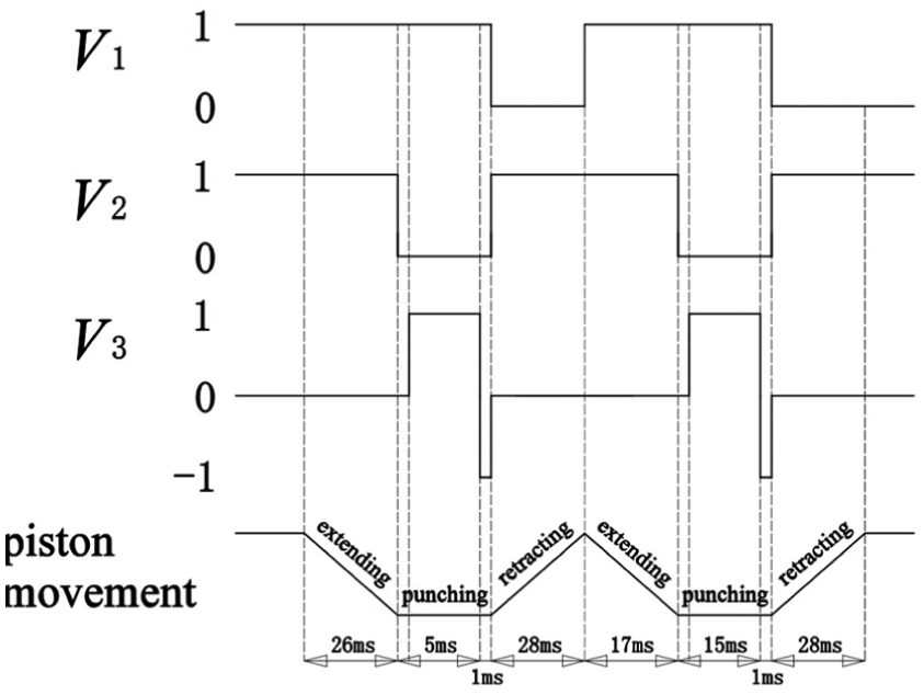
Final operation timing of the control valves.
Then, the displacement performance of the high-speed punching press can be obtained. The piston has completed the aimed stroke, 50 mm, at the moment of 26.2 ms (see Figure 18). Then, the piston could overcome the load force, 1250 kN, to keep at the position of 50 mm for about 5 ms. The CV1 pressure remains at 240 bar in the punching stage, which makes the piston generate a punching force of 1250 kN (see Figure 19). At the moment of 32.4 ms, the piston starts to retract and has returned to the origin at the moment of 59.5 ms. Therefore, the system could complete the aimed performances of the high-speed punching press. Figure 20 shows the piston displacement in three cycles.

Final piston displacement in one punching cycle.
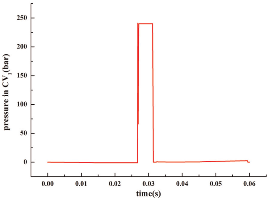
CV1 pressure in one punching cycle.

Piston displacement in three punching cycles.
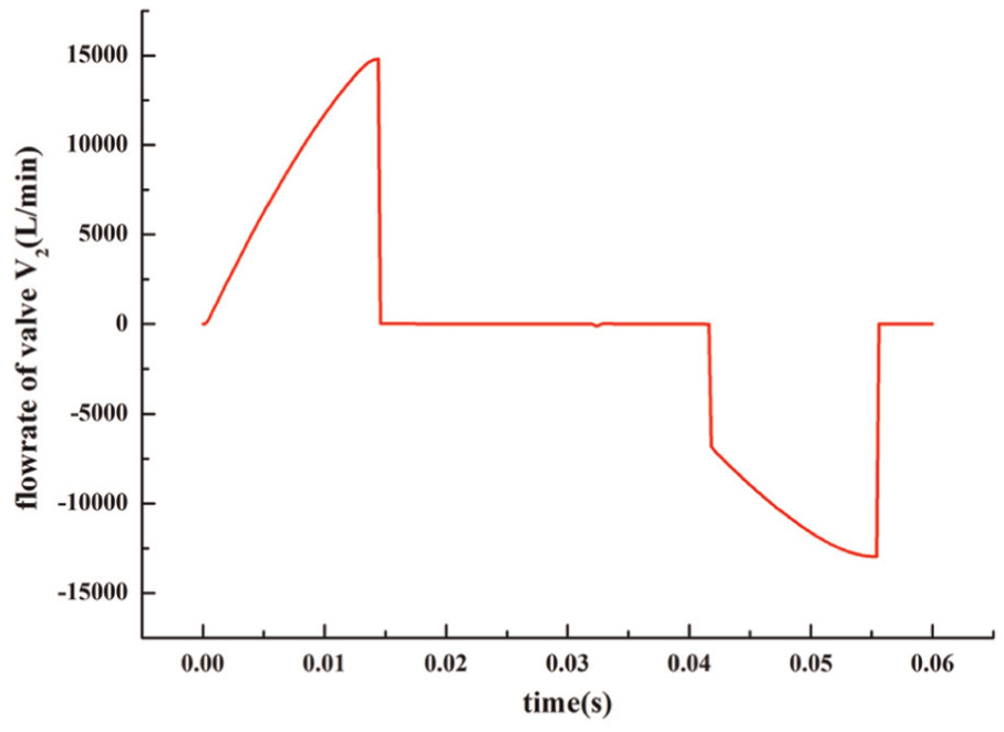
The flow rate performances of the control valves are demonstrated in Figures 21–23. Valve V2 has the maximum flow rate of 11,957 L/min at the retracting stage and a second largest flow rate of 7270.2 L/min at the extending stage (see Figure 21). As demonstrated in Figure 22, valve V3 has a flow rate peak of 1562.2 L/min at the moment of 26.7 ms. At this moment, valve V3 works at the upper position (Figure 15(b)) and a rather large pressure difference between the inlet and outlet of valve V3 leads to this flow rate peak. Another flow rate peak occurs at the moment of 31.3 ms with a value of 300 L/min. At this point, valve V3 works at the lower position (Figure 15(c)), which makes a part of fluid in CV1 flow through valve V3 into the tank. In Figure 23, valve V1 has a maximum flow rate of 599.2 L/min at the extending stage and a maximum flow rate of 524.6 L/min at the retracting stage.

Flow rate of valve V2 in one punching cycle.
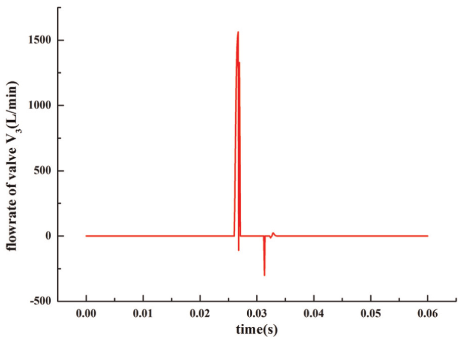
Flow rate of valve V3 in one punching cycle.
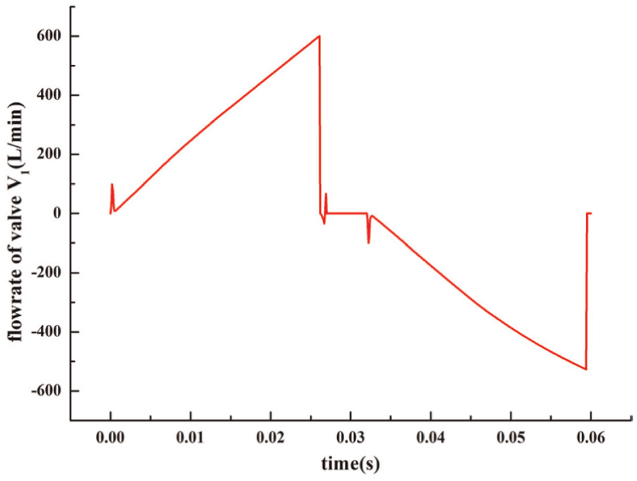
Flow rate of valve V1 in one punching cycle.
Conclusion
In this article, a hydraulic operation principle based on hydraulic vibration technology is proposed for the high-speed punching press with a press force of 1250 kN, a press stroke of 50 mm, and a press velocity of 1000 hpm. By the simulation model built under the AMESim environment, results are obtained and analyzed. Then, optimization design has been carried out, which leads to the final operation principle. The new hydraulic system has a simple structure and a low cost. Moreover, it utilizes a unload stage to raise the retracting velocity. According to the simulation results, the design could achieve the aimed performances of the high-speed punching press. Meantime, the flow rate performances of the control valves are obtained, which is important for the following design and manufacturing of the control valves. Obviously, the control valves are the key part of the design of the high-speed punching press. However, considering the length limitation of this article and the focus of this article, the design of the control valves 30 is not included here and will be described in detail in another article. At the same time, the prototype of the high-speed punching press is in the process of manufacturing, and the experimental research will be carried out in the near future.
Footnotes
Academic Editor: Jun Li
Declaration of conflicting interests
The author(s) declared no potential conflicts of interest with respect to the research, authorship, and/or publication of this article.
Funding
The author(s) disclosed receipt of the following financial support for the research, authorship, and/or publication of this article: This research was supported by the Project of Key Innovation Team of Zhejiang Province (grant no. 2013TD14) and the Project of Major Science and Technology of Zhejiang Province (grant no. 2014C01061).