Annular Poiseuille flows in a transitional regime were investigated by direct numerical simulations with an emphasis on turbulent statistics including the friction factor that are affected by the presence of large-scale transitional structures. Five different radius ratios in the range of 0.1–0.8 and several friction Reynolds numbers in the range of 48–150 were analyzed to consider various flow states accompanied by characteristic transitional structures. Three characteristic structures, namely, turbulent–laminar coexistence referred to as “(straight) puff,”“helical puff,” and “helical turbulence” were observed. The selection of the structures depends on both the radius ratio and the Reynolds number. The findings indicated that despite the transitional state with a turbulent–laminar coexistence, the helical turbulence resulted in a friction factor that was as high as the fully turbulent value. In contrast, with respect to the occurrence of streamwise-finite transitional structures, such as straight/helical puffs, the friction factor decreased in a stepwise manner toward a laminar level. The turbulent statistics revealed asymmetric distributions with respect to the wall-normal direction wherein the profiles and magnitudes were significantly influenced by the occurrence of transitional structures.
Turbulent transition in most wall-bounded shear flows is characterized by subcritical scenarios.1,2 There exists a significant hysteresis between critical Reynolds numbers for global and linear instabilities . For instance, the cylindrical Poiseuille flow (cPf) and plane Couette flow (pCf) are widely known to be linearly stable for any Reynolds number. However, experimental studies demonstrated that both cPf and pCf cannot maintain these laminar states at high Reynolds numbers, no matter how ideal experiment is conducted,3 because unpreventable finite-amplitude disturbance triggers a subcritical bypass transition for . The lower bound of this subcritical transitional regime may be defined as .1 This corresponds to the lowest Reynolds number to sustain turbulence even under a spatiotemporal intermittent state, and this value is important practically and scientifically. In the plane Poiseuille flow (pPf), is known as 5772,4 which is based on the channel half width and the channel centerline velocity of laminar flow, and is lower than in a manner similar to cPf and pCf. The determination of value generally demands massive flow channel (in experiments) or computational resources (in simulations) because of the presence and large-scale patterning of localized turbulence.
The flow transition to turbulence undergoes an intermittent turbulent regime around in the subcritical scenario. As is widely known, a streamwise localized turbulence that is referred to as a puff is typically observed in cPf.5 Recent studies considered the thermodynamic limits of puff decaying and splitting time scales to determine the value of for cPf.6 However, this is not true for both pPf and pCf, as they reveal a more complex transition scenario given the existence of an additional free dimension in the spanwise direction. This contrasts to cPf, which is closed in the azimuthal, or spanwise, direction. The transitional structure observed in pPf and pCf around often forms a two-dimensional (2D) pattern, referred to as “turbulent stripe.”7,8 The turbulent stripe is very large in both the streamwise and the spanwise directions. This stripe pattern is inclined with a certain degree against the streamwise direction. However, the inclination angle of pattern has not been unresolved, because it is influenced by both the computational/experimental horizontal domain sizes and the Reynolds number. In addition, the decaying and splitting processes of turbulent stripe that are very important phenomena for determined as in cPf are still an open issue to date.
This study focuses on the subcritical transition of pressure-driven flows between two concentric cylinders. This is termed as annular Poiseuille flow (aPf). In addition to its merit of a closed system in the spanwise (azimuthal) direction, the aPf may be an ideal flow system to understand canonical wall-bounded shear flows in a comprehensive manner based on the radius ratio, denoted by (where and are the inner and outer radii, respectively). The limiting conditions of represent the flow geometries of a cylinder and a channel between two parallel plates, respectively, despite the existence of a thin inner cylinder for . Actually, a linear stability analysis by Heaton9 demonstrated that aPf should connect two important canonical flows, namely, pPf as and cPf as . Hysteresis is also present between and . In terms of the transitional structure, our previous study10 revealed smooth alternations, with dependence on , of the localized turbulent patterns: helical turbulence, helical puff, and straight puff. Robust helical turbulence corresponding to the turbulent stripe in pPf has been identified for high . With decreasing , the pitch angle of helical turbulence decreases and the flow relaminarizes partly at marginally low Reynolds number for . Finally, a new form of streamwise localized helical turbulence, named helical puff, emerges. For much smaller , the organized structure becomes axisymmetric, and finite-length streamwise localized structures similar to equilibrium puffs in cPf emerges. They reveal that the helical turbulence for high and the straight puff for low are linked by the helical puff for intermediate . Detailed expressions of each structure will be shown later with a discussion of the Reynolds number dependency.
Ishida et al.10 focused only on transitional structures, and statistical properties in aPf were not examined. Hence, this article would describe statistical results including the friction factor. This work uses direct numerical simulation (DNS) of a quenching study from fully developed turbulence to a laminar regime in order to investigate how the transitional structure would affect turbulent statistics. We discuss rather low-dimensional statistical properties in transitional and fully developed turbulent regimes.
Patel and Head11 measured the skin friction to scrutinize the transition regime and how turbulence can be sustained in cPf and pPf, both of which are the limiting cases of aPf. They found that occurred at for cPf and at for pPf (where denotes the bulk mean velocity and D is the pipe diameter). Recently, Samanta et al.12 considered the dependence of the friction factor on initial conditions in cPf focusing on localized structures of puff and spot. Their data provided a well-defined connection between the laminar and turbulent laws and predicted well the upper bound of transitional regime. Since the aPf is widely used in engineering applications, such as heat exchanger, several previous studies examined the friction factor as typified by Rothfus and colleagues.13–15 Those studies suggested the critical Reynolds numbers of the onset and end of the transitional regime,14 which were defined by a slight progressive departure from the theoretical analysis and the empirical equation of cPf (applied for aPf using the hydraulic diameter), respectively. The obtained onset Reynolds numbers of transition for almost agree with those obtained by the recent studies for the global instability of cPf6 and pPf.11 These studies imply that both laminar and turbulent flow patterns exist in the transitional region.
Hanks and Bonner16 employed a theoretical analysis to suggest that the first transition occurs near the inner cylinder and the second transition occurring near the outer cylinder follows the first one. A smaller radius ratio led to larger differences in the value of the critical Reynolds number between the first and second transitions. Moreover, due to the existence of singularity (inner cylinder), the first critical Reynolds number indicated that the flow was always unstable for any Reynolds number as approached zero. In contrast, there was no difference between the first and second critical Reynolds numbers at . Their result also suggested that the dual-flow regime consisting of laminar and turbulent flows near the outer and inner cylinders, respectively, separated at the radial position of maximum velocity, and this typically occurred between the first and the second critical Reynolds numbers. The second critical Reynolds number (on the outer-cylinder side) obtained experimentally14 and theoretically16 was a similar to that for the pPf, although they did not exactly correspond. The second critical Reynolds number for aPf was indicated to connect between cPf and pPf with the variance of . Hanks and Peterson17 also performed an experimental study to verify the theoretical analysis, measured the flow rate by the oscilloscope traces at a low radius ratio , and observed the first and the second transitions. Despite the occurrence of the first transition, no oscillation was observed in the dual-flow regime where oscillations were expected to exist, while disturbed oscillations were detected for the second transition.
Based on these results of existing studies, this study on aPf investigates its subcritical transition scenario from the developed turbulent state to the laminar flow and scrutinizes the presence of the transitional structure in detail to illuminate the manner in which transitional structures affect flow statistics including the friction factor.
Numerical methods
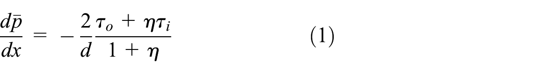
In this study, DNS of pressure-driven flows was performed in two concentric cylinders. A cylindrical coordinate system was adopted as shown in Figure 1. Additionally, we define , which corresponds to the wall-normal distance from the inner wall, and , which corresponds to the azimuthal length. The aPf was driven by a constant uniform pressure gradient (equation 1) in the axial direction x
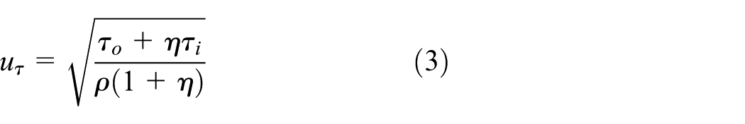
Here, and correspond to the mean wall shear stresses at the outer and inner walls, respectively, and is the gap width between the inner and outer cylinders. A periodic boundary condition was imposed in the x and directions. A non-slip condition was applied on the walls. The fully developed states of flows were considered. The working fluid is an incompressible Newtonian fluid. The friction velocities on the inner and outer cylinder, respectively, are defined as follows
Configuration of the annular Poiseuille flow (aPf).
The averaged friction velocity is defined by the following expression
The fundamental equations for the velocity and the pressure p are given by the equation of continuity (equation (4)) and the Navier–Stokes equation (equation (5))
The superscript + indicates the quantities normalized by the wall unit (i.e. the friction velocity and/or the kinematic viscosity ).
The finite difference method was adopted for the spatial discretization. The fourth-order central scheme was employed in both x and with uniform grids, and the second-order central scheme was in r with non-uniform grids. The non-uniform spacing with fine grids near the walls was given as done by Moin and Kim.18 Further information with respect to the numerical methods we employed can be found in the previous reports.10,19
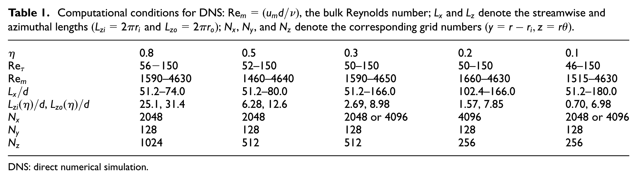
We analyzed several values of and selected five different values of η = 0.1, 0.2, 0.3, 0.5, and 0.8. Table 1 summarizes the simulation parameters. In this study, long streamwise domains of Lx = 51.2d–166.0d were set to capture intermittent structures with long streamwise extents. As the Reynolds number decreased, the computational domain size was elongated in x so that its length would be almost constant in terms of the wall units. As for the azimuthal direction, the present simulation covered the complete domain of . Its normalized azimuthal length should depend on and r.
Computational conditions for DNS: , the bulk Reynolds number; and denote the streamwise and azimuthal lengths ; , , and denote the corresponding grid numbers .
0.8
0.5
0.3
0.2
0.1
56−150
52–150
50–150
50–150
46–150
1590–4630
1460–4640
1590–4650
1660–4630
1515–4630
51.2–74.0
51.2–80.0
51.2–166.0
102.4–166.0
51.2–180.0
,
25.1, 31.4
6.28, 12.6
2.69, 8.98
1.57, 7.85
0.70, 6.98
2048
2048
2048 or 4096
4096
2048 or 4096
128
128
128
128
128
1024
512
512
256
256
DNS: direct numerical simulation.
Results and discussions
Flow regimes and transitional structures
The alternations of dominant transitional structures depending on and are discussed in this subsection. First, we introduce the turbulent fraction to demonstrate the laminar–turbulent coexistence. Then, we would show rather simpler transition processes for high and low , where observed structures are reminiscent of well-known transition scenarios in pPf and cPf. Finally, we describe the transition process for intermediate η = 0.3, which seems to combine the features of transitional structures for lower and higher , as an anomalous case of aPf.
Figure 2 shows turbulent fraction , modified from Ishida et al.,10 that is employed to specify the transition process in aPf. The turbulent fraction illustrates the content rate of turbulence in the flow field. When Ft = 1, the flow regime corresponds to featureless turbulence without any laminar patch. The zero corresponds to a laminar flow. Therefore, intermediate values of indicate the occurrence of turbulent–laminar coexistence. Fully developed or featureless turbulence was observed in the high Reynolds number regime. With decreasing , decreased gradually for all values of . Once the flow undergoes a transitional Reynolds number regime, the laminar region intermittently occurred in the turbulent region, and decreased toward zero.
Turbulent fraction as a function of the bulk Reynolds number. Error bar denotes the magnitude of time variance.
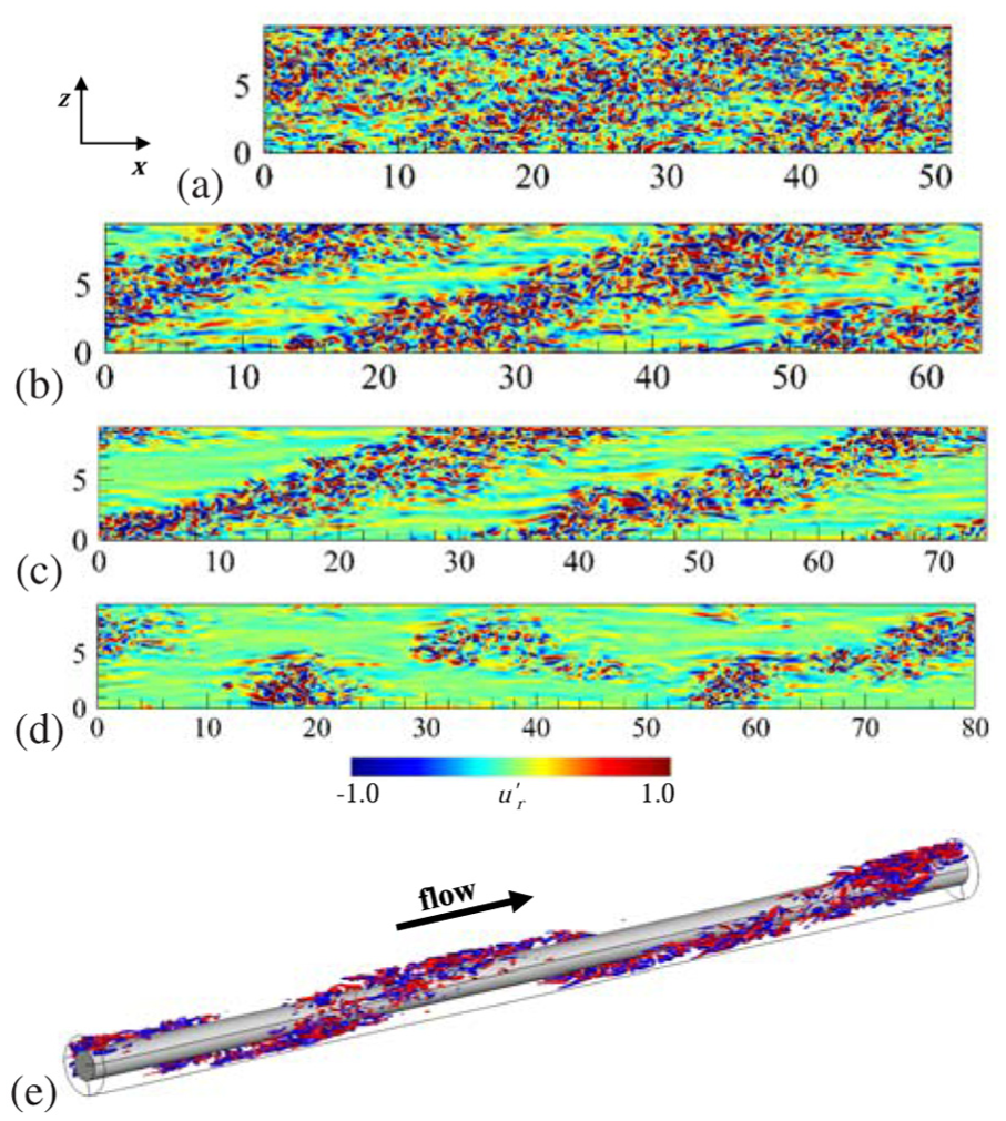
As typical flow regimes describing transitional structures, Figures 3–5 show the 2D contours of wall-normal velocity fluctuations in the plane for different values of . First, let us focus on the case of a rather high of 0.5. As visualized in Figure 3(a), featureless turbulence was observed at despite the occasional appearance of small laminar patches with wispy obliqueness at . Helical turbulence represented by robust oblique laminar–turbulent patterns emerged at . This helical turbulence corresponded to a stripe pattern observed in the plane channel flows (pCf and pPf). The laminar region expanded with a decrease in , and the helical turbulence was marginally modulated and collapsed at , as shown in Figure 3(d). Therefore, several helical puffs (with finite streamwise lengths) and turbulent spots were observed for a very low and narrow Reynolds number range near . Whereas the previous study10 suggested that the helical puff occurred only for η = 0.3, we newly observed the helical puff even for high . Xiong et al.20 also reported similar observations in the pPf at very low Reynolds numbers, demonstrating the occurrence of a localized oblique pattern around even for pPf . In Figure 3(e), a three-dimensional (3D) visualization of the helical turbulence in aPf was presented to aid in easy understanding. In contrast to the stripe pattern observed in pPf, the helical turbulence coils around the inner cylinder because the flow system of aPf is closed in the azimuthal direction. The transition process for η = 0.8 was similar to that for . Therefore, clear helical turbulence can be observed for .
Two-dimensional xz-plane contours of wall-normal velocity fluctuations at Reτ = (a) 80, (b) 64, (c) 56, and (d) 52 for . The mean flow direction is from left to right and (e) three-dimensional visualization of wall-normal velocity fluctuations at (, red; , blue).
Two-dimensional xz-plane contours of wall-normal velocity fluctuations at Reτ = (a) 80, (b) 64, (c) 60 (d) 56, (e) 54, (f) 52, (g) 50, and (h) 48 for . The color range is the same as that in Figure 3.
Two-dimensional xz-plane contours of wall-normal velocity fluctuations at Reτ = (a) 80, (b) 64, (c) 56, (d) 54, and (e) 52 for . The color range is the same as that in Figure 3.
A small radius ratio must be expected to reveal transitional states similar to those in cPf. Figure 4 shows the flow fields at . The featureless turbulence without any laminar patch was confirmed at . Even at , almost the whole field is dominated by the turbulent region and sometimes small laminar patches occur, as given in Figure 4(b), although helical turbulence emerges for high . A streamwise localized laminar–turbulent pattern corresponding to the puff in cPf was found below . Even for small of 0.1, oblique interfaces between turbulent and laminar region were rarely observed at slightly high values of . As decreased from 60 to 48, the number of puffs or streamwise length of the puff was decreased. The puff in aPf exhibited splitting, decaying, and combining processes, which were similar to those of the puff in cPf.21,22 At low , the combining process could not be detected and the probability of splitting decayed analogous to the previous study.22 Although the puffs split, one of the separated puffs immediately decayed in aPf at . At , any puff splitting was not observed, the streamwise size of the puff changed slightly and increased/decreased with time. The flow relaminarized at , and Figure 4(h) shows an instant field before the relaminarization completed.
As well as the other cases shown above, the intermediate of 0.3 resulted in the flow state of featureless turbulence at (see Figure 5(a)). At , the helical turbulence similar to that observed for occurred, as shown in Figure 5(b). There was a breaking-off point of helical turbulence, and streamwise localized helical turbulence (called helical puff) was observed at . Figure 5(c) shows the flow field at , where mixed helical and straight puffs can be observed. The obliqueness of the helical puff decayed, the straight puff infrequently occurred at lower , and the probability of occurrence of a straight puff was increased compared to that of the helical puff, with decreasing . At , the transitional structure immediately decays and the flow becomes laminar. This complex transition process was also found for . The occurrence ratio of straight puff increases more compared to . Additionally, helical turbulence could not be recognized for even at high values of . A future study will discuss the separation of these complex transition processes based on both and .
Friction factor
The friction factor, denoted by , is defined by following equation as shown in Figure 6
(a) Friction factor , (b) product of , and (c) extended figure of around the transitional regime.
The Blasius empirical friction law in the turbulent regime is also shown for a comparison. The laminar solution depends on . In the laminar solution of , the definition of is as follows
With respect to cPf and pPf as the limiting cases of aPf, values are 1.0 and 1.5, respectively. In order to facilitate an easy understanding of the transition process, the product as a function of is also plotted in Figure 6(b) and (c). The friction factor at high Reynolds numbers are in agreement with the empirical function. Furthermore, maintained high value even at lower Reynolds numbers in the transitional regime, when the flow is accompanied by the helical turbulence (for ). However, given the localization of helical turbulence in the x direction and the emergence of a helical puff, deviated from the empirical function toward a laminar solution, as seen at for η = 0.5. With respect to intermediate of 0.2–0.3, maintained a high value similar to that for high . This must be also because of the presence of helical turbulence or helical puff. A further decrease in induces a sudden drop of , retaining the same values of and gradually approaches a laminar solution. It should be noted again that the present flow system is driven by a fixed-mean pressure gradient and depends on the flow state. Under such a condition, once a relaminarization occurs, the bulk Reynolds number should increase significantly with a fixed and lowered . In this sense, there exists an overlapping region around for . This must be caused by the alternations of transitional structures from helical turbulence to puffs through helical puff, due to decrease in for moderate . With respect to , gradually decreased with the Reynolds number after the occurrence of the straight puff. There is no overlapping region, unlike that observed for intermediate because the transitional structure does not change from straight puff at any Reynolds number for η = 0.1.
As described above, in the transitional regime considerably depends on the form of transitional structure. Similar aspects can be confirmed from the turbulent fraction that is given in Figure 2. Both and would maintain magnitudes as high as those of featureless turbulence, if the transitional structures forms helical pattern. Such an enhancement of turbulence contributions is weakened in the following order: helical turbulence → helical puff → straight puff.
Figure 7 shows the local friction velocities at the inner and outer cylinders (denoted by and , respectively) and the ratio of the friction Reynolds number on the inner and outer cylinders (denoted by and , respectively). The difference between and increases at low and small when compared to the difference at high and large . Specifically, the difference enlarges noticeably when , which corresponds to a shift of the regime from the featureless turbulence to a transitional state of helical/straight puff. On the outer-cylinder side, does not depend much on both and , and it is approximate to the global friction velocity defined by equation (3). In contrast, is significantly different from and depends on and . The distribution of the ratios of the friction Reynolds number for all values of was almost a linear distribution, as shown in Figure 7(b). This implies a less dependency of the ratio on the global Reynolds number .
(a) Friction velocity on the inner and outer cylinders as a function of . (b) Comparison of the friction Reynolds number based on the inner friction velocity versus the friction Reynolds number based on the outer friction velocity. If , it should be .
Here, let us briefly describe a background mechanism of the high friction velocity, that is, the large velocity gradient, on the inner-cylinder wall, which can be seen in Figures 7(a) and 8. In aPf, the inner cylinder should be associated with a large number of intensive sweep and ejection events that can be attributed to the transverse curvature effect.23 In addition, elongated streaky structures near the inner wall are more active than those along the outer wall. The turbulent motions on the outer wall are similar to those near the flat wall of cPf and pPf. These phenomena have also been studied by Satake and Kawamura.24 They discovered that a high-speed fluid impinging against and across the inner rod would form a wake-like region behind the rod and a large-scale wall-normal motion in the large low-pressure region. This distinctive turbulent event increases the friction Reynolds number on the inner cylinder, and this phenomenon leads an asymmetric profile especially for low . The asymmetric properties are discussed also in the following sections.
Mean streamwise velocity profiles. The line types indicate different values of , and the colors correspond to different values of . The inner-cylinder wall corresponds to , while the outer one is at .
Mean flow statistics
The mean velocity profiles are presented in Figure 8. In the figure, the profiles of are slightly tilted toward the inner cylinder (y/d = 0) showing asymmetric distributions with respect to the gap center. For large values of , the distributions are rather symmetric at any and similar to the mean velocity profile in pPf. The peak position shifts to the inner-cylinder side, in particular, for low . As for the Reynolds number effect, the peak of does not move so much when decreases from 56 to 52, but both the peak value and the bulk velocity (normalized by ) increase noticeably. This is because those flows are already in the intermittent state and a decrease in the Reynolds number would expand laminar regions. In terms of transitional structures among the helical turbulence and the helical/straight puffs, any significant difference cannot be observed in the profiles. However, with respect to the decreasing from 80 to 56, the peak position of moved toward the gap center (y/d = 0.5) and the asymmetric property is suppressed particularly for low . This implies that the asymmetric property of the core region would be moderated in the transitional regime accompanied by large-scale intermittent structures, while featureless turbulence at a high Reynolds number reveals an asymmetric profile due to the aPf geometry. Because of this, the profile in the transitional aPf even for is more dissimilar to cPf, in which has a peak at and decreases monotonically with . However, both flows exhibit straight puffs, as shown in Figure 4(f)–(h). It is interesting to note that the flow statistics including the mean velocity profile in the subcritical regime were dissimilar to cPf, although the flow structure is analogous in both flows.
For reference, Table 2 assembles the types of dominant transitional structures that are found in each case we focus in this section. As seen in the table, gives rise to the featureless turbulence at any . Below this Reynolds number, the transitional structure is formed and depends on . At , only the straight puff can be formed, as discussed with Figure 4. However, we have observed the helical shape of structures at in Figure 3. For , the helical puff seems unstable and might cycle through breakup and reshaping.
Transitional structure observed in the selected cases. The value sets of the parameters are corresponding to those shown in Figures 8–11.
Featureless Turbulence
Featureless Turbulence
Featureless Turbulence
Helical Turbulence
(Helical) Puff
Straight Puff
Helical Puff
Straight Puff
Straight Puff
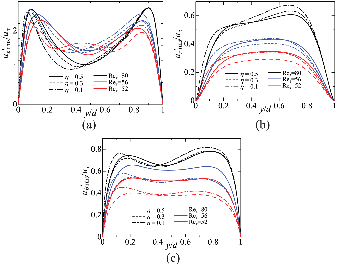
Figure 9 shows the root mean square value of each fluctuating velocity component. In Figure 9(a), the streamwise turbulent intensity shows asymmetric distributions with two clear peaks near the inner and outer cylinders. The difference between the two peaks increases with smaller values of , and the peak near the inner cylinder is larger than that near the outer cylinder. It should be noted that, if scaled with each friction velocity (either or ), the inner peak of is much lower than the outer one of (figure not shown here). In a manner dissimilar to the , the asymmetricity in a profile is increased at low values of as well as . The two near-wall peaks for the high of 80 exhibit the almost same magnitude. At this Reynolds number, the fully turbulent state might reduce the intensity gap between both sides and, as a result, three curves with different are roughly matched. This aspect can be similarly seen in the other components. An interesting distribution of is observed at for η = 0.1 and 0.3, and a third peak is observed around the gap center. This centerline peak must be attributed to localized (straight) puffs with very large laminar regions, as shown in Figures 4(f) and 5(e).
In Figure 9(b) and (c), and indicate skewed profiles with higher peaks near the outer cylinder at a high value of . Given decrease in , the difference between the peaks near the inner and outer cylinder of decreases and an almost plateau region is observed around the gap center. With respect to this plateau region, we found that the cases in the presence of helical turbulence always provide large and compared to the cases of puff. For instance, for is 10%–20% larger than that for , as given in Figure 9(c). These results suggesting an enhanced turbulent intensity in the helical turbulence are in consistency with the above-mentioned high in the transitional regime. A high-value distribution of near the inner cylinder is the same trend with that of for low .
Figure 10 shows the Reynolds shear stress . The radial position of the zero Reynolds shear stress moves slightly toward the inner cylinder for low values of , while the zero value for pPf should be located at the center of the gap. The zero position shifted to the channel center with a decrease in the value of from 80 to 56, as does the peak position of (Figure 8). The zero position approaches the center of the gap even for low values of with decrease in . With respect to the magnitude of Reynolds shear stress, we may detect tendencies similar to those in the turbulent intensity: the larger peak near the inner cylinder for low , the weakening due to decay from featureless turbulence, and the enhancement by the presence of helical turbulence.
Reynolds shear stress.
Figure 11 shows the turbulent energy, denoted by . As widely known, turbulent motion is vigorous near the wall. With respect to the aPf, the turbulence is more activated near the inner cylinder than near the outer cylinder. In contrast, the peak of k near the outer cylinder is slightly higher only at the high value of . Therefore, this enhanced turbulent fluctuation near the inner cylinder was prominent when the transitional structure occurred. Note again that in terms of normalization by each wall units, the magnitude of k becomes lower on the inner-cylinder side than on the outer side. It may imply that the near-wall coherent structure common to plane-wall turbulence may tend to be absent near the inner cylinder, in particular, under the transitional state. Hanks and Bonner16 proposed a picture of the dual flow, that is, the first transition from the inner-cylinder side, in aPf. In contrast, our DNSs have demonstrated no dual flow and shown a less active turbulence near the outer-cylinder wall. For , the streamwise localized puff with a large laminar regime led to high fluctuations around the gap center, as discussed in the distribution of .
Turbulent energy.
Conclusion
This study on aPfs has investigated the Reynolds number and radius ratio dependencies of the subcritical transition process, friction factor, and turbulent statistics, by means of DNSs.
The results indicated that the transition process of aPf depended on both and . Clear helical turbulence was observed for high . Even for such a high , helical puffs emerged in a very narrow range of Reynolds number around . In contrast, with respect to low , straight puffs similar to those in cPf occurred in low ranges. With respect to intermediate values of η (η = 0.2 and 0.3), given decrease in , the transitional structure varied and included helical turbulence, helical puff, and straight puff.
The occurrence of the transition structures considerably influenced the friction factor and turbulent fraction . When the flow regime corresponding to helical turbulence, the friction factor and turbulent fraction maintained a high value that was similar to that for fully turbulent regime. However, the friction factor immediately decreased, once the transitional structure was localized in the streamwise direction and formed the helical/straight puff. For low , only the straight puff was organized independently of , and decreased toward laminar solution monotonically. In contrast of this monotonic trend, an overlapping region existed around for intermediate . This non-monotonic trends of and must be caused by the alternations of transitional structures. As mentioned above, the shape of transitional structure depended not only on but also on . For η = 0.3, helical turbulence was sustained only in a small range of high , where the intermittent regime occurred. With decrease in , the helical turbulence changed into the straight puff through the helical puff. Attributed to these alternations of transitional structures for a fixed intermediate , both and followed two different paths of the helical turbulence and the straight puff.
The turbulent statistics in aPf corresponded to an asymmetric distributions with respect to the gap center. With respect to the streamwise mean velocity profile, the asymmetricity was strong when was high and was small. Even for low values of , the distributions became symmetric once the transition from featureless to intermittent turbulence occurred. The transitional structure for low was a puff (similar to that in the cPf but different from the oblique pattern in pPf). Hence, in the subcritical regime, it was interesting to note that exhibited dissimilarity with the cPf, although the flow structure was analogous for both flows.
In contrast, the distributions and magnitude of turbulent intensities exhibited complex behaviors. The turbulent intensities displayed strong peaks near the inner cylinder with decrease in , whereas the peak near the outer cylinder was higher at high . This is due to the difference in the local friction velocity between the outer and inner cylinder, which becomes large significantly after a shift from featureless turbulence to the transitional regime. With respect to the transitional regime, the turbulent intensities were enhanced, in particular, when the helical turbulence occurred. The third peak appeared around the gap center, when there existed the straight puffs among which large laminar regions emerged.
Footnotes
Acknowledgements
The present simulations were performed on NEC-SX supercomputers at the Cyberscience Centre of Tohoku University and at the Cybermedia Centre of Osaka University.
Academic Editor: Bo Yu
Declaration of conflicting interests
The author(s) declared no potential conflicts of interest with respect to the research, authorship, and/or publication of this article.
Funding
The author(s) disclosed receipt of the following financial support for the research, authorship, and/or publication of this article: T.I. was supported by a Grant-in-Aid from Japan Society for the Promotion of Science (JSPS) Fellowship #26-7477. This work was partially supported by Grant-in-Aid for Young Scientists (A) #16H06066 from JSPS.
References
1.
MannevilleP.On the transition to turbulence of wall-bounded flows in general, and plane Couette flow in particular. Eur J Mech B2015; 49: 345–362.
2.
MannevilleP.Transition to turbulence in wall-bounded flows: where do we stand?Mech Eng Rev2016; 3: 15–00684.
3.
PfennigerW. Transition in the inlet length of tubes at high Reynolds numbers. In: LachmanGV (ed.) Boundary layer and flow control. Oxford: Pergamon Press, 1961, pp.970–980.
4.
OrszagSA.Accurate solution of the Orr-Sommerfeld stability equation. J Fluid Mech1971; 50: 689–703.
5.
WygnanskiIJ. On transition in a pipe. Part 1. The origin of puffs and slugs and the flow in a turbulent slug. J Fluid Mech1973; 59: 281–335.
6.
AvilaKMoxeyDLozarAD. The onset of turbulence in pipe flow. Science2011; 333: 192–196.
7.
TsukaharaTSekiYKawamuraH. DNS of turbulent channel flow at very low Reynolds numbers. In: Proceedings of the fourth international symposium on turbulence and shear flow phenomena, Williamsburg, VA, 27–29 June 2005, pp.935–940. Danbury, CT: TSFP Digital Library Online, Begell House Inc.
AbeHKawamuraHMatsuoY.Direct numerical simulation of a fully developed turbulent channel flow with respect to the Reynolds number dependence. J Fluid Eng2001; 2: 382–393.
20.
XiongXTaoJChenS. Turbulent bands in plane-Poiseuille flow at moderate Reynolds numbers. Phys Fluids2015; 27: 041702 (7 pp.).
21.
MoxeyDBarkleyD.Distinct large-scale turbulent-laminar states in transitional pipe flow. PNAS2010; 107: 8091–8096.
22.
ShimizuMMannevillePDuguetY. Splitting of a turbulent puff in pipe flow. Fluid Dyn Res2014; 46: 061403 (13 pp.).
23.
LiuNSLuXY.Large eddy simulation of turbulent concentric annular channel flows. Int J Numer Meth Fl2004; 45: 1317–1338.
24.
SatakeSKawamuraH. Large eddy simulation of turbulent flow in concentric annuli with a thin inner rod. In: DurstFKasagiNLaunderBE. (eds) Turbulent shear flows 9. Berlin, Heidelberg: Springer, 1995, pp.259–281.