
Abstract
The diffuser inlet width is a key geometric parameter that affects submersible pump performance. On the basis of diffuser characteristic curve analyses, diffusers with different inlet widths and the same impeller were equipped to construct a submersible pump model through the use of AutoCAD software. The performance curves of the submersible pump, with six diffuser inlet widths, were obtained using computational fluid dynamics method. Simultaneously, the simulation results were tested with the experimental method presented in this article. The results show that the optimum value of the inlet width (b3 = 50 mm) is larger than the experience-based one. With an increase in the inlet width, the optimum operating point of a submersible pump offsets to a larger flow rate. When the guide blade inlet width is approximately 40–55 mm, the submersible pump efficiency is relatively high, approximately 75.9%–83.7% capacity, and the flow rate is approximately 105–135 m3/h. The numerical results of submersible pump performance are higher than those of the test results; however, their change trends have an acceptable agreement with each other. The practical significance is supplied by changing the inlet width of the diffuser to expand the scope of use.
Introduction
Submersible pumps, a main apparatus of general machinery, have been widely used in field irrigation, sewage disposal, and urban drainage. However, the submersible pumps on market do not have high performances. 1 From an energy-saving viewpoint, 2 further exploration of design and production to improve the performance of submersible pumps has important theoretical significance and application value.
The main flow components of submersible pumps are the impeller and diffuser, both of which jointly affect performance. The diffuser provides important energy conversion in the submersible pump and, to some extent, determines its structure and performance. 3 Data show that the hydraulic loss from the diffuser accounts for 40%–50% of the total hydraulic loss by the pump. 4 If the diffuser and the impeller are not matched, not only the efficiency of the pump is reduced, but also, to a certain extent, the stability of the pump performance is affected, as well.
Most scholars focus on the calculation and internal flow field analyses of the impeller and the volute,5–9 with less emphasis on submersible pumps with space diffusers. Any research on the characteristics of diffusers and their effect on submersible pump performance is also limited to qualitative research,10–12 in particular, research13–15 on diffusers and impellers is less frequent.
With the development of computer technology, the numerical simulation method has been used widely in fluid machinery by computational fluid dynamics (CFD) techniques, which can predict pump performance and optimize the design a level equivalent to practical engineering. 16 However, studies on calculations involving the diffusers of submersible pumps are rare.17–19 This work focuses on submersible pump performance with different diffuser inlet widths. With the exception of inlet width, all the diffusers had the same geometry and fitting with the same impeller separately. The characteristic curve variations of the diffuser inlet widths were analyzed in terms of working principles and structural designs. Numerical calculations were conducted in FLUENT to analyze pump performance. In the case of an unchanged impeller, a high-efficiency zone was obtained by changing the inlet width of the diffuser, which could potentially increase and expand the scope and use of submersible pumps.
Diffuser structure and characteristic curve analysis
The diffuser can successfully transport liquid to the next-stage impeller or export. The diffuser structure of submersible pump is shown in Figure 1, and its main parameter type includes inlet parameters, outlet parameters, axial length, blade numbers, and blade thickness. The visible parameters in the diagram are as follows: maximum diameter of inner flow line and outflow line in entrances D3 and D4, diffuser inlet width b3, maximum diameter of inner flow line and outflow line at exits D5 and D6, and axial length of blade Ld. Among them, the diffuser inlet parameters connect closely with the impeller outflow liquid. The diffuser inlet width b3 is an important structural parameter, which directly affects the submersible pump operating point position. Therefore, under the conditions of same impeller, by changing the inlet width of the diffuser to change the position of the optimum operating point of the submersible pump, submersible pumps that perform differently can be obtained.

Sketch map of the diffuser geometry: (a) blade axial projection and (b) cross section.
Determining the optimum operating point
The optimum operating point usually refers to the flow and head at maximum working efficiency. The optimum operating point of the submersible pump is the best operating point under the combined impeller and the diffuser. When the impeller inlet is without pre-swirl, the characteristic equation of the diffuser can be derived from centrifugal pump basic equations and the diffuser inlet velocity triangle. 20 The equation is as follows

where Q is the pump flow, n is the pump speed, ηh is the hydraulic efficiency, b3 is the diffuser inlet width, ψ3 is the diffuser inlet exclusion coefficient, and α3n is the diffuser inlet angle.
The characteristic equation of the impeller can be derived from centrifugal pump basic equations and the impeller outlet velocity triangle. 20 The equation is as follows

where D2 is the impeller outlet diameter, p is the theoretical head correction factor, β2n is the impeller blade outlet angle, ηV is the volumetric efficiency, b2 is the impeller outlet width, ψ2 is the impeller outlet exclusion coefficient, and the remaining symbol is as given previously.
When the impeller inlet is without pre-swirl, the optimum operating point of the submersible pump can be obtained by solving equations (1) and (2).
Influence on diffuser characteristic curves
The diffuser is an important flow component in the submersible pump. Changing the flow channel geometry parameters affects the performance characteristic curve of the submersible pumps. Position changes of the optimum operating point of a submersible pump can be reflected through changes in the diffuser characteristic curve.
From equation (1), it can be seen that the diffuser characteristic curve is a half-line passing through the origin of the coordinates. Its physical meaning is defined as follows: when the impeller inlet is without pre-swirl and when the conditions of n, α3n, ψ3, and b3 are certain, if the diffuser inlet width b3 corresponds to the optimum value and the impeller flow stream angle α3 is equal to the diffuser inlet angle α3n, then liquid collision flow into diffuser will not occur. At this time, the diffuser hydraulic efficiency, ηh, is at its highest and the characteristic curve is at its best (Figure 2). When the diffuser is operating at a nonoptimal point, the hydraulic efficiency, ηh, will drop, and the pump must inevitably deviate from its maximum efficiency point for design performance. Amidst the many nonoptimal characteristic curves, only one is the best.

Diffuser characteristic curve with a different inlet width.
The impeller characteristic equation (2) is a decline convex curve with flow increases.
According to equation (1), the slope of the diffuser characteristic curve is as follows

In this formula, K is the slope of the diffuser characteristic curve. Its value is related to flow channel geometric parameters, including b3, ψ3 (not be considered because its change scope is limited), α3n, n, and ηh, where diffuser inlet width has a significant impact on submersible pump performance.
Under the conditions of constants α3n, n, and ηh, b3large → Ksmall → tanφsmall → φsmall, on the contrary, b3small → Klarge → tanφlarge → φlarge. That is to say, with the increase in inlet width, the angle, φ, of the diffuser characteristic curve and the horizontal axis (flow) is reduced, and the optimum operating point of the submersible pump offsets to the larger flow rate. Otherwise, the optimum operating point of the submersible pump offsets to the small flow rate when the diffuser inlet width is reduced. Its characteristic curves are shown in Figure 2.
Numerical calculations and results’ analyses
Mathematical model
Geometric model
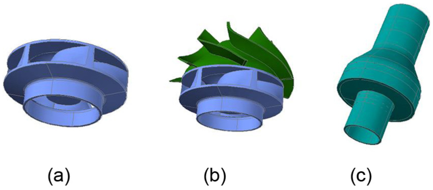
Submersible pumps of different properties can be obtained through different inlet width diffusers and the same impeller combinations. The commonly used submersible pump (250QJ125; Zhejiang Kaicheng Pump Valve Co.) was selected as the research object. Its main parameter design conditions are as follows: rated flow: Q = 125 m3/h, single-stage head: H = 16 m, speed n = 2875 r/min, and specific speed: ns = 244. Table 1 gives the main geometric parameters of the impeller. AutoCAD three-dimensional modeling is shown in Figure 3(a).
Main characteristics of impellers.

Calculation model.
On the basis of the principle of diffusers matching the impeller, the preliminary prepared diffuser geometric parameters are presented in Table 2.
Main characteristics of diffusers

The diffuser inlet width is usually determined by the impeller outlet width plus the front and back blind flange thicknesses, according to the structure and to add the necessary clearance. The changing values of the diffuser inlet width (b3) are 35, 40, 45, 50, 55, and 60 mm.
The geometric models of the submersible pumps were established by using AutoCAD. To make the impeller liquid flow smoothly into the diffuser and to enhance pump efficiency, as well as to obtain more accurate descriptions of the submersible pump speed, the pressure, and other parameters, the concentric cylinder height of 160 mm was fixed on impeller inlet section. At the same time, the outlet side of the diffuser also added a of 160-mm-high concentric cylinder, such that the liquid could be fully developed. Figure 3(b) and (c) gives the impeller and the diffuser combined calculation model.
Model for fluid flow
The submersible pump working medium is water; therefore, the flow can be regarded as incompressible steady flow. Fluid motion equations are the Reynolds-averaged Navier–Stokes equations. Renormalization-group (RNG) turbulence model can better deal with the flow which has higher strain rate and larger bending streamline. Based on the submersible pump diffuser blade, bending degree is relatively larger, RNG k–ε model was chosen to do simulation, which can more accurately reflect the fluid flow condition. Standard wall functions were used in near-solid wall area, and the coefficients are as follows: k = 0.04, ε = 0.2, Cµ = 0.09, C1 = 1.43, and C2 = 1.67. The value of y+ is 60.
Changes in the geometric size of the pump will cause changes in the Reynolds number and then cause changes in the hydraulic loss, that is, changes in efficiency. The Reynolds number can be calculated using equation (4)

where ρ is the liquid density, v is the average flow rate of the liquid through the impeller (take the relative speed of the blade inlet and outlet sides), d is the hydraulic diameter, and µ is the coefficient of viscosity.
Based on the study of the pump using rated flow (Q = 125 m3/h) and fixed speed (n = 2875 r/min), the Reynolds number is a relatively fixed value. By calculation, the approximate value of Reynolds number for the CFD simulation is 7.5 × 10⁶.
A uniform axial velocity based on the mass-flow rate is specified at the inlet, which is perpendicular to the impeller inlet cross section, and the tangential velocity and radial velocity were zero. The outlet boundary was assumed to be outflow. Surfaces such as the impeller and the diffuser were no-slip, and the standard wall function was approached to the turbulent flow of the near-wall.
Mesh generation and algorithm
The whole hydraulic passage of the submersible pump was taken as the computational flow domain. The flow domain consisted of four parts: (1) import extension, (2) impeller region, (3) diffuser region, and (4) outlet extension. The plane between the two adjacent subregions was taken as the interface. The whole mesh generation process was performed using Gambit software, the inlet and outlet sections were meshed structured grids, and the zones of diffuser and impeller were meshed hybrid grids. Meanwhile, the vane surface grid was refined. In theory, the calculation accuracy will be improved with the increase in the grid number. However, considering the configuration of the computer and computational efficiency, the number of grid cannot be too large. In this article, five different grid numbers were selected for the numerical simulation, and the results were indicated in Table 3.
Grid number analysis.
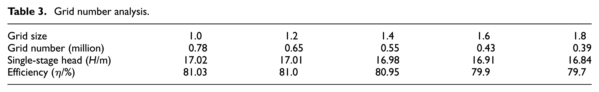
Table 3 shows the results of grid number analysis. When the grid number is larger than 0.65 million, the single-stage head and the efficiency change slightly, indicating that the numerical simulation results are tending stable. Considering the computer’s calculation capability, the grid size of 1.2 is selected to carry out the study. The grid number was 0.65 million, and all the mesh skew was <0.91.
The internal flow field simulation chooses a separation implicit solver, and second-order upwind discretizations were used for the convective and the diffusive. The pressure–velocity coupling was calculated by means of the SIMPLEC algorithm. 21 Each relaxation factor was as follows: pressure options: 0.3, velocity options: 0.7, turbulent kinetic energy options: 0.5, and turbulent dissipation options: 0.3. The submersible pump model includes the rotating region (the impeller fluid) and the stationary region, and the coupling between them is solved via the multiple reference frame (MRF).
Numerical results and discussions
Pump performance prediction
By citation of the submersible pump performance prediction theory, 22 the Q–H and Q–η curves were obtained by FLUENT simulation under multiconditions. Those performance curves with different diffuser inlet widths are shown in Figure 4. The submersible pump performances were analyzed by those curves.

Pump performance predictions: (a) b3 = 35 mm, (b) b3 = 40 mm, (c) b3 = 45 mm, (d) b3 = 50 mm, (e) b3 = 55 mm, and (f) b3 = 60 mm.
Figure 4 indicates that the diffuser characteristic curve is a half-line passing through the origin of coordinates and the maximum efficiency operating point. When the diffuser inlet width is small, the angle between the half-line and the horizontal axis is large; otherwise, the angle is small. Along with the increase in diffuser inlet width, the angle between diffuser characteristic curve and the horizontal axis had a decreasing trend. This conclusion is consistent with the theoretical analysis.
The original submersible pump (b3 = 45 mm) efficiency η of the 250QJ125 pump was 81%, and the other submersible pump efficiencies under different inlet widths were, respectively, 66.2%, 75.1%, 83.2%, 74.4%, and 65.3%. In addition to the submersible pump efficiency of 50-mm diffuser, inlet width improved by 2.2%, whereas the rest had varying degrees of decline, that is, 14.8%, 5.9%, 6.6%, and 15.7%.
With an increase in inlet width, the diffusion segment structure of the diffuser changed from long and narrow to wide and short. When the value of the inlet width is small (b3 = 35 mm), and because inlet throat area is also small, flow velocity is large, flow pattern is poor, energy loss is large, and pump head is 15.8 m. Also compared with the original, the diffuser is reduced to 1.21 m, and pump efficiency is lower. When the value of the inlet width is large (b3 = 60 mm), the pump head is 11.88 m, and the conversion of speed energy to pressure energy effect is poor, primarily because the inlet throat area is too large and the flow path length is too short; hence, the flow that cannot diffuse sufficiently diffused into the diffuser and the outflow liquid has a big tangential velocity component. When the inlet width is 40–55 mm, the flow in the diffuser can be spread evenly, the flow state is relatively good, the tangential velocity component of the outflow liquid is small, and the pump efficiency is relatively high. The optimum value of the diffuser inlet width exists, that is, b3 = 50 mm; however, it is larger than the experience-based one. Therefore, to avoid flow losses, that is, if the diffuser inlet width value is too small or too large, the value of the inlet width can be slightly larger than the experience-based one.
Outflow liquid from the impeller will generate an impact loss at the entrance of the diffuser. In this case, the hydraulic loss conditions differ in regard to diffuser inlet width change, and it is possible to establish an additional best efficiency point. Whereas, the operating condition corresponding to the best efficiency point is bound to change. As shown in Figure 4, along with an increase in the diffuser inlet width, the optimum operating point of the submersible pump offsets to the larger flow rate (from 80 to 150 m3/h).
On one hand, the diffuser inlet width directly impacts the performance of the submersible pump. On the other hand, it also confirms that under the conditions Q = 125 m3/h, a diffuser width of 50 mm can best match the design impeller. Thus, improving pump efficiency not only requires an efficient impeller but also needs a good match to the diffuser. If the diffuser and the impeller are not matched, not only the pump efficiency is reduced, but also, to a certain extent, the pump performance stability is affected.
The maximum efficiency prediction curve under different diffuser inlet widths is shown in Figure 5, which indicates that the prediction curve by the third-order polynomial fitting can reflect the extent of the diffuser inlet width influence on pump efficiency. Table 4 shows the optimum operating point with different inlet widths in high-efficiency zone. When the diffuser inlet width is approximately 40–55 mm, the submersible pump efficiency is relatively higher (approximately 75.9%–83.7%). If the inlet width is <40 or >55 mm, the efficiency is significantly lower, as indicated by the curvature changes of each point. These findings show that within the 40–55 mm inlet width, pump efficiency not only meets production needs but also expands the use and scope further (flow rate range approximately 105–135 m3/h), which is significant for production. The highly efficient interval of this pump is consistent with the literature 20 (approximately 38–48 mm). To some extent, the highly efficient threshold interval of the diffuser inlet width is corrected and directed against this type submersible pump. Diffuser has multiple structure parameters; the coupling relationship between the parameters needs further study.
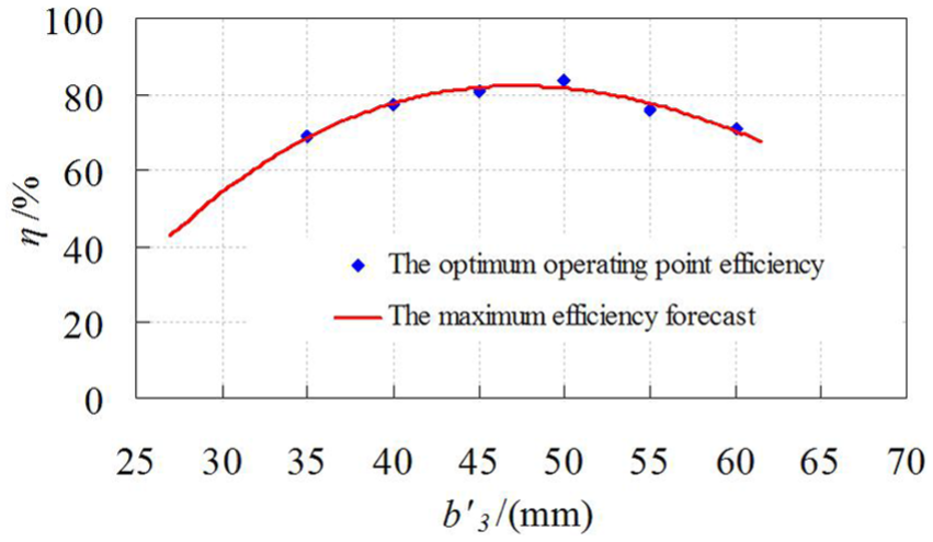
Pump maximum efficiency prediction.
The optimum operating point with different inlet widths in high-efficiency zone.

Test analysis
To verify the accuracy of the numerical results further, four submersible pumps with different diffuser inlet widths of 35, 45, 55, and 60 mm were manufactured and tested, respectively. Various indicators were tested on test bench of Lanzhou University of Technology. The pump flow rate was measured by a turbine flow meter; instrument accuracy was 0.2%. The pump outlet pressure was measured by a pressure transmitter; instrument accuracy was 0.1%.
The calculated results of pump performance were compared with the tested results in Figure 6. Table 5 provides the analog values and tested value data under four diffuser inlet width conditions.

Performance curve of a pump model: (a) b3 = 35 mm, (b) b3 = 45 mm, (c) b3 = 55 mm, and (d) b3 = 60 mm.
Analog and test values of single-stage heads with different inlet widths.

As shown in Figure 6, the numerical results of the submersible pump performance are consistent with the test results. Along with the increase in diffuser inlet width, the optimum operating point of the submersible pump offsets to the larger flow rate. This conclusion coincides with the theoretical analysis results.
Table 5 compares the numerical and test results, and the numerical results are higher. The main reasons are as follows: (1) the gap between the impeller and the diffuser was neglected, (2) the RNG k–ε turbulence model is an approximate treatment of practical problems under certain conditions, the discrepancy and the rounding error will also influence the calculation result, and (3) computing boundary conditions, meshing, and simplification of practical problems are also the causes of the error.
According to relative error formula, the relative error values of the pump head were calculated. The maximum value was 13.79%, the minimum value was 0.65%, and the average relative error was 7.35%. The error value was small, and the credibility of the simulation results was higher.
Conclusion
Along with an increase in diffuser inlet width, the angle between the diffuser characteristic curve and the horizontal axis has a decreasing trend. The optimum operating point of the submersible pump offsets to the larger flow rate.
The optimum value of the diffuser inlet width exists, that is, b3 = 50 mm, which is larger than the experience-based one. When designing the diffuser, the value of the inlet width can be slightly larger than the experience-based one.
When the diffuser inlet width was located at approximately 40–55 mm, the submersible pump efficiency was relatively higher (approximately 75.9%–83.7%), and flow rates were approximately 105–135 m3/h. The practical significance was supplied under a range of conditions by changing the inlet width of diffuser to expand the use and scope.
Footnotes
Academic Editor: Jianqiao Ye
Declaration of conflicting interests
The author(s) declared no potential conflicts of interest with respect to the research, authorship, and/or publication of this article.
Funding
The author(s) disclosed receipt of the following financial support for the research, authorship, and/or publication of this article: This project is supported by National Natural Science Foundation of China (grant no. 51179116) and Shanxi Provincial Natural Science Foundation of China (grant no. 201601D102045).